 Open Access Article
Creative Commons Attribution 3.0 Unported Licence
Impact of the crystalline phase of binary silicide on its lithiation and delithiation properties†
Yasuhiro
Domi
 ab,
Hiroyuki
Usui
 ab,
Takumi
Ando
bc and
Hiroki
Sakaguchi
 *ab
*ab
aDepartment of Chemistry and Biochemistry, Graduate School of Engineering, Tottori University, 4-101 Minami, Koyama-cho, Tottori 680-8552, Japan. E-mail: sakaguch@tottori-u.ac.jp
bCentre for Research on Green Sustainable Chemistry, Tottori University, 4-101 Minami, Koyama-cho, Tottori 680-8552, Japan
cDepartment of Engineering, Graduate School of Sustainability Science, Tottori University, 4-101 Minami, Koyama-cho, Tottori 680-8552, Japan
First published on 4th July 2022
Abstract
In this work, we investigate the impact of the crystalline phase of binary silicide on its lithiation and delithiation properties. Charge–discharge testing shows that the reversible capacity is not dependent on the amount of Si included in the silicide; the capacity was found to be independent of the composition of the silicide even in the case of a given transition metal making up the silicide. The results of this study confirm that there is no phase separation of the silicide during the charge–discharge reactions. A high reversible capacity could be obtained when the affinity of the transition metal for Li was large and the distance between the Li atoms and the nearest-neighbour atom in lithiated silicide was large.
Introduction
Rechargeable batteries are essential to the transition toward building a carbon-neutral society. In particular, lithium-ion batteries (LIBs) are widely utilized as power sources across a wide range of applications.1,2 LIBs are a mature and established technology, and their demand will not decrease rapidly even if new rechargeable batteries are developed in the future. However, although the material composition of current LIBs is excellent, there is still considerable potential for material development to improve the energy density of LIBs.Silicon (Si) is an important active material for the negative electrodes of future LIBs because it has a high theoretical capacity of 3580 mA h g−1; this value is considerably higher than that of graphite (372 mA h g−1), which is currently used for this purpose. However, Si electrodes exhibit an inferior cycle life, which is primarily caused by a considerable change in volume during charge (lithiation) and discharge (delithiation).3–5 To improve this poor cycle life, various approaches have been investigated. These include preparation of nano Si materials that alleviate the stress due to volumetric change;4,6–8 covering Si with carbon materials to decrease the electrical resistivity;6,9–11 doping of Si with impurities (such as phosphorous and arsenic) to change its properties, including phase transition, morphology, crystallinity, electronic conductivity and Li+ diffusion;5,12–16 synthesizing composites composed of binary or ternary silicide and pure Si to counter some of the drawbacks of Si;17–27 and pre-lithiation of Si with the aim of increasing the initial Coulombic efficiency of the electrode.28–32
With the objective of overcoming the drawbacks of Si for applications as the negative electrode in LIBs, we synthesize pure binary silicides and investigate their charge and discharge properties as well as their reaction.33,34 We find that some silicide electrodes exhibit a high discharge capacity and superior cyclability in an ionic liquid electrolyte. The discharge capacity correlates with the charge density of transition metals; when the affinity of the transition metal with Li is high, the capacity is high. Additionally, a surface film derived from an ionic liquid electrolyte is homogeneous and thin, which leads to uniform lithiation of Si. The superior cyclability results from the surface film properties. However, the impact of the different crystalline phases of the binary silicide on its lithiation and delithiation properties remains unclear. Herein, we aim to clarify the relationship between the crystalline phase of silicide (MSix, M: metal) and its charge–discharge properties. We focus on the use of Ni and Fe as M because NiSi2 and FeSi2 have a relatively high reversible capacity due to the high affinity of M with Li,33 and these silicides have several different crystalline phases. We find promising Si-based active materials for negative electrodes in LIBs with high gravimetric and/or volumetric energy densities in this work.
Experimental
Synthesis of silicides
We synthesized MSix (M = Ni or Fe, x = 2, 1, 1/2 or 1/3) powders via a mechanical alloying (MA) method using optimized conditions, as shown in Table S1 (ESI†). For the MA process, we used a high-energy planetary ball mill (P-6, Fritsch). The elemental Si (99.9%) and iron (99.9%) powders were purchased from FUJIFILM Wako Pure Chemical Corporation, Ltd. Additionally, we obtained nickel (99.9%) from Nilaco Corporation. We placed a mixture of Si and M in a ZrO2 container along with the ZrO2 balls; the weight ratio of the balls and the mixture was approximately 15![[thin space (1/6-em)]](https://www.rsc.org/images/entities/char_2009.gif) :
:![[thin space (1/6-em)]](https://www.rsc.org/images/entities/char_2009.gif) 1. The container was then filled with dry Ar gas. For treatment times of longer than 10 h, we opened the container in an Ar-filled glovebox and stirred the mixture using a spatula every 10 h.
1. The container was then filled with dry Ar gas. For treatment times of longer than 10 h, we opened the container in an Ar-filled glovebox and stirred the mixture using a spatula every 10 h.
Characterization
We confirmed the crystal structure of the synthesized powders using X-ray diffraction (XRD, Ultima IV, Rigaku), and we identified the obtained XRD patterns via comparison with those available on the Inorganic Crystal Structure Database (ICSD). Additionally, we confirmed the absence of elemental Si in the synthesized powders using Raman spectroscopy (NanofinderFLEX; Tokyo Instruments, Inc.); the absence of elemental Si is important as the properties of each silicide cannot be accurately evaluated if pure Si is present. We obtained the Raman spectra with the 532 nm line (16.5 mW) of a Nd:YAG laser through a 50× objective lens. The average particle size of the synthesized powder was estimated using a particle size distribution analyser (SALD-2300, Shimadzu). The powder (ca. 0.1 g) was dispersed ultrasonically in 0.5 wt% sodium hexametaphosphate aqueous solution (approximately 10 ml). We analysed the particle size distribution by diluting the prepared suspension.Electrode preparation by using a gas deposition method
We used the gas deposition (GD) method to prepare the silicide electrodes. Using this method, it is possible to investigate the original charge–discharge properties of active materials because the GD method requires no conductive agent or binder.35,36 We used 99.9999% helium gas as a carrier gas. The conditions used in the GD process are reported in ref. 12 and 37. The weight of the deposited MSix powder on a Cu current collector (thickness: 20 mm, Hohsen Corp.) was approximately 30 μg.Coin cell assembly and charge–discharge testing
We assembled a 2032-type coin cell, which was composed of the electrode prepared via the GD method as the working electrode, a Li metal foil (thickness: 1 mm, 99.9%, Rare Metallic Co., Ltd) as the counter electrode, 1 mol dm−3 (M) lithium bis (fluorosulfonyl)amide (LiFSA) in N-methyl-N-propylpyrrolidinium bis (fluorosulfonyl)amide (Py13-FSA) as the electrolyte and a glass fibre filter (Whatman GF/A) as the separator in an Ar-filled glovebox (Miwa MFG, DBO-2.5LNKP-TS) with an oxygen content of less than 1 ppm and a dew point below −90 °C. We chose 1 M LiFSA/Py13-FSA as the electrolyte because Si-based electrodes exhibited a superior cycling performance in 1 M LiFSA/Py13-FSA.15,24,27,33 LiFSA and Py13-FSA were purchased from Kishida Chemical Co., Ltd and Kanto Chemical Co., Inc., respectively.A galvanostatic lithiation–delithiation testing of the MSix electrode was conducted using a battery charge/discharge system (HJ-1001SD8 and HJ-1001SM8A, Hokuto Denco Co., Ltd) at a temperature of 30 °C. The testing was performed in the potential range from 0.005 to 2.000 V versus Li+/Li at a current density of 50 mA g−1. In the first cycle, the testing was carried out from an open circuit potential (OCP).
First principles calculation
A first principles calculation based on density functional theory (DFT) was carried out to investigate the charge density distribution in Li0.25MSix (M = Ni or Fe, x = 2, 1, 1/2 or 1/3), with the exception of Li0.25NiSi1/3, using the Advance/PHASE software package (Advance Soft Corp.). Li1/3NiSi1/3 was added to ensure that the number of Li atoms in each lattice was the same. The projector augmented wave (PAW) method was adopted, and the generalized gradient approximation (GGA) was employed as the term exchange correlation. Values of 112.5 and 12.5 Hartree were applied as the cutoff values for the charge densities and the wave functions, respectively.Results and discussion
Synthesis of NiSix and FeSix with different crystalline phases
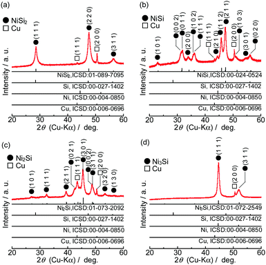
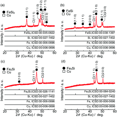
Fig. 1 shows XRD patterns of the powders synthesized from elemental Ni and Si with different mixture ratios. All of the diffraction peaks were consistent with the ICSD patterns of NiSi2, NiSi, Ni2Si or Ni3Si, and no peaks that would indicate the presence of the raw materials (Si, Ni and Fe) were found. Similar results were obtained in the case of FeSix (Fig. 2). The crystallite size of synthesized powders is summarized in Table S2 (ESI†).Fig. 3 shows the Raman spectra of the prepared samples. Raman bands assigned to crystalline Si (c-Si) and amorphous Si (a-Si) appear in the obtained patterns.38,39 NiSix and FeSix exhibited no Raman bands, and it can therefore be concluded that the synthesized powders contained neither c-Si nor a-Si. These results demonstrate that the crystalline NiSix and FeSix phases were successfully formed via MA. The physical properties of each phase are summarized in Table S3 (ESI†),40 and Fig. S1 and S2 (ESI†) show the crystal structure of NiSix and FeSix (x = 2, 1, 1/2 or 1/3) phases, respectively. Fig. 4 shows particle size distribution of NiSi2 and FeSi2. We can confirm that the average particle sizes of synthesized samples are almost the same. Hence, we can discuss the charge and discharge properties only by the difference in the crystalline phase.
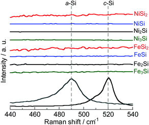 | ||
| Fig. 3 Raman spectra of NiSix and FeSix (x = 2, 1, 1/2 and 1/3) powders. For comparison, the spectra of c-Si and a-Si are also shown. | ||
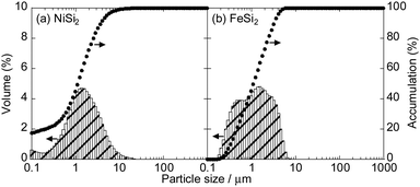 | ||
| Fig. 4 Particle size distribution of (a) NiSi2 and (b) FeSi2 particles in 0.5 wt% sodium hexametaphosphate aqueous solution. | ||
Lithiation and delithiation properties of the NiSix and FeSix electrodes
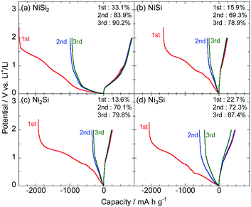
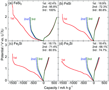
Fig. 5 and 6 show the initial charge–discharge curves of the NiSix and FeSix (x = 2, 1, 1/2 or 1/3) electrodes in 1 M LiFSA/Py13-FSA, respectively. Herein, the specific capacity (mA h g−1) in the horizontal axis indicates the weight of active materials (silicides). All the electrodes exhibited a plateau in the potential between 1.5 and 1.0 V on the initial charge curve, which result from the reductive decomposition of the electrolyte that forms a surface film. Reductive decomposition of FSA anion on Si electrodes occurs at approximately 1.4 V vs. Li+/Li.41 The initial Coulombic efficiency was found to be low due to decomposition of large quantities of the electrolyte. The efficiency improved during the second and third cycles due to the suppression of electrolyte decomposition.The initial Coulombic efficiencies of NiSi2 and FeSi2 were the highest between the NiSix and FeSix electrodes, respectively. It is considered that surface films with low electron conductivity formed on NiSi2 and FeSi2 electrodes. Silicate has been detected as a surface film component on Si-based electrodes even though the electrolyte has no Si component.42 That is, a part of the active material can be a surface film, and hence, the composition of silicides should affect the reductive decomposition products of the electrolyte.
We could confirm potential slopes of less than 1.0 V on charge and discharge curves irrespective of the cycle number. It is well known that the alloying and dealloying reactions of Si electrodes with Li occur at approximately 0.1 and 0.4 V on charge and discharge curves, respectively.43 Consequently, it can be concluded that no phase separation of silicide (e.g., FeSi2 + yLi+ + ye− → LiySi2 + Fe and/or FeSi2 + yLi+ + ye− → LiySi + FeSi) occurs and the silicide itself reacts with Li.34
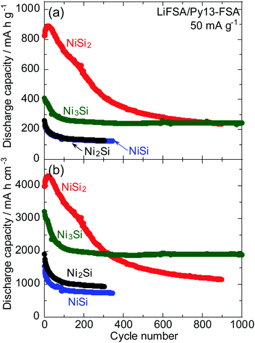
Fig. 7a shows the dependence of the gravimetric discharge capacity of NiSix (x = 2, 1, 1/2 or 1/3) electrodes on the cycle number in 1 M LiFSA/Py13-FSA. The corresponding capacity retention is also shown in Fig. S3 (ESI†). The initial capacity was found to be independent on the value of x; the NiSi2 electrode was found to exhibit the highest reversible capacity of over 800 mA h g−1, and the Ni3Si electrode was found to have the middle capacity of approximately 400 mA h g−1. Additionally, the NiSi and Ni2Si electrodes were found to have a lower initial capacity of 200 mA h g−1. The fact that NiSi2 has the highest initial discharge capacity among the four NiSix indicates that NiSi2 alloys and dealloys with more Li. Hence, the change in NiSi2 volume is larger compared to those of the other nickel silicides and the electrode disintegration should occur, which results in capacity fading.
High volumetric capacity is also essential for the fabrication of small batteries. The densities of NiSi2, NiSi, Ni2Si and Ni3Si are 4.83, 5.96, 7.37 and 7.84 g cm−3, respectively; the density of NiSix increases with decreasing values of x. Fig. 7b shows the dependence of the volumetric discharge capacity of the NiSix electrodes on the cycle number. It is generally the case that the gravimetric capacity is represented per mass of the unlithiated active material, whereas the volumetric capacity is frequently expressed per volume of the fully lithiated material.44 However, the precise Li amount alloyed with NiSix is unclear;33 thus, the capacity per volume of Li-free silicide is reported here. That is, the volumetric capacity is expressed as the product of the gravimetric capacity and the density. At the 300th cycle, the volumetric capacity of the Ni3Si electrode exceeded that of the NiSi2 electrode; the Ni3Si electrode thus exhibited a superior cycle stability and should be a promising negative electrode for LIBs with high volumetric energy density.
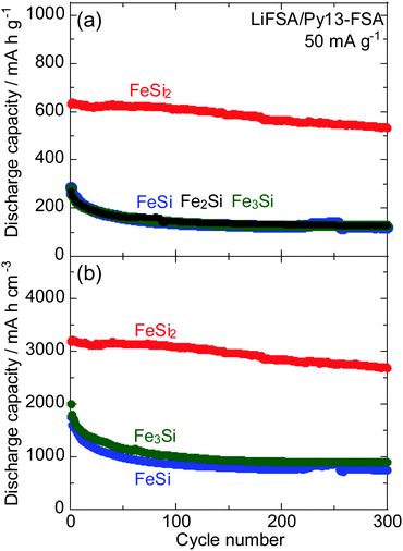
Fig. 8 shows cycling performance of the FeSix electrodes in 1 M LiFSA/Py13-FSA. The corresponding capacity retention was also shown in Fig. S4 (ESI†). The FeSi2 electrode exhibited the highest gravimetric and volumetric reversible capacities among the four FeSix electrodes. The gravimetric discharge capacities of the other electrodes (FeSi, Fe2Si and Fe3Si) were found to be similar. The Fe3Si electrode also showed slightly higher volumetric capacity compared to the FeSi electrode because the former has larger density. It should be noted that volumetric discharge capacity of the Fe2Si electrode cannot be calculated because the density of Fe2Si is unclear.
It has been previously reported that the silicide phase does not separate into Si and metal and/or Si-poor silicide phases during charge–discharge processes; the reversible capacity is not obtained by lithiation and delithiation of the Si phase.34Fig. 7 and 8 demonstrated that the discharge capacity is not correlated with the amount of Si included in the silicide. This result also reaffirms that no phase separation of silicide occurs during charge–discharge reactions.
Charge density distribution and distance between Li and nearest-neighbour atom
Here, we investigated the cause of the differing discharge capacity in the crystalline phase based on computational chemistry, despite the silicide being composed of the same metal and Si. Herein, we calculated charge density of each element in lithiated NiSix (x = 2, 1, 1/2 or 1/3, Table 1). Fig. S5 (ESI†) also shows the crystal structure of each lithiated NiSix. We could not perform the corresponding calculation for lithiated FeSix since the crystal structure of lithiated FeSix was optimized only for lithiated FeSi2. It has previously reported that the reversible capacity increases when the affinity of the metal composed making up the silicide for Li is large.33 Here, the affinity is defined as the difference in charge density between Li and the metal.| Li | Si | Ni | Initial discharge capacity/mA h g−1 | |
|---|---|---|---|---|
| Li0.25NiSi2 | +0.78 | +0.40 | −1.00 | 824 |
| Li0.25NiSi | +0.52 | +0.35 | −0.48 | 260 |
| Li0.25Ni2Si | +0.61 | +0.55 | −0.35 | 261 |
| LiNi3Si | +0.63 | +0.52 | −0.39 | 410 |
In Table 1, Li0.25NiSi2 is seen to have the largest affinity of Ni for Li and the highest initial discharge capacity. By contrast, Li0.25NiSi, Li0.25Ni2Si and LiNi3Si are seen to have very similar affinities, whereas the Li0.25NiSi and Li0.25Ni2Si are seen to have the lowest initial capacity and the LiNi3Si exhibits the middle capacity; this difference in capacity cannot be explained only by the affinity between Ni and Li. Hence, we investigate the distance between the Li atoms and its nearest–neighbour atoms in the lithiated NiSix (Table 2 and Fig. S6, ESI†). The Li0.25NiSi2 was found to have the largest distance, Li0.25Ni2Si and LiNi3Si showed middle distances, and the distance of Li0.25NiSi was the shortest. When the distance is large, the capacity tends to be larger; under this condition, the Li atoms should be relatively free to move in the silicide and diffuse evenly. Focusing again on the affinity of Li0.25Ni2Si and LiNi3Si, the latter exhibited a higher value. Consequently, the difference in the capacity of silicide can be understood by considering both the affinity of metal that makes up the silicide for Li and the distance between Li and nearest-neighbour atom in lithiated silicide.
| Distance/nm | Initial discharge capacity/mA h g−1 | |
|---|---|---|
| Li0.25NiSi2 | 0.234 | 824 |
| Li0.25NiSi | 0.134 | 260 |
| Li0.25Ni2Si | 0.172 | 261 |
| LiNi3Si | 0.175 | 410 |
Conclusions
In the present study, we synthesized various pure binary silicides in which the crystalline phase differed using the same metal, and investigated the impact of the crystalline phase of silicide on its lithiation and delithiation properties. The NiSi2 electrode exhibited the highest reversible capacity of over 800 mA h g−1 and the Ni3Si electrode was found to have the middle capacity. NiSi and Ni2Si electrodes were also found to have a lower initial capacity. The Ni3Si electrode should be a promising negative electrode for LIBs with high volumetric energy density. By contrast, the FeSi2 electrode exhibited the highest discharge capacity among the four FeSix electrodes, and the capacities of other FeSi, Fe2Si and Fe3Si electrodes were found to be very similar. Therefore, it was concluded that the reversible capacity was unrelated to the amount of Si included in the silicide; the capacity differed depending on x in MSix even if M was the same. The results confirmed that no phase separation of the silicide occurred during the charge–discharge reactions. A high discharge capacity was generally found when the affinity of M which made up the silicide for Li was large and the distance between Li and the nearest-neighbour atom in lithiated MSix was large.Author contributions
The manuscript was written through the contributions of all authors.Conflicts of interest
There are no conflicts to declare.Acknowledgements
This study was partially supported by the Japan Society for the Promotion of Science (JSPS) KAKENHI (Grant No. JP1905649, JP19H02817 and JP20H00399).Notes and references
- M. S. Whittingham, Chem. Rev., 2004, 104, 4271–4301 CrossRef CAS PubMed.
- M. Armand and J.-M. Tarascon, Nature, 2008, 451, 652–657 CrossRef CAS PubMed.
- M. N. Orrovac and L. J. Krause, J. Electrochem. Soc., 2007, 154, A103–A108 CrossRef.
- X. H. Liu, L. Zhong, S. Huang, S. X. Mao, T. Zhu and J. Y. Huang, ACS Nano, 2012, 6, 1522–1531 CrossRef CAS PubMed.
- Y. Domi, H. Usui, K. Yamaguchi, S. Yodoya and H. Sakaguchi, ACS Appl. Mater. Interfaces, 2019, 11, 2950–2960 CrossRef CAS PubMed.
- U. Kasavajjula, C. Wang and A. J. Appleby, J. Power Sources, 2007, 163, 1003–1039 CrossRef CAS.
- B. Hertzberg, A. Alexeev and G. Yushin, J. Am. Chem. Soc., 2010, 132, 8548–8549 CrossRef CAS PubMed.
- B. Liang, Y. Liu and Y. Xu, J. Power Sources, 2014, 267, 469–490 CrossRef CAS.
- L.-F. Cui, R. Ruffo, C. K. Chan, H. Peng and Y. Cui, Nano Lett., 2009, 9, 491–495 CrossRef CAS PubMed.
- L.-F. Cui, Y. Yang, C.-M. Hsu and Y. Cui, Nano Lett., 2009, 9, 3370–3374 CrossRef CAS PubMed.
- N. Liu, H. Wu, M. T. McDowell, Y. Yao, C. Wang and Y. Cui, Nano Lett., 2012, 12, 3315–3321 CrossRef CAS PubMed.
- Y. Domi, H. Usui, M. Shimizu, Y. Kakimoto and H. Sakaguchi, ACS Appl. Mater. Interfaces, 2016, 8, 7125–7132 CrossRef CAS PubMed.
- S. Huang, L.-Z. Cheong, D. Wang and C. Shen, ACS Appl. Mater. Interfaces, 2017, 9, 23672–23678 CrossRef CAS PubMed.
- W.-C. Chang, K.-W. Tseng and H.-Y. Yuan, Nano Lett., 2017, 17, 1240–1247 CrossRef CAS PubMed.
- S. Yodoya, Y. Domi, H. Usui and H. Sakaguchi, ChemistrySelect, 2019, 4, 1375–1378 CrossRef CAS.
- D. Lau, C. A. Hall, S. Lim, J. A. Yuwano, P. A. Burr, N. Song and A. Lennon, ACS Appl. Energy Mater., 2020, 3, 1730–1741 CrossRef CAS.
- H. Sakaguchi, T. Iida, M. Itoh, N. Shibamura and T. Hirono, IOP Conf. Ser.: Mater. Sci. Eng., 2009, 1, 012030 Search PubMed.
- H. Usui, K. Maebara, K. Nakai and H. Sakaguchi, Int. J. Electrochem. Sci., 2011, 6, 2246–2254 CAS.
- H. Usui, M. Nomura, H. Nishino, M. Kusatsu, T. Murota and H. Sakaguchi, Mater. Lett., 2014, 130, 61–64 CrossRef CAS.
- H. Usui, K. Nouno, Y. Takemoto, K. Nakada, A. Ishii and H. Sakaguchi, J. Power Sources, 2014, 268, 848–852 CrossRef CAS.
- Y. Domi, H. Usui, Y. Takemoto, K. Yamaguchi and H. Sakaguchi, J. Phys. Chem. C, 2016, 120, 16333–16339 CrossRef CAS.
- Y. Domi, H. Usui, Y. Takemoto, K. Yamaguchi and H. Sakaguchi, Chem. Lett., 2016, 45, 1198–1200 CrossRef CAS.
- Y. Domi, H. Usui, E. Nakabayashi, Y. Kimura and H. Sakaguchi, ACS Appl. Energy Mater., 2020, 3, 7438–7444 CrossRef CAS.
- Y. Domi, H. Usui, Y. Shindo, S. Yodoya, H. Sato, K. Nishikawa and H. Sakaguchi, Electrochemistry, 2020, 88, 548–554 CrossRef CAS.
- Y. Kimura, Y. Domi, H. Usui and H. Sakaguchi, Electrochemistry, 2020, 88, 330–332 CrossRef CAS.
- Y. Kimura, Y. Domi, H. Usui and H. Sakaguchi, ACS Omega, 2021, 6, 8862–8869 CrossRef CAS PubMed.
- Y. Domi, H. Usui, K. Nishikawa and H. Sakaguchi, ACS Appl. Nano Mater., 2021, 4, 8473–8481 CrossRef CAS.
- N. Liu, L. Hu, M. T. McDowell, A. Jackson and Y. Cui, ACS Nano Lett., 2011, 5, 6487–6493 CrossRef CAS PubMed.
- T. Okubo, M. Saito, C. Yodoya, A. Kamei, M. Horita, T. Takenaka, T. Okumura, A. Tasaka and M. Inaba, Solid State Ionics, 2014, 262, 39–42 CrossRef CAS.
- Y. Domi, H. Usui, D. Iwanari and H. Sakaguchi, J. Electrochem. Soc., 2017, 164, A1651–A1654 CrossRef CAS.
- M. Saito, K. Kato, S. Ishii, K. Yoshii, M. Shikano, H. Sakaebe, H. Kiuchi, T. Fukunaga and E. Matsubara, J. Electrochem. Soc., 2019, 166, A5174–A5183 CrossRef CAS.
- Y. Domi, H. Usui, N. Ieuji, K. Nishikawa and H. Sakaguchi, ACS Appl. Mater. Interfaces, 2021, 13, 3816–3824 CrossRef CAS PubMed.
- Y. Domi, H. Usui, R. Takaishi and H. Sakaguchi, ChemElectroChem, 2019, 6, 581–589 CrossRef CAS.
- Y. Domi, H. Usui, K. Sugimoto, K. Gotoh, K. Nishikawa and H. Sakaguchi, ACS Omega, 2020, 5, 22631–22636 CrossRef CAS PubMed.
- H. Sakaguchi, T. Toda, Y. Nagao and T. Esaka, Electrochem. Solid-State Lett., 2007, 10, J146–J149 CrossRef CAS.
- H. Usui, Y. Kiri and H. Sakaguchi, Thin Solid Films, 2012, 520, 7006–7010 CrossRef CAS.
- Y. Domi, H. Usui, M. Shimizu, K. Miwa and H. Sakaguchi, Int. J. Electrochem. Sci., 2015, 10, 9678–9686 CAS.
- M. Shimizu, H. Usui, T. Suzumura and H. Sakaguchi, J. Phys. Chem. C, 2015, 119, 2975–2982 CrossRef CAS.
- K. Yamaguchi, Y. Domi, H. Usui and H. Sakaguchi, ChemElectroChem, 2017, 4, 3257–3263 CrossRef CAS.
- C. Tang, F. Wen, H. Chen, J. Liu, G. Tao, N. Xu and J. Xue, J. Alloys Compd., 2019, 778, 972–981 CrossRef CAS.
- K. Yamaguchi, Y. Domi, H. Usui, M. Shimizu, K. Matsumoto, T. Nokami, T. Itoh and H. Sakaguchi, J. Power Sources, 2017, 338, 103–107 CrossRef CAS.
- Y. Kimura, Y. Domi, H. Usui and H. Sakaguchi, J. Electrochem. Soc., 2022, 169, 010537 CrossRef.
- V. L. Chevrier, J. W. Zwanziger and J. R. Dahn, J. Alloys Compd., 2010, 496, 25–36 CrossRef CAS.
- N. Nitta and G. Yushin, Part. Part. Syst. Charact., 2014, 31, 317–336 CrossRef CAS.
Footnote |
| † Electronic supplementary information (ESI) available. See DOI: https://doi.org/10.1039/d2ma00171c |
| This journal is © The Royal Society of Chemistry 2022 |

