 Open Access Article
Creative Commons Attribution 3.0 Unported Licence
Photocatalytic conversion of arylboronic acids to phenols by a new 2D donor–acceptor covalent organic framework†
Bingcai
Luo‡
,
Yubao
Zhang‡
,
Ying
Chen
and
Jianqiang
Huo
 *
*
College of Chemistry and Chemical Engineering, Key Laboratory of Eco-functional Polymer Materials of the Ministry of Education, Key Laboratory of Eco-environmental Polymer Materials of Gansu Province, Northwest Normal University, Lanzhou 730070, P. R. China. E-mail: huojianqiang@hotmail.com
First published on 11th April 2022
Abstract
Covalent organic frameworks (COFs) are a kind of promising crystalline material for photocatalytic organic conversion. The introduction of electron donor–acceptor (D–A) units into its structure can reasonably adjust the photoelectric properties and energy bandwidth of COFs. In this research, we designed and synthesized a two-dimensional (2D) D–A type COF (BTT-BTDDA-COF) based on alternating connections of benzotrithiophene (BTT) and 4,4’-(2,1,3-benzothiadiazole-4,7-diyl)dianiline (BTDDA) units, with a wide visible light absorption range and good photoelectric response characteristics. In the photocatalytic conversion of arylboronic acid to phenol, BTT-BTDDA-COF exhibits high catalytic activity, wide substrate applicability and good recoverability. The high-efficiency photocatalytic activity of BTT-BTDDA-COF is reasonably attributed to the electron push–pull effect between the donor and acceptor units, which significantly improves the transfer and separation of carriers, which leads to the expansion of the visible light absorption range. The above results show the practicability of COFs material design and provide a new idea for the application of the new D–A COF catalyst in photocatalytic organic conversion.
1. Introduction
The increasingly serious global energy crisis and ecological environmental pollution have become the greatest threat to human society today.1 Solar energy as one of the most abundant renewable energies provides a new way to solve these problems.2 The development of photocatalytic materials with the advantages of low energy consumption and being pollution-free is the most critical key factor.3 Researchers have conducted many explorations on inorganic semiconductor materials with clear energy band structures such as TiO2,4 ZnO,5 and MoS2,6 and found that they have good absorption of light in the ultraviolet region. At the same time, in order to improve the photocatalytic performance and expand the absorption range of visible light, the research of organic photocatalysts such as organic dyes,7g-C3N4,8 MOFs9 and COFs10–16 has gradually attracted people's attention. In contrast, COFs are often used as a photocatalytic material because of their good chemical stability and adjustable chemical structure.17–24With extended π-conjugated frameworks, excellent stability and adjustable chemical structures, COFs have shown great potential for broad applications in many prospects, such as phototransistors, optoelectronic devices and photocatalytic reactions.25–32 Recently, reactions like redox, CH functionalization and E/Z isomerization have proved that covalent organic frameworks have great appeal in visible light-driven organic transformations.33–37 They provide a simple and environmentally friendly method for the synthesis of important chemicals. At present, a variety of COFs catalysts have been developed by researchers and are still being explored. Consequently, it is necessary to design and synthesize COFs catalysts with high photocatalytic activity. Generally, a high-efficiency photocatalyst should have a wide light absorption range, an appropriate band gap, and effective charge transport capabilities. A feasible method is to design a COF with alternately connected electron donor–acceptor units in the framework through a reasonable molecular design strategy.
The design and construction of a COF with a donor–acceptor (D–A) structure has been proved to be an effective method to reduce the band gap and accelerate the intramolecular charge transfer.38–42 However, the current research on COFs reports low catalytic efficiency and limited selection.43–48 Through a literature review, we found that the bottom-up design method provides great possibilities for the synthesis of new high-performance COF catalysts.23,49–58 As is well known, the 4,4′-(2,1,3-benzothiadiazole-4,7-diyl)dianiline (BTDDA) unit is currently one of the most effective electron acceptors. It can adjust the band gap and improve the charge separation and transfer properties of polymers. In addition, the pairing of BTDDA and electron-rich units can lead to significant delocalization of charges within the conjugated framework molecule, and the resulting polymer exhibits a narrower band gap and enhanced light absorption in the near-infrared region. Our previous study59 has shown that the benzotrithiophene (BTT) unit can be designed as an efficient COF photocatalyst and has good photosensitivity.
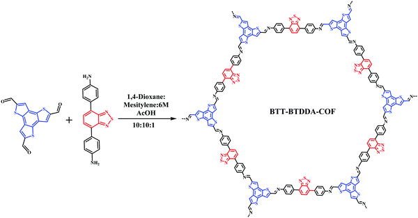
As a proof of inspiration, a new COF (BTT-BTDDA-COF) was successfully synthesized from electron donor unit benzotrithiophene (BTT) and electron acceptor unit 4,4′-(2,1,3-benzothiadiazole-4,7-diyl)dianiline (BTDDA) through the bottom-up Schiff base reaction. The new COF constitutes a D–A type structure. Meanwhile, the structural composition and photocatalytic organic conversion performance have been studied. As expected, BTT-BTDDA-COF provides a suitable energy band structure, strong visible light absorption capacity and fast electron migration rate, making it a highly active photocatalyst. As a matter of course it is applied in the photocatalytic conversion of aryl phenyl boronic acid to phenol.10,58,60–66 It exhibits high-efficiency catalytic performance and good recyclability. This work emphasizes the importance of constructing a well-defined D–A structure for the effective design of COF photocatalysts, and provides an effective strategy for the further design and synthesis of more efficient COF photocatalysts.
2. Experimental section
2.1 Materials and methods
All other reagents and solvents are analytically pure and can be used directly without further purification. X-ray photoelectron spectroscopy measurement was performed using an instrument (ThermoFisher Scientific, ESCALAB250Xi, USA). A CH Instruments 660E electrochemical workstation was used to test the photoelectric performance of the samples. 1H NMR and 13C NMR spectra were recorded with an Agilent 600 MHz spectrometer. FT-IR spectra were recorded from 400 to 4000 cm−1 by using KBr pellets on a DIGILAB FTS-3000 spectrometer. Powder X-ray diffraction (PXRD) patterns were taken on a D/max 2200PC diffractometer at room temperature. Morphology analysis was performed using an ULTRA Plus scanning electron microscope (SEM). Thermogravimetric analysis (TGA) was performed on a NETZSCH Instruments thermal analyzer (STA449C) from 25 to 800 °C at a heating rate of 10 °C min−1 under an N2 atmosphere. N2 adsorption–desorption isotherms were measured on an Autosorb iQ Station (QuantaChrome Instruments V 5.0) at 77 K, and the Brunauer–Emmett–Teller (BET) method was utilized to calculate the specific surface areas and pore volume. The UV-vis absorption spectra were recorded on an Agilent 8453 UV-vis spectrophotometer.2.2 Synthesis of BTT-BTDDA-COF
The synthesis method of BTT-BTDDA-COF is shown in Scheme 1. BTT (66.1 mg, 0.2 mmol) and BTDDA (95.5 mg, 0.3 mmol) were placed in a heat-resistant glass bottle with 1,4-dioxane (3 mL), methylene (3 mL) and 6 M AcOH (0.3 mL), respectively. After ultrasonic dispersion for 5 min, the mixture was sealed in an N2 atmosphere and heated at 120 °C for 3 days. After cooling to room temperature, the products were separated by centrifugation, washed with DMF, methanol and ethanol several times successively, and then Soxhlet extracted with THF for 24 h. Finally, the solid obtained was dried at 100 °C under vacuum for 12 h to obtain the red BTT-BTDDA-COF.3. Results and discussion
3.1 Fourier transform infrared spectroscopy characterization
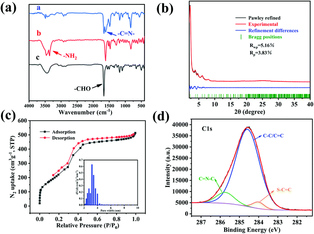
Through the FT-IR spectrum (Fig. 1(a)), we can find that a new imine bond (–C![[double bond, length as m-dash]](https://www.rsc.org/images/entities/char_e001.gif) N–) stretching vibration peak appears at 1608 cm−1, The amino group (–NH2) at 3364 cm−1 and the stretching vibration peak of the aldehyde group (–CHO) of 1665 cm−1 have basically disappeared, indicating that the two monomers have formed BTT-BTDDA-COF through the condensation reaction of the aldehyde and amine.
N–) stretching vibration peak appears at 1608 cm−1, The amino group (–NH2) at 3364 cm−1 and the stretching vibration peak of the aldehyde group (–CHO) of 1665 cm−1 have basically disappeared, indicating that the two monomers have formed BTT-BTDDA-COF through the condensation reaction of the aldehyde and amine.
3.2 Powder X-ray diffraction (PXRD) analysis
The structure of BTT-BTDDA-COF is simulated by Materials Studio software (Fig. 2) and Pawley refinement of PXRD (Fig. 1(b)). As shown in Fig. S2 (ESI†), BTT-BTDDA-COF has a strong diffraction peak at 2.32°, and four different diffraction peaks at 4.02°, 4.64°, 6.12° and 8.02°, which correspond to 100, 110, 200, 120 and 220 crystals, respectively. In addition, through Pawley refinement, a unit cell with space group P6 is obtained, the parameters are a = 44.277 Å, b = 44.277 Å, c = 4.3087 Å and α = 90°, β = 90°, γ = 120° (Table S1, ESI†), where Rwp = 5.16% and Rp = 3.83%. Compared with staggered AB stacking, the simulated PXRD pattern of overlapping AA stacking (Fig. S2, ESI†) is more consistent with the experimental data.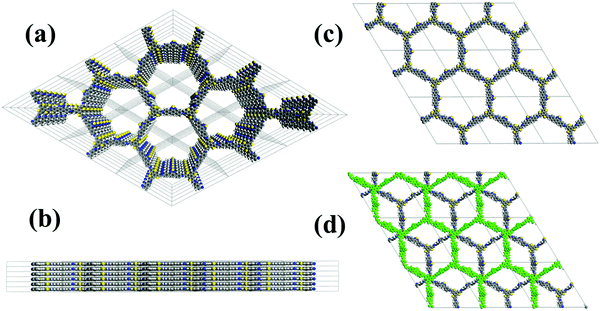 | ||
| Fig. 2 (a) Top and (b) side views of BTT-BTDDA-COF in the simulated AA eclipsed stacking model. (c) AA eclipsed stacking model for BTT-BTDDA-COF. (d) AB staggered stacking model for BTT-BTDDA-COF. | ||
3.3 Surface area measurement
The porosity and surface area of BTT-BTDDA-COF were measured by nitrogen adsorption–desorption experiments at 77 K. As shown in Fig. 1(c), the specific surface area of BTT-BTDDA-COF is 908.9257 m2 g−1. The pore size calculated by non-local density functional theory (NLDFT) is mainly distributed at 3.83 nm (Fig. 1(c)), which is basically consistent with the theoretical data (3.96 nm) obtained by the AA stacking model, which further shows that the BTT-BTDDA-COF with an excellent network structure was successfully synthesized.3.4 Surface morphology analysis
The surface morphology of BTT-BTDDA-COF was analyzed by SEM and TEM. Fig. S1(d–f, ESI†) is SEM images of BTT-BTDDA-COF at different magnifications. The SEM images show that BTT-BTDDA-COF has an irregular rod shape. EDS analysis (Fig. S1(g–k), ESI†) proves that C, N, and S elements are evenly distributed in the COF material, which is basically consistent with the results of XPS analysis. It can be seen from TEM (Fig. S1(a–c), ESI†) that BTT-BTDDA-COF has clear lattice fringes, which further confirms the high crystallinity of BTT-BTDDA-COF.3.5 X-Ray photoelectron spectroscopy (XPS) characterization
In order to prove the element types and valence states on the surface of BTT-BTDDA-COF we carried out XPS tests. As shown in Fig. S3 (ESI†), the main constituent elements of BTT-BTDDA-COF are C, N, and S.24,67–69 The C 1s peak at 284.58 eV is a carbon atom in the benzene ring, while the two C 1s peaks at 284.01 and 285.74 eV are derived from thiophene units and imine bonds, respectively (Fig. 1(d)). The XPS and FTIR results provide enough information about the structure of BTT-BTDDA-COF and prove that BTT-BTDDA-COF has been successfully synthesized.3.6 Stability analysis
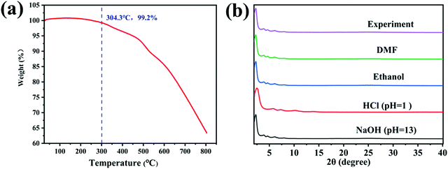
Considering the application range of the material, we explored the solvent stability and thermal stability of BTT-BTDDA-COF. Thermogravimetric analysis (Fig. 3(a)) shows that under a nitrogen atmosphere, BTT-BTDDA-COF can maintain a stable structure at a high temperature of 304.3 °C. In addition, the stability of the photocatalyst is also reflected in the material's good tolerance to solvents. Subsequently, at 25 °C, BTT-BTDDA-COF was soaked in different solutions for 3 days including N,N-dimethylformamide (DMF), ethanol, HCl (pH = 1) aqueous solution and NaOH aqueous solution (pH = 13). The solvent stability of BTT-BTDDA-COF was characterized by PXRD. It can be seen from the comparison of Fig. 3(b), that the position and intensity of each diffraction peak of BTT-BTDDA-COF before and after immersion in different solvents remain basically unchanged, which proves that it is stable in various solutions. Therefore, BTT-BTDDA-COF exhibits excellent thermal and chemical stability, which expands its application range in the field of photocatalysis.3.7 Photoelectric performance analysis
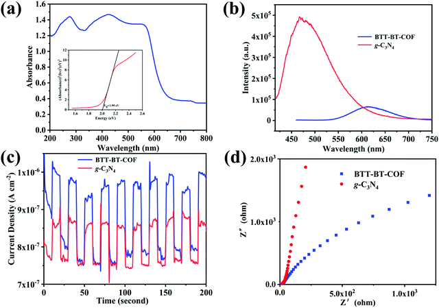
In order to study the optical properties of the material, the obtained BTT-BTDDA-COF was firstly analyzed by solid UV-vis diffuse reflectance spectroscopy (DRS). As shown in Fig. 4(a), BTT-BTDDA-COF shows a wide absorption peak of visible light, with the edge of the absorption band extending into the near infrared region. The wide absorption and narrow energy gap may be attributed to efficient intramolecular charge transfer from donor to recipient. In addition, BTT and BTDDA units also improve the conjugation degree in the system at the molecular level, which further promotes the carrier flow and reduces the band gap. The optical band gap was calculated as 1.99 eV by Tauc diagram. In order to further study the relative position of the valence band (VB) and conduction band (CB), XPS-VB analysis was carried out and the valence band value was 1.02 eV (Fig. S4(a), ESI†), and CB was calculated as −0.97 eV. It can be found by comparison (Fig. S4(b), ESI†) that BTT-BTDDA-COF is sufficient to reduce O2 to O2˙− (−0.33V vs. NHE). Obviously, THE EVB of BTT-BTDDA-COF fully meets the above criteria. In addition, the PL strength of BTT-BTDDA-COF is much weaker than that of g-C3N4 (Fig. 4(b)), which indicates that the recombination of BTT-BTDDA-COF photogenerated carriers is inhibited and has a high photoinduced electron hole pair separation efficiency.BTT-BTDDA-COF shows a fast photocurrent response under repeated cycles of visible illumination and multiple intermittent switching illuminations (Fig. 4(c)). Compared with g-C3N4, the BTT-BTDDA-COF photocurrent response is significantly enhanced, indicating that BTT-BTDDA-COF photogenerated charge can be separated more effectively. In addition, we also found that the photocurrent density of BTT-BTDDA-COF does not decay with the increase of the illumination time, which means that BTT-BTDDA-COF can provide a stable number of photogenerated electrons and holes during the illumination process. As can be seen from the EIS Nyquist diagram (Fig. 4(d)), compared with g-C3N4, BTT-BTDDA-COF has a smaller arc radius, indicating that it has a higher conductivity, thus enhancing the ability of electron transfer in the photocatalyst.
3.8 Study on the photocatalytic performance of BTT-BTDDA-COF
Triethylamine (as sacrifice electron donor) (0.3 mmol), catalyst BTT-BTDDA-COF (2 mg) and substrate benzenboric acid (0.1 mmol) were added into a transparent glass bottle filled with 3 mL acetonitrile. Under the irradiation of a 36 W blue LED lamp, phenol was separated and obtained after 26 h of reaction in an air atmosphere, with a yield of 93% (Table 1 entry 1). By comparison, we found that the reaction did not occur without the addition of photocatalyst (Table 1, entry 6), indicating that BTT-BTDDA-COF plays a decisive role in the catalytic reaction. We also tested the catalytic effect of BTT and BTDDA units on arylboronic acid. It can be seen from Table 1 entries 7 and 8 that BTT shows a low conversion rate (30%), while the BTDDA unit only has a 10% conversion rate, indicating that the structure of the D–A Type COF plays a key role in the catalytic reaction. A series of subsequent controlled experiments showed that the reaction was difficult to occur in the absence of either light, triethylamine, air, or oxygen (Table 1 entries 2–4). This suggests that light, triethylamine and oxygen are indispensable in the reaction. In a word, under blue light irradiation with BTT-BTDDA-COF as a photocatalyst, the phenylboronic acid has been successfully converted into phenol.| Entrya | Catalyst | Reaction condition variations | Yieldb (%) |
|---|---|---|---|
| a Reaction conditions: phenylboronic acid (0.1 mmol), photocatalyst (2 mg), Et3N (0.3 mmol), 3 mL CH3CN, air, 26 h, Blue LED (36 W). b Isolated yield. | |||
| 1 | BTT-BTDDA-COF | No change | 93 |
| 2 | BTT-BTDDA-COF | No light | <5 |
| 3 | BTT-BTDDA-COF | No O2 (N2) | Trace |
| 4 | BTT-BTDDA-COF | No Et3N | Trace |
| 5 | BTT-BTDDA-COF | benzoquinone | 20 |
| 6 | — | No change | Trace |
| 7 | BTT | No change | 30 |
| 8 | BTDDA | No change | 10 |
Subsequently, on the basis of catalytic oxidation of arylboronic acid, we further summarized the reaction range of BTT-BTDDA-COF photocatalytic arylboronic acid. As shown in Table 2, arylboronic acid can be well converted into the corresponding hydroxylation compounds regardless of whether the substitution groups are electron-deficient groups or electron-donating groups, and high yields can be obtained. It is noteworthy that the reaction rate of the electron-deficient group is faster than that of the electron-substituted arylboronic acid. This may be because superoxide anions can more easily access the vacant P orbitals of boron atoms in arylboronic acid containing electron-deficient substituents.1 In addition, 2-naphthol boric acid also showed good reactivity and yielded 2-naphthol with 82% yield (Table 2, entry 11).
3.9 Research on catalytic mechanism
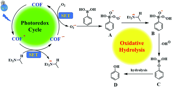
In the control experiment, we found that the photocatalytic reaction in a nitrogen atmosphere took place with only a small amount of transformation. Therefore, we hypothesize that O2 plays an important role in the reaction. Previous studies have reported that covalent organic frameworks can generate superoxide radical anions using solutions in visible light.60,70 To verify the presence of superoxide radicals in the reaction, benzoquinone was added as a free radical scavenger (Table 1, item 5). After 26 h of reaction, only 20% of arylboronic acid had been transformed. Therefore, based on previous work,10,61,62 we proposed the hydroxylation mechanism of arylboronic acid, as shown in Fig. 5. The excited state BTT-BTDDA-COF * produced under visible light irradiation, through the single electron transfer (SET) process to extract an electron from triethylamine, became BTT-BTDDA-COF˙− and Et3N˙+. Subsequently, BTT-BTDDA-COF˙− is oxidized by O2 to BTT-BTDDA-COF, which participates in the next catalytic cycle. At the same time, superoxide anion O2˙− is added to the vacant orbital of boron in arylboronic acid to form the intermediate peroxide radical A. The intermediate A then grabs an H atom from Et3N˙+ to form peroxide B. After that, the intermediate B loses an OH− ion and rearranges to form C. Finally, the final phenol product D was obtained by hydrolysis of intermediate C.3.10 Analysis of recyclability and catalytic performance
For catalysts, cycling stability is also one of the indicators of excellent performance. Therefore, the cycling performance of the catalyst was tested. After the reaction, the BTT-BTDDA-COF was centrifuged and washed with dichloromethane to ensure that no reaction substrate remained. The solid obtained was vacuum-dried at 100 °C and used for the next catalysis. To our delight, BTT-BTDDA-COF has a stable catalytic effect and can still maintain a good yield after 5 cycles (Fig. 6(a)), and XRD (Fig. 6(b)), FT-IR (Fig. S5, ESI†) and SEM (Fig. S6, ESI†) showed that the morphology, crystallinity and structure of the recovered BTT-BTDDA-COF catalyst did not change significantly. The BTT-BTDDA-COF catalyst has a stable spatial structure. In addition, we summarized the related organic polymers involved in the photocatalytic conversion of arylboronic acid to phenol in recent years (Table 3), and found that BTT-BTDDA-COF has obvious advantages.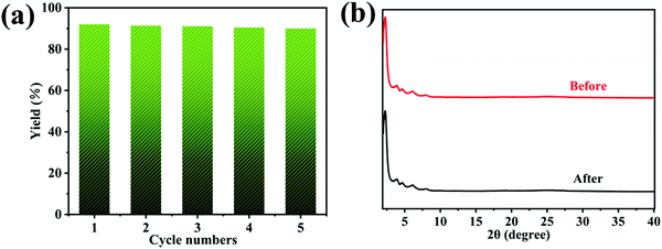 | ||
| Fig. 6 (a) Repeatability of BTT-BTDDA-COF in photocatalytic reactions; (b) XRD pattern before and after the reaction. | ||
4. Conclusions
In summary, we have successfully synthesized a novel D–A type covalent organic framework with high crystallinity, good stability and a wide range of visible light absorption. More importantly, BTT-BTDDA-COF shows high photocatalytic activity for the conversion of arylboronic acid to phenol, and can be reused many times without obvious loss of photocatalytic efficiency. This work paves the way for the design and construction of COF solid catalysts at the molecular level in the future, as well as its wider application in the field of organic transformation.Conflicts of interest
There are no conflicts to declare.References
- B. A. Simmons, R. Ray, H. Yang and K. P. Gallagher, Science, 2021, 371, 468–470 CrossRef CAS PubMed.
- Z. Song, J. Liu and H. Yang, Appl. Energy, 2021, 298, 117247 CrossRef CAS.
- S. Roy, J. Phys. Chem. C, 2020, 124, 28345–28358 CrossRef CAS.
- J. Li, Y. Lin, R. Chen, X. Zhu, D. Ye, Y. Yang, Y. Yu, D. Wang and Q. Liao, J. Energy Storage, 2021, 43, 103228 CrossRef.
- H. T. Kim, S.-Y. Lee, A. Slaoui, A. Dinia, H. J. Jeon and C. Park, Mater. Chem. Phys., 2021, 265, 124513 CrossRef CAS.
- Z. Guo, J. Wang, Y. Wang, J. Wang, J. Li, T. Mei, J. Qian and X. Wang, Chem. Eng. J., 2022, 427, 131008 CrossRef CAS.
- O. Bettucci, T. Skaltsas, M. Calamante, A. Dessì, M. Bartolini, A. Sinicropi, J. Filippi, G. Reginato, A. Mordini, P. Fornasiero and L. Zani, ACS Appl. Energy Mater., 2019, 2, 5600–5612 CrossRef CAS.
- H. Katsumata, T. Sakai, T. Suzuki and S. Kaneco, Ind. Eng. Chem. Res., 2014, 53, 8018–8025 CrossRef CAS.
- A. S. Morshedy, H. M. Abd El Salam, A. M. A. El Naggar and T. Zaki, Energy Fuels, 2020, 34, 11660–11669 CrossRef CAS.
- Z. J. Wang, R. Li, K. Landfester and K. A. I. Zhang, Polymer, 2017, 126, 291–295 CrossRef CAS.
- Y. Zhi, S. Ma, H. Xia, Y. Zhang, Z. Shi, Y. Mu and X. Liu, Appl. Catal., B, 2019, 244, 36–44 CrossRef CAS.
- S. Wang, Q. Sun, W. Chen, Y. Tang, B. Aguila, Y. Pan, A. Zheng, Z. Yang, L. Wojtas, S. Ma and F.-S. Xiao, Matter, 2020, 2, 416–427 CrossRef CAS.
- S. Yang, X. Li, Y. Qin, Y. Cheng, W. Fan, X. Lang, L. Zheng and Q. Cao, ACS Appl. Mater. Interfaces, 2021, 13, 29471–29481 CrossRef CAS PubMed.
- F. Su, S. C. Mathew, L. Mohlmann, M. Antonietti, X. Wang and S. Blechert, Angew. Chem., 2011, 50, 657–660 CrossRef CAS PubMed.
- J. L. Shi, R. Chen, H. Hao, C. Wang and X. Lang, Angew. Chem., 2020, 59, 9088–9093 CrossRef CAS PubMed.
- Z. J. Wang, S. Ghasimi, K. Landfester and K. A. I. Zhang, J. Mater. Chem. A, 2014, 2, 18720–18724 RSC.
- L. Niu, X. Zhao, F. Wu, H. Lv, Z. Tang, W. Liang, X. Wang and J. Giesy, Chem. Eng. J., 2021, 414, 128619 CrossRef CAS.
- G. B. Damas, C. F. N. Marchiori and C. M. Araujo, J. Phys. Chem. C, 2019, 123, 25531–25542 CrossRef CAS.
- A. M. Elewa, M. H. Elsayed, A. F. M. El-Mahdy, C.-L. Chang, L.-Y. Ting, W.-C. Lin, C.-Y. Lu and H.-H. Chou, Appl. Catal., B, 2021, 285, 119802 CrossRef CAS.
- K. Feng, H. Hao, F. Huang, X. Lang and C. Wang, Mater. Chem. Front., 2021, 5, 2255–2260 RSC.
- Q. Li, J. Wang, Y. Zhang, L. Ricardez-Sandoval, G. Bai and X. Lan, ACS Appl. Mater. Interfaces, 2021, 13, 39291–39303 CrossRef CAS PubMed.
- M. Tian, Y. Wang, X. Bu, Y. Wang and X. Yang, Catal. Sci. Technol., 2021, 11, 4272–4279 RSC.
- Z. Li, Y. Zhi, P. Shao, H. Xia, G. Li, X. Feng, X. Chen, Z. Shi and X. Liu, Appl. Catal., B, 2019, 245, 334–342 CrossRef CAS.
- G. B. Wang, S. Li, C. X. Yan, Q. Q. Lin, F. C. Zhu, Y. Geng and Y. B. Dong, Chem. Commun., 2020, 56, 12612–12615 RSC.
- W. Huang, B. C. Ma, D. Wang, Z. J. Wang, R. Li, L. Wang, K. Landfester and K. A. I. Zhang, J. Mater. Chem. A, 2017, 5, 3792–3797 RSC.
- Y. Zhi, Z. Li, X. Feng, H. Xia, Y. Zhang, Z. Shi, Y. Mu and X. Liu, J. Mater. Chem. A, 2017, 5, 22933–22938 RSC.
- Z. Liu, Q. Su, P. Ju, X. Li, G. Li, Q. Wu and B. Yang, Chem. Commun., 2020, 56, 766–769 RSC.
- S. Liu, W. Pan, S. Wu, X. Bu, S. Xin, J. Yu, H. Xu and X. Yang, Green Chem., 2019, 21, 2905–2910 RSC.
- X. Kang, X. Wu, X. Han, C. Yuan, Y. Liu and Y. Cui, Chem. Sci., 2019, 11, 1494–1502 RSC.
- H. Zhang, Q. Huang, W. J. Zhang, C. Y. Pan, J. Wang, C. X. Ai, J. T. Tang and G. P. Yu, ChemPhotoChem, 2019, 3, 645–651 CAS.
- Z. J. Wang, K. Garth, S. Ghasimi, K. Landfester and K. A. Zhang, ChemSusChem, 2015, 8, 3459–3464 CrossRef CAS PubMed.
- W.-K. An, S.-J. Zheng, Y.-N. Du, S.-Y. Ding, Z.-J. Li, S. Jiang, Y. Qin, X. Liu, P.-F. Wei, Z.-Q. Cao, M. Song and Z. Pan, Catal. Sci. Technol., 2020, 10, 5171–5180 RSC.
- Z. Li, S. Han, C. Li, P. Shao, H. Xia, H. Li, X. Chen, X. Feng and X. Liu, J. Mater. Chem. A, 2020, 8, 8706–8715 RSC.
- S. Han, Z. Li, S. Ma, Y. Zhi, H. Xia, X. Chen and X. Liu, J. Mater. Chem. A, 2021, 9, 3333–3340 RSC.
- Z. Almansaf, J. Hu, F. Zanca, H. R. Shahsavari, B. Kampmeyer, M. Tsuji, K. Maity, V. Lomonte, Y. Ha, P. Mastrorilli, S. Todisco, M. Benamara, R. Oktavian, A. Mirjafari, P. Z. Moghadam, A. R. Khosropour and H. Beyzavi, ACS Appl. Mater. Interfaces, 2021, 13, 6349–6358 CrossRef CAS PubMed.
- J. Yuan, Q. Xia, W. Zhu, C. Wu, B. Wang, B. Liu, X. Yang, Y. Xu and H. Xu, ChemPhotoChem, 2020, 4, 445–450 CrossRef CAS.
- Z. Dong, L. Zhang, J. Gong and Q. Zhao, Chem. Eng. J., 2021, 403, 126383 CrossRef CAS.
- K. Lei, D. Wang, L. Ye, M. Kou, Y. Deng, Z. Ma, L. Wang and Y. Kong, ChemSusChem, 2020, 13, 1725–1729 CrossRef CAS PubMed.
- Y. Nailwal, A. D. D. Wonanke, M. A. Addicoat and S. K. Pal, Macromolecules, 2021, 54, 6595–6604 CrossRef CAS.
- X. Lan, X. Liu, Y. Zhang, Q. Li, J. Wang, Q. Zhang and G. Bai, ACS Catal., 2021, 11, 7429–7441 CrossRef CAS.
- H. Liu, C. Li, H. Li, Y. Ren, J. Chen, J. Tang and Q. Yang, ACS Appl. Mater. Interfaces, 2020, 12, 20354–20365 CrossRef CAS PubMed.
- E. Jin, Z. Lan, Q. Jiang, K. Geng, G. Li, X. Wang and D. Jiang, Chem, 2019, 5, 1632–1647 CAS.
- C. Lin, X. Liu, B. Yu, C. Han, L. Gong, C. Wang, Y. Gao, Y. Bian and J. Jiang, ACS Appl. Mater. Interfaces, 2021, 13, 27041–27048 CrossRef CAS PubMed.
- L. Guo, Y. Niu, H. Xu, Q. Li, S. Razzaque, Q. Huang, S. Jin and B. Tan, J. Mater. Chem. A, 2018, 6, 19775–19781 RSC.
- S. Li, L. Li, Y. Li, L. Dai, C. Liu, Y. Liu, J. Li, J. Lv, P. Li and B. Wang, ACS Catal., 2020, 10, 8717–8726 CrossRef CAS.
- P. Pachfule, A. Acharjya, J. Roeser, R. P. Sivasankaran, M. Y. Ye, A. Bruckner, J. Schmidt and A. Thomas, Chem. Sci., 2019, 10, 8316–8322 RSC.
- W. Li, X. Huang, T. Zeng, Y. A. Liu, W. Hu, H. Yang, Y. B. Zhang and K. Wen, Angew. Chem., 2021, 60, 1869–1874 CrossRef CAS PubMed.
- W. Hao, D. Chen, Y. Li, Z. Yang, G. Xing, J. Li and L. Chen, Chem. Mater., 2019, 31, 8100–8105 CrossRef CAS.
- J.-l. Wang, G. Ouyang, D. Wang, J. Li, J. Yao, W.-S. Li and H. Li, Macromolecules, 2021, 54, 2661–2666 CrossRef CAS.
- Y. Zhang, G. Wu, H. Liu, R. Tian, Y. Li, D. Wang, R. Chen, J. Zhao, S. Liu, Z. Li and Y. Zhao, Mater. Chem. Front., 2021, 5, 6575–6581 RSC.
- R. Wang, Q. Cai, Y. Zhu, Z. Mi, W. Weng, Y. Liu, J. Wan, J. Hu, C. Wang, D. Yang and J. Guo, Chem. Mater., 2021, 33, 3566–3574 CrossRef CAS.
- Z. Lu, X. Fu, H. Yang, Y. Zhao, L. Xiao and L. Hou, Polym. Chem., 2021, 12, 183–188 RSC.
- Q. Liao, W. Xu, X. Huang, C. Ke, Q. Zhang, K. Xi and J. Xie, Sci. China: Chem., 2020, 63, 707–714 CrossRef CAS.
- J. Yu, X. Sun, X. Xu, C. Zhang and X. He, Appl. Catal., B, 2019, 257, 117935 CrossRef CAS.
- G. B. Wang, F. C. Zhu, Q. Q. Lin, J. L. Kan, K. H. Xie, S. Li, Y. Geng and Y. B. Dong, Chem. Commun., 2021, 57, 4464–4467 RSC.
- W. Chen, Z. Yang, Z. Xie, Y. Li, X. Yu, F. Lu and L. Chen, J. Mater. Chem. A, 2019, 7, 998–1004 RSC.
- H. Li, P. Shao, S. Chen, G. Li, X. Feng, X. Chen, H. J. Zhang, J. Lin and Y. B. Jiang, J. Am. Chem. Soc., 2020, 142, 3712–3717 CrossRef CAS PubMed.
- S. Bi, P. Thiruvengadam, S. Wei, W. Zhang, F. Zhang, L. Gao, J. Xu, D. Wu, J. S. Chen and F. Zhang, J. Am. Chem. Soc., 2020, 142, 11893–11900 CrossRef CAS PubMed.
- B. Luo, Y. Chen, Y. Zhang and J. Huo, J. Catal., 2021, 402, 52–60 CrossRef CAS.
- X. Yan, H. Liu, Y. Li, W. Chen, T. Zhang, Z. Zhao, G. Xing and L. Chen, Macromolecules, 2019, 52, 7977–7983 CrossRef CAS.
- P. F. Wei, M. Z. Qi, Z. P. Wang, S. Y. Ding, W. Yu, Q. Liu, L. K. Wang, H. Z. Wang, W. K. An and W. Wang, J. Am. Chem. Soc., 2018, 140, 4623–4631 CrossRef CAS PubMed.
- J. Luo, X. Zhang and J. Zhang, ACS Catal., 2015, 5, 2250–2254 CrossRef CAS.
- T. Xu, W. Lu, X.-F. Wu and W. Chen, J. Catal., 2019, 378, 63–67 CrossRef CAS.
- A. Jiménez-Almarza, A. López-Magano, L. Marzo, S. Cabrera, R. Mas-Ballesté and J. Alemán, ChemCatChem, 2019, 11, 4916–4922 CrossRef.
- H.-P. Liang, Q. Chen and B.-H. Han, ACS Catal., 2018, 8, 5313–5322 CrossRef CAS.
- Z.-Y. Xu, Y. Luo, D.-W. Zhang, H. Wang, X.-W. Sun and Z.-T. Li, Green Chem., 2020, 22, 136–143 RSC.
- W. Huang, Q. He, Y. Hu and Y. Li, Angew. Chem., 2019, 58, 8676–8680 CrossRef CAS PubMed.
- Y. S. Kochergin, K. Villa, F. Novotný, J. Plutnar, M. J. Bojdys and M. Pumera, Adv. Funct. Mater., 2020, 30, 2002701 CrossRef CAS.
- Z. Zhao, Y. Zheng, C. Wang, S. Zhang, J. Song, Y. Li, S. Ma, P. Cheng, Z. Zhang and Y. Chen, ACS Catal., 2021, 11, 2098–2107 CrossRef CAS.
- J. A. Johnson, J. Luo, X. Zhang, Y.-S. Chen, M. D. Morton, E. Echeverría, F. E. Torres and J. Zhang, ACS Catal., 2015, 5, 5283–5291 CrossRef CAS.
Footnotes |
| † Electronic supplementary information (ESI) available. See DOI: https://doi.org/10.1039/d2ma00237j |
| ‡ These authors contributed equally to this work. |
| This journal is © The Royal Society of Chemistry 2022 |

