 Open Access Article
AC magnetorheology of polymer magnetic composites†
Richa
Chaudhary
 ,
Varun
Chaudhary
 ,
Raju V.
Ramanujan
 and
Terry W. J.
Steele
 *
*
School of Materials Science and Engineering, Nanyang Technological University, Singapore 639798. E-mail: wjsteele@ntu.edu.sg
First published on 20th July 2022
Abstract
Determination of the rheological behavior of polymer magnetic composites is required for real-time industrial processing and incorporating advance material feedback loops. However, the rheological behavior in the presence of an alternating magnetic field (AMF) has many technical challenges with respect to unwanted induction of nearby electronics and testing probes. For the first time, a custom-made magneto-rheometer is designed to quantitate viscoelastic adhesives susceptible to alternating magnetic fields (AMFs). The dynamic viscosity, complex modulus, and temperature profiles are correlated with the cumulative AMF exposure, thermal conductivity, particle loading and nature of non-ferrous support materials. Magnetoadhesive composites reached the gelation point in less than 1 min after AMF exposure. Epoxy resins exceeded 11 MPa shear modulus at strains of <10% under an AMF of 140 Oe. The crosslinking kinetics are strongly correlated with Curie nanoparticle loading, substrate thermal conductivity, and initiation temperature. For the first time, optimum process parameters for magnetic field processing of polymer magnetic composites are determined using a high-throughput approach.
1. Introduction
Magnetocuring is an emerging technology platform to cure thermoset resins using alternating magnetic fields (AMFs).1,2 This technology exhibits several advantages, e.g., precise and remote control of temperature, no resin scorching, ability to cure temperature sensitive substrates, energy efficient, etc., and is therefore highly relevant to sports, automotive, and aerospace applications. The filler particles, aka Curie nanoparticles (CNP), serve as heaters that initiate chemical crosslinking in magnetoadhesives upon AMF exposure. In magnetocuring,1–3 magnetic hyperthermia,4–9 drug delivery,10,11 tissue engineering12 and magnetic cooling13 applications, CNP suspended in carrier fluids are used for controlled heating. The specific temperature profiles depend on the efficiency of the AMF absorption of the CNP.14,15 Rheological studies can be conducted by dynamic mechanical analysis methods under static magnetic fields using commercial instruments, but these accessories do not allow the AMF.16–21 In the case of commercial rheometers, a static magnetic field is generated by an electro-magnetic coil located below the sample, which does not induce induction heating unlike the alternating magnetic field. However, engineering to create a magnetic field that oscillates at 400![[thin space (1/6-em)]](https://www.rsc.org/images/entities/char_2009.gif) 000 cycles per second (e.g. 400 kHz AMF) is very different than that of static magnetic fields. This prevents the real-time analysis of viscosity and gelation under AMF exposure, which is required to map the structure–property relationships of AMF-susceptible materials. Rheometry of structural adhesives is required for adhesive optimization and tailoring to specific manufacturing operations. For example, the performance of one-component (1C) epoxy adhesives depends on the zero-shear viscosity (gap filling), curing rate (production output), and thermal activation (energy efficiency). Apart from epoxy resins and latent hardeners, commercial 1C epoxy adhesives contain a proprietary blend of plasticizers, rubber modifiers, and rheological additives.22 Understanding these rheological properties in real-time with respect to temperature, time, and AMF exposure aims to optimize electromagnetic materials and quantitate energy efficiency.
000 cycles per second (e.g. 400 kHz AMF) is very different than that of static magnetic fields. This prevents the real-time analysis of viscosity and gelation under AMF exposure, which is required to map the structure–property relationships of AMF-susceptible materials. Rheometry of structural adhesives is required for adhesive optimization and tailoring to specific manufacturing operations. For example, the performance of one-component (1C) epoxy adhesives depends on the zero-shear viscosity (gap filling), curing rate (production output), and thermal activation (energy efficiency). Apart from epoxy resins and latent hardeners, commercial 1C epoxy adhesives contain a proprietary blend of plasticizers, rubber modifiers, and rheological additives.22 Understanding these rheological properties in real-time with respect to temperature, time, and AMF exposure aims to optimize electromagnetic materials and quantitate energy efficiency.
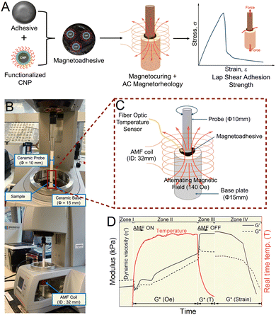
Magnetoadhesives are nascent electromagnetic materials that incorporate Curie magnetic nanoparticles (CNP) in thermoset resins to yield contactless curing under the AMF (Fig. 1A).1,2 Magnetocuring of magnetoadhesives offers remote, wireless, and touchless thermoset curing and considered as more energy efficient, since indirect substrate heating is avoided. Previous investigations of magnetocuring achieved temperature control and MPa-magnitude shear adhesion strength by (1) CNP loading, (2) elemental composition, (3) magnetic field strength, (4) electromagnetic additives based on carbon allotropes, (5) non-ferrous porous and glassy substrates, and (6) resins of varying viscosity. However, this nascent technology lacks a method to characterize the liquid to solid material properties in real-time. To address this research gap, a commercial rheometer is modified to allow measurements under alternating magnetic fields (AMFs) through a materials selection process.
This approach prioritizes non-ferrous materials for the rheometer components in contact with the magnetoadhesive, thus avoiding errant induction. AC magnetic fields of 400 kHz generated by the induction coil will induce eddy current in any ferrous material (e.g. stainless steel) and subsequently heat/melt/warp the part. To avoid thermal warping or uncontrolled induction heating, non-metallic materials are chosen, e.g., ceramics, woods, polymers, etc. for the probe and base plate. Other selection criteria include magnetic permittivity (use non-ferrous), maintain rigidity up to 200 °C (avoid thermoplastics) and be machinable into standard rheology geometries (e.g. parallel plates and cylindrical probes). Various prototypes are optimized using computer aided design (CAD) software, followed by fabrication with local machining vendors. The structure–property relationships of magnetoadhesives are evaluated for various CNP loading, rigid non-ferrous materials, and validated with 1C thermoset epoxy resins. The customized rheometer allows a comparison between conventional thermal curing and magnetocuring. For the first time, the trade-offs and advantages are discussed for magnetoadhesives with respect to automotive and carbon-fiber composite applications.
2. Materials and methods
2.1. Materials
A one-component epoxy adhesive, Permabond ES558 (referred to as ES558), is purchased from Permabond, USA. Oleic acid (OA), bisphenol A diglycidyl ether (BADGE), glycerol diglycidyl ether (GDE), ethylene diamine, manganese(II) chloride tetrahydrate (MnCl2. 4H2O, 99%), zinc chloride, anhydrous (ZnCl2, 98%), and iron(III) chloride hexahydrate (FeCl3. 6H2O) are purchased from Sigma Aldrich. Glass-reinforced plastic (GRP, 30% glass filled nylon 66), polytetrafluoroethylene (PTFE) and ceramic (MACOR) rods (10 mm and 15 mm of diameter) are purchased from RS Components, Singapore. Generic PMMA and beech wood rods are purchased through local art supply vendors.2.2. Methods
![[thin space (1/6-em)]](https://www.rsc.org/images/entities/char_2009.gif) :
:![[thin space (1/6-em)]](https://www.rsc.org/images/entities/char_2009.gif) 1 mol ratio of glycerol diglycidyl ether epoxy (68 mg) and ethylene diamine hardener (20 mg) is mixed followed by the addition of the CNP. This composition is mixed using a spatula for 10 s followed by a vortex mixer for 10 s.
1 mol ratio of glycerol diglycidyl ether epoxy (68 mg) and ethylene diamine hardener (20 mg) is mixed followed by the addition of the CNP. This composition is mixed using a spatula for 10 s followed by a vortex mixer for 10 s.
| M s (emu g−1) | H c (Oe) | M r (emu g−1) | M r/Ms | K × 104 (J m−3) | T B (K) @ 100, 200 Oe | T irr (K) @ 100, 200 Oe |
|---|---|---|---|---|---|---|
| 66 | 16.5 | 2.25 | 0.034 | 2.43 | 393, 301 | 400, 379 |
3. Results
3.1. AC magnetorheometry design: pairing AMF coils and substrates
Measuring the real-time viscoelastic properties of magnetoadhesives is required to evaluate the dynamic viscosity, complex modulus, gelation point, and shear stress/strain at failure. The conventional rheometer accessories are limited to static magnetic fields and cannot be AMF retrofitted. Another consideration is the probe geometry. A concentric cylinder (Couette system) probe/base offers the homogenous AMF sample exposure using standard cylindrical coils. However, the cured epoxy resin would necessitate destroying the machined probes. A cone–plate geometry is not advised for particulate suspensions and requires high tolerance machining (±5 μm). The parallel plate probes/plates are determined to have the best combination of attributes in terms of machining cost, sample volume, durability, and interfacing with both cylindrical and pancake AMF coils. The parallel plate rheometery is refined for the AMF by:(a) Non-metallic and non-magnetic material selections,
(b) Interfacing and testing both solenoid/pancake coil geometries,
(c) Suppressing magnetic fields away from sensitive rheometer components/electronics,
(d) High sample throughput without damage to probes or rheometer.
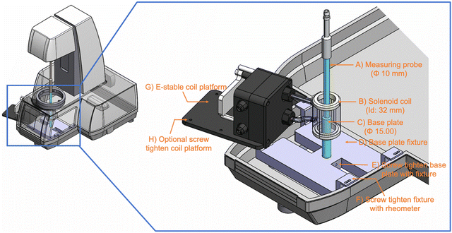
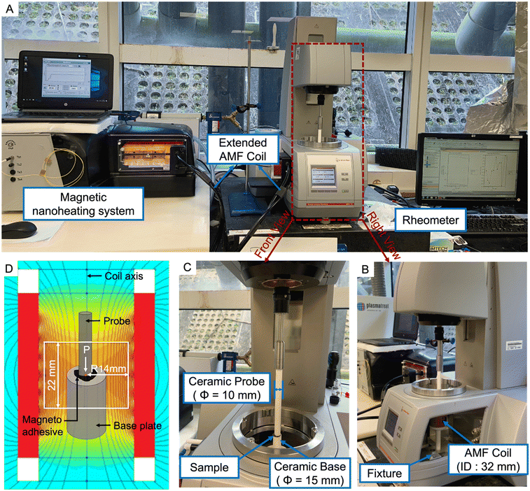
To achieve the aforementioned objectives, the parallel plate and base are machined from ceramics, woods, and rigid plastics. The CAD software is used to ensure the space tolerances of assembly within the aluminium rheometer cavity. The representative CAD drawings of the rheometer are shown in Fig. 2 and Fig. S1 and S2, ESI.†Fig. 3 shows how the magnetic generator is interfaced to the rheometer, base plate, probe, and induction coil. Fig. 3D shows the field distribution in the solenoid coil (S32, nB nanoscale Biomagnetics). The field is normalized to the reference point (P), where the field is maximum at the axis.
Non-specific induction heating of the aluminium rheometer could induce thermal expansion and structure warping, so preliminary testing examined temperature changes. No induction heating of aluminium alloy is observed within 2–5 cm of the solenoid coil at a maximum power (140 Oe), as shown in Fig. S3, ESI.† The AC magnetorheometry of magnetoadhesive composites composed of varying weight ratios of the CNP and epoxy adhesive is evaluated before (control), during, after AMF exposure (cooling), and then elongated until failure. The storage modulus (G′) and loss modulus (G′′) are evaluated in four zones (Fig. 1D):
Zone I for 60 s with the AMF OFF (control).
Zone II: The AMF ON for 3000 s,
Zone III: The AMF OFF with sample cooling for 1200 s;
Zone IV: Amplitude sweep from 0.1 to 1000% strain.
3.2 Substrate materials alter the gelation time and modulus
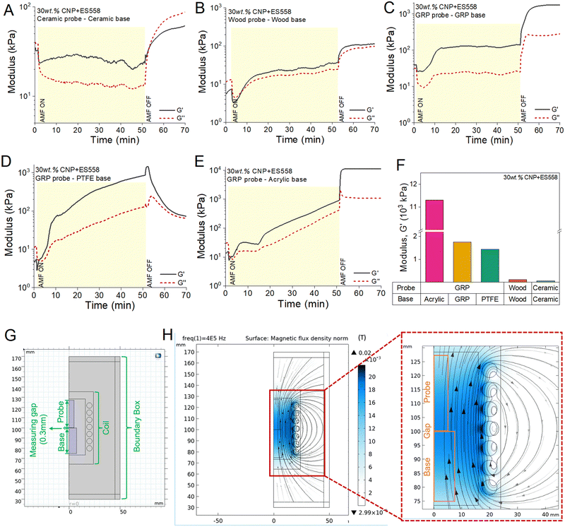
Earlier reports on magnetocuring provided the proof-of-concept results using a commercial epoxy adhesive (Permabond ES558), a known, epoxy resin + hardener recipe, and Curie temperature (Tc) controlled magnetic nanoparticles (CNP).1,2 The Curie temperature is tuned to exceed the activation temperature, but lower than the thermal instability temperature of the epoxy thermosets. Mn/Zn doped CNP are preferred for AMF induction heating compared to metallic magnetic nanoparticles due to the convenient selection of these failsafe temperature limits. Metallic magnetic particles exhibit a larger magnetic moment compared to the oxide particles (CNP) and higher heat generation at lower concentrations. However, the dispersion of metallic particles is challenging, especially in organic solvents. A SAR of 450 Wg−1 is reported for Fe–Co particles, which is higher compared to the corresponding values of oxide particles (<100). The maximum power loss occurs at a particle size of ∼35 nm.23 Such particles are not suitable for magnetocuring, and their high Curie temperature would induce thermoset pyrolysis and degradation. This serves as the rationale for choosing Mn/Zn doped CNPs for thermoset activation. The measuring probe and base plate materials are evaluated with respect to Young's modulus, dielectric constant, and thermal conductivity (Fig. 4). Five combinations of probe and base plate are chosen: (i) a ceramic probe with a ceramic base plate (Fig. 5A); (ii) a wood probe with a wood base plate (Fig. 5B); (iii) a glass reinforced plastic (GRP) probe with a GRP base plate (Fig. 5C); (iv) a GRP probe with a polytetrafluoroethylene (PTFE) base plate (Fig. 5D); and (v) a GRP probe with an acrylic base plate (Fig. 5E). The gelation time (defined as G′ = G′′, crossover point) for all the samples is observed within 1 min upon applying the AMF, except for the ceramic for which the magnetoadhesive takes more time (1.42 min) to start crosslinking. The cured G′ appears to correlate with the thermal conductivity of the probe and base plates as shown in Fig. 4. The storage moduli for different materials are compared in Fig. 5F and observed to decrease in the following order:| GRP–acrylic > wood–wood > GRP–GRP > GRP–PTFE > ceramic–ceramic |
 | ||
| Fig. 4 Materials selection matrix for AC magnetorheometry designing. (A) Modulus vs. thermal conductivity. (B) Density vs. dielectric constant. | ||
COMSOL simulations are performed to determine the effect of varying dielectric constant and composition of probe/base materials on magnetic field attenuation under the AMF. The simulations are performed with a 408 kHz of frequency and a 7-turn solenoid coil, which represents ∼140 Oe of the magnetic flux density. A homogeneous magnetic flux density is observed in all the probe/base materials (Fig. 5G, H and Fig. S4, ESI†).
3.3. Magnetocuring adhesive composite crosslinks within 1 min
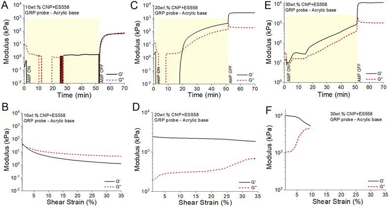
Real-time AC-magnetorheometry (AC-MR) serves to determine the structure–property relationships of the commercial epoxy adhesive with the increasing concentration of the CNP. Fig. 6 summarizes the oscillation and amplitude sweep results of epoxy adhesives with 10, 20 and 30 wt% loading of the CNP on an acrylic base plate and a glass-reinforced probe (GRP) measuring probe. The composite with the CNP (10 wt%) starts crosslinking within 8 min upon applying an AMF of 140 Oe and reaches a storage modulus (G′) of 65 kPa after cooling (Fig. 6A). The amplitude sweep reveals a relatively low yield stress, indicative of incomplete crosslinking, Fig. 6B. Increasing the CNP loading up to 20 wt% results in crosslinking in 2.1 min and a G′ of 2715 kPa (Fig. 6C and D). This improves to <1 min and a G′ of ∼11 MPa is achieved with 30 wt% loading of the CNP (Fig. 6E and F).The linear viscoelastic range (LVR) is evaluated with amplitude sweeps ranging from 0.1 to 1000% strain and is performed after cooling to room temperature (Fig. 6B, D and F). The dynamic viscosity and gelation time of the magnetoadhesive with different loadings of the CNP are compared in Fig. S5, ESI.† The 10 wt% CNP magnetoadhesive becomes a Bingham plastic with a 2% yield strain. Magnetoadhesives with 20 and 30 wt% of the CNP exhibit elongations of 34% and 9%, respectively.
3.4. G* and curing are dependent on substrate thermal conductivity
Prior to AMF exposure, the apparent viscosities of all formulations are below 500 Pa s (Fig. 7A). The temperature probe is placed within 1 mm of the probe per sample surface (Fig. 1B). A maximum temperature is reached within 10 min and correlates to % CNP loading. Magnetoadhesives with 10, 20 and 30 wt% CNP loading reached up to 47 °C, 59 °C and 89 °C, respectively (Fig. 7A). The probe–base plate temperature profiles correlate with the thermal conductivity, density, and thermal stability of the materials. The magnetoadhesive for acrylic, wood and GRP base plates shows a maximum temperature of 89 °C. For PTFE and ceramic base plate, maxima of 80 °C and 64 °C, respectively, are reached. (Fig. 7B).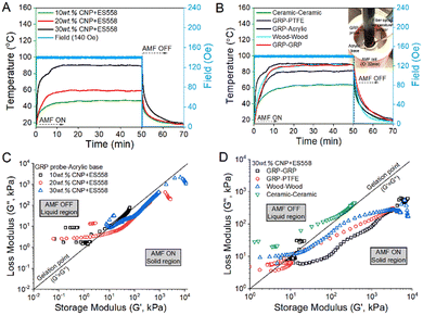 | ||
| Fig. 7 Dynamic rheological properties of magnetoadhesives at 140 Oe. (A and B) Real-time AMF heating temperature profile of magnetoadhesives during magnetorheometry (Fig. 7A and B represents the temperature profile corresponding to Fig. 6 and 5A–E, respectively). (C and D) Complex modulus plot of different CNP loadings in the adhesive and varying base plates. | ||
After switching off the AMF, the temperature decreases to 30 °C within 5 min (Fig. 7A and B). The magnetorheometry data is represented as vector plots of the loss modulus (G′′) vs. storage modulus (G′), allowing comparison of the transition of the complex modulus (G*). Fig. 7C displays the complex modulus as a function of CNP loading. The G′′ vs. G′ vector map shows the transition of G* from the viscous region (G′′ > G′) to the solid/crosslinked region (G′′ < G′). However, G* of 10 wt% CNP never achieves complete gelation, likely due to the complete crosslinking of the epoxy matrix. This phenomenon corresponds to insufficient heating, as the resin only achieved a measured temperature of 40 °C. Fig. 7D compares the effect of the four combinations of probe/base plate materials on G*. Measuring probe and base plates with lower thermal conductivity (GPR, wood, and acrylic) facilitates magnetocuring.
3.5. Optimized thermoset cures on ceramics up to a G′ of 4 MPa
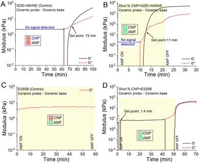
Control experiments with the mixture of epoxy + hardener are performed to check the accuracy of the setup and the effect of AMF exposure. Glycerol diglycidyl ether (GDE) and ethylene diamine are mixed in a 1![[thin space (1/6-em)]](https://www.rsc.org/images/entities/char_2009.gif) :
:![[thin space (1/6-em)]](https://www.rsc.org/images/entities/char_2009.gif) 1 mol ratio at room temperature and rheometry is performed with 20 mL of the sample in the absence of a magnetic field and the CNP (Fig. 8A). The gelation time is observed to be 72 min and the storage modulus reaches up to ∼60 kPa. However, upon AMF exposure, a faster gelation time (within 11 min) and a high storage modulus of ∼4 MPa are achieved for the 20 wt% CNP composite (Fig. 8B).
1 mol ratio at room temperature and rheometry is performed with 20 mL of the sample in the absence of a magnetic field and the CNP (Fig. 8A). The gelation time is observed to be 72 min and the storage modulus reaches up to ∼60 kPa. However, upon AMF exposure, a faster gelation time (within 11 min) and a high storage modulus of ∼4 MPa are achieved for the 20 wt% CNP composite (Fig. 8B).
Another control with the commercial adhesive ES558 shows no crosslinking under the magnetic field, with zero CNP (Fig. 8C) while the presence of the CNP results in a faster gelation (within 1.4 min) but incomplete crosslinking even after 50 min of AMF exposure due to the higher thermal conductivity of the ceramic probe/base (Fig. 8D).
4. Discussion
For thermosets–epoxy adhesives used in industrial applications, rheology is necessary to evaluate the processing parameters, flow rate, cure cycle, and to verify the quality of the final product. It also reveals how variables such as cure cycle, temperature, time, composite formulation, and deformation rate affect the material properties. Magnetoadhesives are emerging materials which offer an energy efficient and touchless method of curing under the AMF.1,2 The activation of magnetocuring adhesive–epoxy thermosets can be achieved within ∼5 min via Curie nanoparticles acting as magnetic/thermal transducers. Magnetocuring offers improvements over other stimuli-sensitive formulations, such as snap-curing,24 photocuring,25 electrocuring,26 and electron-beam curing.27Magnetocuring was first demonstrated on non-metallic substrates (wood, plastic, and glass) that allowed an adhesion strength up to ∼7 MPa for wood at a heating rate of ∼1.2 °C s−1.1 The heating rate was further improved by increasing the manganese content in the CNP and incorporating electromagnetic additives into the resin.2 The rheological properties of magnetoadhesives were determined in this study by coupling a commercial rheometer and a AMF system. By an appropriate use of the solenoid coil, rheometer probe and base plate, the magnetocuring process could be tracked in real time. The AC-magnetorheometer and its components are presented in Fig. 2 and 3.
The magnetocuring of epoxy adhesives relies on the AMF induction heating, where the CNP serves as the magnetic field to heat the transducer. When the AMF is applied, these nano-inductors heat the resin above its thermoset activation temperature but the final temperature is lower than the pyrolysis temperature. Higher loading of the CNP increases the storage modulus and results in faster gelation times. Due to the higher loading of the CNP, the heating rate increases, which results in crosslinking initiation within 0.35 min of applying a 140 Oe AMF. The structure–activity relationship of AC-magnetorheometry was studied with a range of non-metallic materials as the base plate and measuring probe. The materials chosen have a similar magnetic permeability, but vary in thermal conductivity and dielectric constant. The highest G′ (∼11 MPa) and quick gelation (1 min) were achieved with an acrylic base plate and glass reinforced plastic measuring probe. The rheological properties and thermal conductivity of all the materials are tabulated in Table 2.
| Material (measuring probe–base plate) | Thermal conductivity of base plate (W mK−1) | Storage modulus (kPa) | Gelation time (min) |
|---|---|---|---|
| GRP–acrylic | 0.2 | 11378 | 0.95 |
| Wood–wood | 0.12 | 7775 | 0.35 |
| GRP–GRP | 0.3 | 7559 | 0.13 |
| GRP–PTFE | 0.3 | 4512 | 0.58 |
| Ceramic–ceramic | 1.5 | 186 | 1.42 |
Wood with a low thermal conductivity resulted in a faster gelation within 0.35 min. The higher thermal conductivity of ceramic results in a lower G′ (0.2 MPa) and a delay in gelation (1.4 min). The machinable ceramic is composed of ∼55% mica and ∼45% borosilicate glass. The presence of ∼2.5% ferric oxide in mica may result in some degree of magnetic field attenuation, and consequently lower the G′. This hypothesis was tested by performing magnetic field-frequency domain COMSOL simulations, which reveal a homogeneous field distribution in the ceramic. PTFE and GRP have similar thermal conductivities (0.2 W mK−1), and the GRP results in the fastest gelation (0.13 min) and high G′ (7.5 MPa). The low storage modulus (4.5 MPa) and delay in gelation (0.58 min) for PTFE could be due to its non-stick characteristics and low friction properties. After switching off the AMF, the sample modulus on PTFE immediately decreases, unlike all other materials. Acrylic as the base plate shows the gelation of the magnetoadhesive within 1 min and reached the highest G′ (∼11 MPa). The acrylic base was also studied for the DICY adhesive system (epoxy-amine) and showed a high G′ of ∼4 MPa, consistent with the result obtained for the commercial adhesive, ES558. Tensile testing was performed for the magnetocured samples after AC magnetorheology. The cured samples and lap shear adhesion strength are presented in Fig. 6, ESI.† The wood–wood and GRP–acrylic combinations show cohesive failures at 4 MPa and 3 MPa, respectively, while the GRP–acrylic bond breaks at 4.5 MPa.
AC-magnetorheometry aims to be a valuable evaluation method for the investigation of not only thermosets, but also other CNP/polymer composites. With the optimized experimental set-up (Fig. 1), the analytical method allows the multimodal characterization of viscoelastic CNP composites, such as:
(1) Dynamic viscosity (G′′/ω or η′) analysis at low strain rates, (2) G′ as a function of CNP loading and AMF exposure, (3) G′ dependence on probe/base substrates and geometry, (4) determination of the gelation time/Joules exposure (G′ = G′′), and (5) complex modulus (G*) vector map from liquid to solid.
Future work will address the detailed microscopic analysis of magnetocured samples during/after AC-magnetorheometry, examining the relationship between the adhesion and magnetic phenomena by performing probe-tack tests. The presented real-time AC-magnetorheometry can be integrated for industrial applications/testing of adhesives, where the real-time properties concerning pre-processing conditions, quality control, temperature sensitivity, and cure cycle are required in diverse fields such as automotive manufacturing and carbon–fibre composite production.
5. Conclusions
The viscoelastic properties of magnetocuring adhesives under alternating magnetic fields (AMFs) are analysed instantaneously for the first time. AC-magnetorheometry determined the necessary curing characteristics required for the industrial application of magnetoadhesives. The gelation time is achieved in less than 1 min by applying alternating magnetic fields (400 kHz @ 140 Oe) with a final storage modulus of 11 MPa. The efficiency of magnetocuring and AC-magnetorheometry is demonstrated on a variety of non-ferrous materials, including plastics, woods, and ceramics. The novel AC-magnetorheometry technique can be expanded to study the viscoelastic rheological properties of electromagnetic materials such as carbon fiber composites, metal organic frameworks, and liquid alloys.Conflicts of interest
The authors declare no conflicts of interest.Acknowledgements
This work was financially supported by the Agency for Science, Technology and Research (A*Star) IRG17283008 “Microprocessor-based methods of composite curing”.References
- R. Chaudhary, V. Chaudhary, R. V. Ramanujan and T. W. Steele, Appl. Mater. Today, 2020, 21, 100824 CrossRef.
- R. Chaudhary, V. Chaudhary, Y. Suda, R. V. Ramanujan and T. W. Steele, Adv. Mater. Interfaces, 2021, 8, 2100881 CrossRef CAS.
- K. Miller, K. Collier, H. Soll-Morris, R. Swaminathan and M. McHenry, J. Appl. Phys., 2009, 105, 07E714 CrossRef.
- V. Chaudhary and R. Chaudhary, Encycl. Nanosci. Nanotechnol., 2018, 28, 153–183 Search PubMed.
- O. L. Lanier, O. I. Korotych, A. G. Monsalve, D. Wable, S. Savliwala, N. W. Grooms, C. Nacea, O. R. Tuitt and J. Dobson, Int. J. Hyperthermia, 2019, 36, 686–700 CrossRef CAS PubMed.
- J. Jose, R. Kumar, S. Harilal, G. E. Mathew, A. Prabhu, M. S. Uddin, L. Aleya, H. Kim and B. Mathew, Environ. Sci. Pollut. Res., 2020, 27, 19214–19225 CrossRef PubMed.
- H. Chen, D. Billington, E. Riordan, J. Blomgren, S. R. Giblin, C. Johansson and S. A. Majetich, Appl. Phys. Lett., 2020, 117, 073702 CrossRef CAS.
- A. Habib, C. Ondeck, P. Chaudhary, M. Bockstaller and M. McHenry, J. Appl. Phys., 2008, 103, 07A307 CrossRef.
- C. Ondeck, A. Habib, P. Ohodnicki, K. Miller, C. Sawyer, P. Chaudhary and M. McHenry, J. Appl. Phys., 2009, 105, 07B324 CrossRef.
- R. Das, J. A. Cardarelli, M.-H. Phan and H. Srikanth, J. Alloys Compd., 2019, 789, 323–329 CrossRef CAS.
- S. D. Anderson, V. V. Gwenin and C. D. Gwenin, Nanoscale Res. Lett., 2019, 14, 1–16 CrossRef CAS PubMed.
- J. Dobson, Nat. Nanotechnol., 2008, 3, 139–143 CrossRef CAS PubMed.
- V. Chaudhary, Z. Wang, A. Ray, I. Sridhar and R. Ramanujan, J. Phys. D: Appl. Phys., 2016, 50, 03LT03 CrossRef.
- D. E. Bordelon, C. Cornejo, C. Grüttner, F. Westphal, T. L. DeWeese and R. Ivkov, J. Appl. Phys., 2011, 109, 124904 CrossRef.
- V. A. Sharapova, M. A. Uimin, A. A. Mysik and A. E. Ermakov, Phys. Met. Metallogr., 2010, 110, 5–12 CrossRef.
- A. Paar, https://www.anton-paar.com/sg-en/products/details/magnetorheology/.
- A. G. Díez, C. R. Tubio, J. G. Etxebarria and S. Lanceros-Mendez, Adv. Eng. Mater., 2021, 2100240 CrossRef.
- A. K. Bastola and M. Hossain, Composites, Part B, 2020, 200, 108348 CrossRef CAS.
- N. Hapipi, S. A. A. Aziz, S. A. Mazlan, U. Ubaidillah, S. B. Choi, N. Mohamad, M. H. A. Khairi and A. Y. A. Fatah, Results Phys., 2019, 12, 2146–2154 CrossRef.
- M. A. F. Johari, S. A. Mazlan, M. M. Nasef, U. Ubaidillah, N. A. Nordin, S. A. A. Aziz, N. Johari and N. Nazmi, Sci. Rep., 2021, 11, 10936 CrossRef CAS PubMed.
- H. Böse, T. Gerlach and J. Ehrlich, J. Intell. Mater. Syst. Struct., 2021, 1045389X21990888 Search PubMed.
- J. Parameswaranpillai, N. Hameed, J. Pionteck and E. M. Woo, Handbook of epoxy blends, Springer, 2017 Search PubMed.
- A. H. Habib, C. L. Ondeck, P. Chaudhary, M. R. Bockstaller and M. E. McHenry, J. Appl. Phys., 2008, 103, 07A307 CrossRef.
- X. K. Hillewaere, R. F. Teixeira, L. T. T. Nguyen, J. A. Ramos, H. Rahier and F. E. Du Prez, Adv. Funct. Mater., 2014, 24, 5575–5583 CrossRef CAS.
- S. C. Ligon-Auer, M. Schwentenwein, C. Gorsche, J. Stampfl and R. Liska, Polym. Chem., 2016, 7, 257–286 RSC.
- J. Ping, F. Gao, J. L. Chen, R. D. Webster and T. W. Steele, Nat. Commun., 2015, 6, 1–9 RSC.
- R. Rizzolo, D. Walczyk and J. Kuppers, Proc. Inst. Mech. Eng., Part B, 2019, 233(4), 1168–1181 CrossRef.
Footnote |
| † Electronic supplementary information (ESI) available: Supplementary Fig. S1–S6, Table S1. See DOI: https://doi.org/10.1039/d2ma00473a |
| This journal is © The Royal Society of Chemistry 2022 |

