 Open Access Article
Differentiating chemical and electrochemical degradation of lithium germanium thiophosphate and the role of atomic layer deposited protection layers†
Yang
Wang
 a,
Sam
Klueter
b,
Myungsuk
Lee
f,
Junnyeong
Yun
f,
Binh
Hoang
 d,
Elias
Kallon
b,
Cholho
Lee
 c,
Chuan-Fu
Lin
d,
Gary W.
Rubloff
 be,
Sang Bok
Lee
 *ab and
Alexander C.
Kozen
 *be
*be
aDepartment of Chemistry and Biochemistry, University of Maryland, College Park, MD, USA. E-mail: slee@umd.edu
bDepartment of Materials Science & Engineering, University of Maryland, College Park, MD, USA. E-mail: ackozen@umd.edu
cSK On Co., Ltd. 26, Jongno, Jongno-gu, Seoul, Korea
dDepartment of Mechanical Engineering, Catholic University of America, Washington, DC, USA
eInstitute for Systems Research, University of Maryland, College Park, MD, USA
fInstitute of Technology Innovation, SK innovation, Daejeon, South Korea
First published on 16th September 2022
Abstract
Li10GeP2S12 (LGPS) is a superionic conductor that has an ionic conductivity equivalent to conventional liquid electrolytes (∼10−2 S cm−1) and thus shows exceptional potential to fulfill the promise of solid-state batteries. Nonetheless, LGPS is chemically and electrochemically unstable against Li metal, decomposing into the thermodynamically favorable byproducts of Li3P, Li2S, and alloyed LixGe. Contact between Li metal and LGPS results in formation of high impedance interphase layers due to lithium diffusion into and subsequent reaction with the LGPS structure. Artificial solid electrolyte interphase (ASEI) layers are a promising route to mitigate and reduce the chemical reactivity of the LGPS surface. Here, we differentiate between static chemical degradation induced by LGPS-Li contact, from electrochemical degradation induced via galvanostatic cycling of Li/LGPS/Li cells as critical to rational ASEI evaluation. From this perspective, we utilize a thin ASEI coating of lithium phosphorous oxynitride (LiPON), deposited by atomic layer deposition (ALD), to mitigate both chemical and electrochemical degradation at the Li/LGPS interface.
Introduction
In the early 1990s Sony commercialized the first Li-ion batteries, which have subsequently dominated the portable electronic device market and are now powering the burgeoning electric vehicle market.1–3 However, significant concerns relating to the flammability of liquid electrolytes are one of the primary drivers of the search for solid state electrolyte (SSE) materials.1–3 While many SSEs have much lower ionic conductivity than conventional liquid electrolytes, Li10GeP2S12 (LGPS), first reported by Kamaya et al. in 2011, has an exceptionally high ionic conductivity of 1.0 × 10⁻² S cm−1.4 Despite its high ionic conductivity, LGPS suffers from chemical instability with both Li metal anodes and high voltage Li-ion cathode materials, dramatically reducing the efficiency of battery systems based on LGPS.5–10Computational studies have shown that the thermodynamic electrochemical stability window of LGPS is only from 1.7 V to 2.5 V (vs. Li+/Li), narrower than many other SSE materials, thus offering the Faustian trade-off of high ionic conductivity for low voltage stability.11–13 At anodic potentials below 0.6 V (vs. Li+/Li), the Ge in LGPS will alloy with Li and produce an electronically conductive LixGe alloy, which is a mixed ion-electron conductor (MIEC) resulting in continuous degradation and facilitating the growth of Li dendrites.13–16 On the cathode side, typical metal oxide cathode materials will spontaneously react with LGPS to form metal sulfides, also developing a non-passivating MEIC interphase and ultimately increasing overall cell impedance.12,17–20
There are two competing degradation mechanisms in LGPS-based cells: electrochemical degradation that occurs during battery cycling, and thermodynamic degradation that occurs both during battery cycling but also during battery rest. Multiple approaches have been developed to mitigate electrochemical LGPS degradation such as isoelectric substitution of Ge and P or halogen doping to form more stable SEI by-products,8,18,21–26 or deposition of an artificial SEI (ASEI) coating directly onto LGPS to bridge the electrochemical stability gap.21,27–30 Even though there have been studies about thermodynamic degradation in the field of Si anodes,31,32 few reports have dived into the investigation of Li/LGPS system or deconvolute static vs. dynamic decomposition and thus miss the dramatic impact of static decomposition.
As we seek to understand the impact of ASEI layers on mitigating both types of Li–LGPS decomposition, we utilized a prototypical ASEI material, lithium phosphorous oxynitride (LiPON), deposited by atomic layer deposition (ALD). ALD is a well-established method extensively used in the semiconductor industry to produce chemically tuneable, highly conformal films with atomic-scale thickness control. ALD has been used to deposit ASEI layers for chemical protection of graphite anodes,33,34 Li metal anodes,35–39 cathodes,40–46 and other solid electrolyte pellets.47
We select LiPON as an ASEI due to its large electrochemical stability window (5.5 V vs. Li+/Li), allowing use with both high voltage cathodes and Li metal anodes, and an acceptable ionic conductivity of ∼10−6 S cm−1. We have previously developed an ALD-LiPON process by using lithium tert-butoxide (LiOtBu), H2O, trimethyl phosphate (TMP), and plasma N2 as precursors.48
In this work, we apply a thin ASEI layer of ALD LiPON directly on the surface of LGPS pellets, demonstrating the effect of mitigating the interfacial degradation reactions between Li and LGPS at moderate current density electrochemical cycling. We qualitatively deduced the components of the degradation reactions by studying the chemical aging of the Li/LGPS interface by direct contact, while complementary computational studies were employed to elucidate the effect of the ALD LiPON layer on the chemical and electrochemical degradation reactions. These data relay fundamental insights into chemical and electrochemical degradation at the Li/LGPS interface, with significant implications on the storage, preservation, and future surface protection strategies in the practical application of the sulfide-based solid-state electrolytes.49
Results & discussion
XPS analysis
Fig. 1 shows high-resolution XPS data of the LGPS pellet surface before, after 10 nm ALD LiPON, and after 20 nm ALD LiPON depositions at 250 °C. 10 nm ALD LiPON is thin enough that the photoelectrons have an escape depth comparable to the film thickness, as such the chemistry of the LGPS/LiPON interface can be interrogated. 20 nm ALD LiPON is thick enough that all photoelectrons escape from the bulk of the LiPON layer itself, eliminating any signal from the LGPS or LGPS/LiPON interface. The Li 1s high resolution region, Fig. 1a, indicates a single Li peak consistent with Li2CO3 on the surface of the LGPS, which is replaced by LiPON-like bonding at 55.2 eV and appears homogenous at the interface and in the bulk of the LiPON layer. Fig. 1b shows the Ge 3d region, where a single Ge4+ peak is buried under the ALD LiPON layer. After 10 nm LiPON deposition, the Ge4+ peak shifts to slightly lower binding energy, consistent with Ge4+ to Ge3+ reduction previously reported as due to LixGe alloying.25,50Fig. 1c shows the P 2p region, where a single doublet consistent with LGPS is replaced by a single doublet consistent with ALD LiPON at 20 nm thick. The 10 nm thick trace shows a broad peak of intermediate binding energy between LGPS and LiPON, consistent with a graded material. Fig. 1d shows the S 2p region. Starting with an initial P 2p doublet we attribute to PS43− on the LGPS surface, 10 nm of ALD LiPON is clearly seen to oxidize the LGPS, forming SO42− and SO32− groups at the LGPS/LiPON interface. We attribute this oxide formation at the LiPON/LGPS interface as the source of high initial impedance in ALD LiPON-coated LGPS pellets. Additionally, Fig. 1d shows there is some evidence of Li2S formation at this interface. 20 nm ALD LiPON shows a dramatically reduced sulfur signal, predominantly composed of some elemental sulfur, likely due to some mixing of sulfur at the LGPS/LiPON interface. The C 1s region, shown in Fig. 1e, shows some Li2CO3 formation at the LGPS/LiPON interface after 10 nm ALD LiPON deposition, however 20 nm ALD LiPON dramatically reduces the peak associated with Li2CO3. Additionally, thicker 20 nm ALD LiPON layers show a second peak at 288 eV we associate with –CO bonding, likely due to some unreacted ALD precursor ligands. The O 1s region, shown in Fig. 1f, indicates the surface of LGPS is relatively oxygen-free before ASEI layer deposition. After 10 nm ALD LiPON, an O 1s peak associated with P![[double bond, length as m-dash]](https://www.rsc.org/images/entities/char_e001.gif) O bonding in LiPON emerges at 531.5 eV. This peak is maintained when 20 nm ALD LiPON is deposited, in addition to a second peak associated with –CO bonding.
O bonding in LiPON emerges at 531.5 eV. This peak is maintained when 20 nm ALD LiPON is deposited, in addition to a second peak associated with –CO bonding.
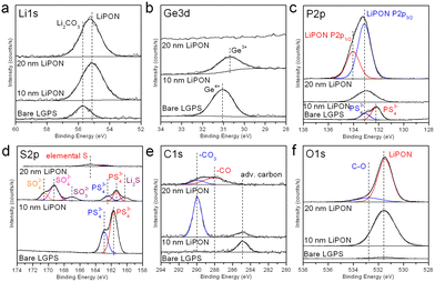 | ||
| Fig. 1 High resolution (a) Li 1s; (b) Ge 3d; (c) P 2p; (d) S 2p; (e) C 1s; (f) O 1s XPS figures of bare, 10 nm ALD LiPON coated, and 20 nm ALD LiPON coated LGPS pellets. | ||
Cyclic voltammetry and electrochemical impedance spectroscopy analysis
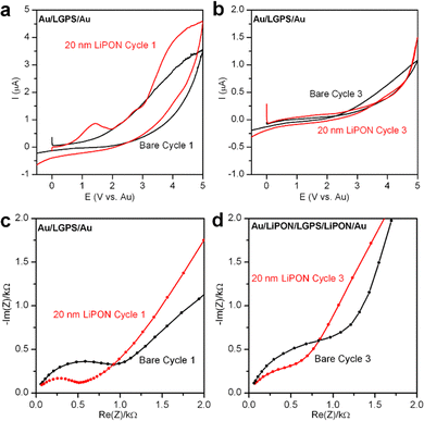
In order to understand the electrochemical stability of both LGPS and the role LiPON plays as an ASEI, without the additional reactivity of Li metal electrodes, we closed Au/LGPS/Au symmetric cells and tested a sequence of EIS + CV measurements to monitor the degradation reactions and change in impedance as these cells were subjected to voltage sweeps up to 5 V. In this configuration, no additional source of Li is available to react with the LGPS, ensuring we only investigate the inherent voltage stability of the bare and LiPON-coated LGPS pellets.28 To improve contact resistance with the testing cell electrodes, 200 nm Au was sputtered on both sides of the LGPS pellets prior to testing.The first and last CV sweeps are shown in Fig. 2a and b, respectively. In Fig. 2a, the bare LGPS starts to exhibit electrochemical decomposition at ∼1.5 V, which increases in magnitude with increasing voltage. When coated with 20 nm LiPON, there is a sharp peak at 1.5 V, which we associate with LiPON-LGPS interface reactions forming Li2O and Li2S. Additionally, LiPON-coated LGPS cells exhibit similar decomposition behavior of the LGPS itself. Fig. 2b shows the 3rd CV cycle of the Au/LGPS/Au cells. Here, resistive degradation byproducts have formed due to voltage-induced decomposition at both electrode-LGPS interfaces. However, the bare LGPS pellet exhibits continued degradation above 2 V, while LiPON-coated LGPS cell exhibits increased voltage stability due to the potential drop across the LiPON layer subjecting the LGPS to lowered field strength. However, in both cases electrochemical degradation is irreversible, and the reaction byproducts, while thin, are insulating. This is supported by the data presented in Fig. 2c and d: EIS plots of the same Au/LGPS/Au cells before any and after 3 CV sweeps from −0.5 V to 5 V. In both the bare and LiPON-coated LGPS cases, the initial impedance is lower than that of the cycled cells, but not dramatically so, indicating the relative stability of the LGPS without additional available Li to form the fully lithiated degradation products. However, the LiPON-coated cells exhibit a stable Warburg diffusion tail both before and after cycling, while the bare LGPS shows evidence of additional capacitive behavior in the low frequency diffusion tail, potentially indicative of more severe degradation of the bare LGPS pellets themselves.28
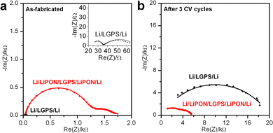
To further investigate the degradation reactions between Li metal and LGPS, and to investigate if a thin LiPON ASEI coating can mitigate such effects, reactive Li metal electrodes were used in a symmetric Li/LGPS/Li testing configuration. The first (as-fabricated) and last cycles of EIS spectra of Li/LGPS/Li cells with bare and 20 nm LiPON coated LGPS pellets are displayed in Fig. 3a and b. EIS was measured before and after each of three CV sweeps from −0.5 to 5 V (not shown). Clearly, the bare LGPS exhibits significantly lower impedance when the cells are first assembled, as LGPS has much higher ionic conductivity than LiPON. Given reasonable ionic conductivies of the LiPON and LGPS, and their associated thicknesses, we would expect the initial impedance of the LiPON-coated LGPS to be in the 10 Ω range. However, the intial impedance of the LGPS pellets coated with ALD LiPON is in the kΩ range, significantly higher than would be expected if there were no chemical interaction between LiPON and LGPS layers. We attiribute this higher than expected initial impedance to deleterious interfacial chemical reactions occuring during the LiPON ALD process, further supported by the data shown in Fig. 1. However, after 3 CV sweeps, the impedance of the bare LGPS cell increased by almost 350 times to 14 kΩ. In contrast, the cell with 20 nm LiPON coated LGPS has higher initial impedance than bare LGPS, but the impedance only increases by 3.5 times to 5 kΩ after three CV sweeps, and as such the impedance of the 20 nm LiPON coated LGPS is significantly below that of bare LGPS. As Fig. 2c and d have shown that LGPS itself and LGPS/LiPON interface are generally stable without contacting Li metal, this drastic increase in impedance shown in Fig. 3 is entirely due to the degradation reactions at Li/LGPS interface. This dramatic evidence shows that a 20 nm LiPON coating can mitigate the degradation reactions at the Li/LGPS interface by reducing the effective potential at the surface of the LGPS.
Galvanostatic charging and discharging
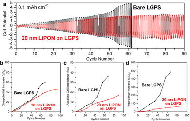
Galvanostatic charging and discharging testing can provide an alternative to CV stability testing by supplying a constant current and measuring the resulting cell overpotential. We assembled the same Li/LGPS/Li cells with bare and 20 nm LiPON coated LGPS pellets and conducted galvanostatic charging and discharging at a charge capacity of 0.1 mA h cm−2 per cycle. We use this low current to prevent potential Li plating during extended cycling, as well as to limit Li to that sufficient to slowly react with the LGPS interface, allowing us to interrogate the early stages of this degradation process. EIS spectra were measured at the beginning and after every 10 cycles of electrochemical cycling to monitor the dynamic changes in cell impedance. As shown in Fig. 4a, while a 20 nm LiPON coated LGPS pellet shows slightly higher overpotential at the beginning of cycling due to the lower ionic conductivity of LiPON as compared to LGPS. Nonetheless, after just two cycles, the overpotential and impedance of the bare LGPS pellet quickly overtook the 20 nm LiPON-coated LGPS cell which then continued to rapidly increase until hitting the ±5 V voltage limit and failed on the 62nd cycle. On the other hand, the overpotential of the cell with 20 nm LiPON on LGPS increased at a slower rate and plateaued around 2.0 V around 55th cycle, until the testing was ended at 90 cycles.This trend was also reflected in Fig. 4b, which compares the cell overpotential to the initial overpotential as a function of cycle number. Fig. 4c and d compare the absolute cell impedance and increase in cell impedance versus the initial impedance between cells with bare and 20 nm LiPON coated LGPS pellets as derived from EIS data collected during the electrochemical cycling procedure. Following the trend shown in Fig. 4a and b, the cell containing 20 nm LiPON-coated LGPS had a larger initial absolute impedance (Fig. S2, ESI†) but was surpassed by the bare LGPS cell after 10 cycles. The absolute impedance of the bare LGPS cell increased at a faster rate and continued to degrade throughout the duration of cycling with a notable jump around 45 cycles. In contrast, the impedance of the 20 nm LiPON-coated LGPS cell increased at a lower rate and exhibited no signs of failure for the duration of testing. After 90 cycles, the 20 nm LiPON-coated LGPS cell still exhibited markedly lower impedance compared to the bare LGPS cell when those failed on the 62nd cycle. Both cell overpotential and impedance results indicate that thin LiPON ASEI layers, though having a lower ionic conductivity than LGPS, are effective at mitigating the interfacial degradation between Li and LGPS during electrochemical cycling by preventing the direct contact between Li and LGPS. We demonstrated that 20 nm of LiPON is thick enough to serve as an effective barrier yet also thin enough to retain an absolute overpotential and impedance lower than both bare cell's during almost the entire duration of cell cycling. Although there are degradation reactions happening at the Li/LiPON and LGPS/LiPON interfaces as shown in Fig. 3a and b, they occur at a much smaller extent than degradation at the Li/LGPS interface, allowing LiPON to bridge the voltage stability window between Li and LGPS. Similar behavior has also been reported for ALD Al2O3-coated LGPS electrolyte pellets, which, despite their lower ionic conductivity, demonstrate the importance of interface stabilization with chemically robust layers.51
Chemical aging testing
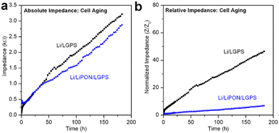
It is well accepted that upon contact, spontaneous chemical reactions occur at the Li/LGPS interface, generating Li2S among a series of other degradation products.15,28 Despite this, we have seen no prior reports evaluating and differentiating the overall contribution to cell impedance between electrochemical degradation and chemical degradation, as most reports investigating the electrochemical properties of LGPS commence electrochemical cycling immediately after cell assembly. However, this testing behavior does not adequately simulate battery performance in a realistic commercial manufacturing environment. In consideration of this fact, we assembled the same Li/LGPS/Li cells with bare and 20 nm LiPON coated LGPS pellets, measuring EIS continuously and synchronously with identical cells undergoing galvanostatic cycling for the same absolute duration of 180 hours. Using a minimal (10 mV) perturbation potential for EIS measurements minimizes any electrochemical degradation reactions as Li stripping and plating is eliminated, thus cell degradation (and associated impedance increases) is solely related to chemical reactions between Li and LGPS. We refer to this process as aging.28 As shown in Fig. 5a, the cell with LiPON had a lower impedance after aging than the bare LGPS cell despite having a higher initial impedance (Fig. S4, ESI†), indicating LiPON is also capable of suppressing the chemical degradation reactions between Li and LGPS. The ability of LiPON to mitigate aging is further demonstrated in Fig. 5b, where the LiPON-coated cell exhibited a much smaller increase (×7) in impedance over 180 hours of aging than the impedance increase of the bare cell (×46).Fig. 6 directly compares the absolute impedance increase for bare LGPS cells (Fig. 6a) and 20 nm LiPON-coated LGPS cells (Fig. 6b) undergoing electrochemical cycling and aging. For this comparison, we cycled both cells at the same 0.1 mA cm−2 current density as prior experiments, but with a lower 0.01 mA h cm−2 charge capacity per cycle, with total charge capacity being the same as cycling results shown in Fig. 4. The charge capacity per cycle for this comparison is 10× that of previous experiments, which we lowered to allow a more nuanced comparison with the chemical aging results. The cycling profiles and impedance comparison profiles can be seen in Fig. S3 (ESI†). As is clearly shown in Fig. 5a, over the course of 180 hours bare LGPS cells undergo significant degradation, with the initiation of this increased impedance over the aged sample seen at the 60th hour crossover point. There is a period at the beginning of testing where the impedance of the aging cell is higher than that of the cycling cell, followed by a crossover point where the cycling cell impedance overtakes that of the aging cell. The bare LGPS crossover point occurs just after 50 hours, while the LGPS/LiPON crossover point occurs at 80 hours into testing. We speculate this effect may be due to different chemical activity of both sides of the symmetric cell undergoing simultaneous plating and stripping of opposite electrodes during electrochemical cycling. This effect may cause only one interface to degrade – the reverse current at the other interface (i.e. Li removal from the LGPS and subsequent plating to the current collector) serves to minimize any aging occurring at this interface by driving the Li+ ions and electrons in the opposite direction from would occur during chemical aging. We recognize that this proposed mechanism is speculatory, however our results are again consistent with behavior of thin ALD Al2O3-coated LGPS electrolyte pellets.51 Furthermore, these results emphasize that during the initial break-in period, chemical degradation is the dominant degradation mechanism occurring at the Li/LGPS interface. After 180 hours the impedance contribution from chemical aging of the bare LGPS cell contributes nearly half of the total cell impedance, which is significant, and indicating that chemical aging is a competing degradation pathway from electrochemical aging. The 20 nm LiPON-coated LGPS cells, shown in Fig. 6b, show lower initial impedance for the electrochemically cycled cells than the aged cells, indicating that the LiPON coating is somewhat effective at preventing Li/LGPS reactions after initial closure of the cell. Nevertheless, there is an impedance crossover point at 80 hours where the cell undergoing electrochemical cycling increases impedance above the cell undergoing static aging testing. At 180 cycles, by comparing the impedance increase of both cells it can clearly be seen that chemical aging contributes nearly 60% of the overall cell impedance. At these higher current densities, LiPON is even more effective at mitigating electrochemical degradation during cycling than at low current densities.
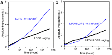 | ||
| Fig. 6 Comparison of cell impedance incurred via electrochemical cycling and via chemical aging for (a) bare LGPS cell and (b) 20 nm LiPON coated LGPS cell. | ||
Computational analysis
We attribute this phenomenon to the reduced rate of chemical reactions at Li/LiPON and LGPS/LiPON interfaces due to the higher voltage stability of LiPON than LGPS. Lastly, based on both Fig. 6a and b, the impedance during cell aging increased linearly, while the increase in impedance from electrochemical cycling accelerated over time, demonstrating two clearly different mechanisms with differing degradation kinetics. The degradation products from electrochemical cycling of LGPS are known for being mixed ionic–electronic conductors (MIEC) which do not form self-limiting reaction layers, facilitating further electrochemical degradation at the interface.13 These results from both the aging test and its comparison to electrochemical cycling are crucial, because as mere contact between Li and LGPS can induce such a large interfacial impedance, storage and handling of cells prior to testing is crucial to adequate performance, but not sufficient to develop a commercially viable Li metal anode SSB based on LGPS electrolyte.To further understand the differences between chemical and electrochemical degradation mechanisms between Li and LGPS, DFT simulations were performed for this chemical system. The chemical degradation is assumed to be a one-step reaction, where Li atom diffusion occurs across the Li/LGPS interface and subsequently reacts with the LGPS itself, forming one of many potential decomposition products. Once Li atoms (in this case a Li cation + an electron) are transferred into interstitial defect sites of the LGPS lattice, they will cleave either Ge–S or P–S bonds, producing degradation products such as Li4Ge, Li3P, and Li2S, among others.
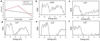
The electrochemical degradation process is assumed to follow a two-step reaction sequence, where in the first step Li cations are inserted into the LGPS near the Li/LGPS interface during charge/discharge cycling, which then form a partially positive charged LGPS as an intermediate, metastable state. In the second step, electrons from the Li metal anode are transferred to the intermediate phase, recombining with the Li cations and allowing reduction of Li metal atoms. We have calculated the relative energy pathways of both reactions, which are represented in Fig. 7a.
In the case of purely chemical degradation, we find that the energy of the LGPS system is reduced by 0.64 eV, implying that this degradation should be spontaneous. On the other hand, the first step of the electrochemical degradation has an energy increase of approximately 0.33 eV required to form the intermediate metastable phase, acting as a potential barrier to this reaction. We assume that during charge/discharge the energy required for the Li cation insertion is negligible because the Li cations are already mobile in the electrolyte under external chemical potential. Compared to the intermediate metastable phase, the energy of the second step is reduced further by 1.07 eV, indicating spontaneous decomposition from this intermediate state. Thus, although there are two similar final chemical states after chemical and electrochemical degradation of LGPS, differing energy of the reaction processes lead to the marked differences in the reaction rate shown by our experimental data. Although not explicitly discussed in this paper, similar degradation mechanisms would be expected to occur in LiPON, and indeed this is thought to be the origin of LiPON's remarkable electrochemical stability against Li metal anodes.52,53
Both LGPS and LiPON are intrinsically electrical insulators, so the electrochemical degradation reactions should be significantly suppressed during initial cycling. We thus infer that the linear degradation part of the data in Fig. 6 can be attributed to chemical degradation. After the initial cycling, the interface layer is damaged, resulting in increased electronic conductivity through this layer and subsequent uncontrolled chemical degradation. After chemical degradation in the initial cycling, the electrical conductivity of the interface materials should be changed by forming the degradation products.
To compare the electrical conductivity of the degradation products of Li with LGPS and LiPON, we represent the density of states in Fig. 7. According to the calculated results, Li4Ge is the primary electrically conductive phase (zero bandgap), while the other materials, in order of increasing bandgap are: Li3P < Li3N < Li2S < Li2O. Our results broadly agree with existing literature.54–58 Since the degradation products of LGPS include electrically conductive material, it will act as a channel for electron transfer, making suppression of the electrochemical degradation reactions challenging inside the LGPS itself. However, degradation products of LiPON contain no electrically conductive phases, and the degradation products of LiPON have higher bandgaps than those of LGPS, thus even degraded LiPON should show a higher chemical inhibition to degradation and would be sufficient to suppress the subsequent electrochemical degradation of the LGPS as shown in Fig. 6.
Experimental
LGPS pellets fabrication
Commercially available Li10GeP2S12 (LGPS) powder (MTI Corp.) was pressed into pellets using 0.120 g of powder at ∼300 MPa using a hydraulic press and a temperature-controlled die set heated to 150 °C with a diameter of 12.7 mm in an Ar-filled glove box (M-Braun). After holding at the temperature for 5 minutes, the heating program was turned off to let the die set cool down, while the pressure was maintained for a total pressing time of 45 minutes. The apparatus used and process is described in further detail elsewhere.59ALD LiPON deposition process
ALD LiPON was deposited in Veeco Fiji F200 Gen 1 ALD system using lithium tert-butoxide (LiOtBu) (Aldrich, 99.7%), deionized H2O, trimethyl phosphate (TMP) (Aldrich, 99.9%), and N2 gas (Praxair, grade 5.0). Argon (Airgas, grade 4.9) was used as a carrier gas. The base pressure of the ALD reactor was < 2 × 10⁻⁶ Torr, and a process pressure of 200 mTorr was maintained via Ar gas flow. The solid LiOtBu precursor was kept at 175 °C and was delivered to the ALD chamber using a bubbler with 40 sccm argon carrier gas flow. Samples were transferred directly from an Ar-filled glovebox through a UHV transfer system to the ALD chamber, eliminating any atmospheric exposure during ALD of ASEI layers or subsequent surface characterization.Electrochemical testing
Electrochemical cells were assembled using a 12.7 mm diameter split press cell (MTI Corp.). 0.75 mm thick Li ribbon (Alfa Aesar) was cut into 12.7 mm diameter disks with a hand punch. All cells with the same cross-sectional area were assembled symmetrically (electrode/LGPS/electrode) in an Ar-filled glove box (MBraun) for testing. Cells were held under constant pressure by a manual press to maintain good electrical contact without breaking the electrolyte pellet, with a pressure of approximately 10 MPa.Electrochemical impedance spectroscopy (EIS) testing was conducted using a Bio-Logic VSP potentiostat with a frequency range from 1 MHz to 10 mHz and a 10 mV amplitude. EIS measurements were processed and compared to simulated electrochemical circuits by EC-lab software. EIS models were fit to a circuit model containing three R/CPE components in series with each other, representing the impedance of the LGPS pellet, LGPS/Li interface, and ASEI respectively.
Cyclic voltammetry (CV) was measured by scanning the Li/LGPS/Li symmetric cells with a voltage window from +5.0 V to −0.5 V (vs. Li+/Li) and a scan rate of 0.1 mV s−1. The cells were alternately EIS + CV alternately over time and a total of four cycles of EIS and three cycles of CV were run. For control study of Li/LGPS interface, LGPS pellets, with or without LiPON coating, that were coated with ∼200 nm of gold on both sides using an AJA ATC 1800 Sputtering tool were assembled with stainless steel (ss) disks in symmetric ss/Au/LGPS/Au/ss cells and tested in the same manner.
Galvanostatic charging and discharging testing was done by cycling the Li/LGPS/Li symmetric cells at 0.1 mA cm−2 current density with a compliance voltage window of −5 V to +5 V (vs. Li+/Li). For each charging or discharging process, the hold times are 6 min with a charge capacity per half cycle at 1 × 10⁻² mA h cm−2, or 1 h with a charge capacity per half cycle at 0.1 mA h cm−2. EIS was run at the beginning and after every 100 cycles of electrochemical cycling for 6 min hold time, or after every 10 cycles for 1 h hold time. Longer term cycling results in a total of 10 EIS cycles and 1000 cycles of galvanostatic cycling with 6 min hold time per half cycle, or 100 cycles with 1 h hold time.
Chemical aging was done by continuous EIS testing on Li/LGPS/Li symmetric cells, with a frequency range from 1 MHz to 10 mHz and a 10 mV amplitude. For the first 16 EIS cycles, there was no rest period in between each measurement. For the next 16 EIS cycles, there was 45 min of rest in between each EIS measurement. For the last 59 EIS measurements, there were 2 h 45 min of rest in between each EIS measurement. Each EIS measurement took ∼11 min and the total amount of time to run entire 91 cycles of EIS and wait steps is equivalent to the amount of time to conduct 900 cycles of galvanostatic cycling plus all the intermediate EIS measurements.
Characterization
XPS data were collected using a Kratos Ultra DLD XPS system using monochromated Al Kalpha radiation with a photon energy of 1487 eV. LGPS pellets were transferred directly via UHV transfer from an Ar-filled glovebox to an XPS (Kratos Axis Ultra DLD) system for surface chemical analysis to prevent air exposure. Survey spectra were collected using a 12 kV monochromatic Al Kα X-ray source in hybrid lens mode with a step size of 1 eV and pass energy of 160 eV. High-resolution spectra were collected using a 12 kV monochromatic Al Kα X-ray source in hybrid lens mode with a step size of 0.1 eV and pass energy of 20 eV. No charge neutralization was used. XPS data were analysed using the CasaXPS software with quantification performed using peak areas normalized by standard photoionization cross sections corrected for our instrument geometry and a Shirley background for all high-resolution peaks.Conclusions
While LGPS exhibits the highest conductivity of the thio-lisicon solid electrolytes, it suffers from deleterious interfacial decomposition reactions when in contact with lithium metal. One component of these degradation reactions is due to thermodynamic instability, progressing as soon as the battery is assembled, while further decomposition is electrochemically driven. To use Li metal anodes with LGPS solid electrolytes, this Li/LGPS interface must be stabilized. We demonstrate the impact of 20 nm ALD LiPON ASEI coatings applied directly to pre-pressed LGPS pellets using both static aging tests and electrochemically driven constant current cycling. While we show ALD LiPON ASEI layers can partially mitigate electrochemical degradation of Li/LGPS interface during cycling, despite ASEI layer protection, chemical degradation still occurs in Li/LGPS cells, with 20 nm ALD LiPON unable to prevent this chemical degradation. In light of these findings, our results clearly highlight the importance of deconvoluting chemical and electrochemical degradation processes, establishing motivation for further research into ASEI layers that have a high ionic conductivity and can provide both chemical as well as electrochemical stability at Li metal potentials.Author contributions
G. W. R., S. B. L., and C. F. L., and A. C. K. devised the experiments. Y. W., E. K., S. K., B. H., and A. C. K. performed the experiments. M. L., J. Y., and C. L. performed the calculations. Y. W. and A. C. K. wrote the manuscript with input from all authors.Conflicts of interest
There are no conflicts to declare.Acknowledgements
This research was supported by SK ON under research agreement #19102790.References
- A. Rosenman, E. Markevich, G. Salitra, D. Aurbach, A. Garsuch and F. F. Chesneau, Adv. Energy Mater., 2015, 5, 1500212 CrossRef.
- P. G. Bruce, S. A. Freunberger, L. J. Hardwick and J. M. Tarascon, Nat. Mater., 2012, 11, 19 CrossRef CAS PubMed.
- D. Lin, Y. Liu and Y. Cui, Nat. Nanotechnol., 2017, 12, 194 CrossRef CAS.
- N. Kamaya, K. Homma, Y. Yamakawa, M. Hirayama, R. Kanno, M. Yonemura, T. Kamiyama, Y. Kato, S. Hama, K. Kawamoto and A. Mitsui, Nat. Mater., 2011, 10, 682–686 CrossRef CAS PubMed.
- A. Manthiram, X. Yu and S. Wang, Nat. Rev. Mater., 2017, 2, 16103 CrossRef CAS.
- J. Hassoun and B. Scrosati, Adv. Mater., 2010, 22, 5198–5201 CrossRef CAS PubMed.
- C.-Z. Zhao, B.-C. Zhao, C. Yan, X.-Q. Zhang, J.-Q. Huang, Y. Mo, X. Xu, H. Li and Q. Zhang, Energy Storage Mater., 2020, 24, 75–84 CrossRef.
- X. Yang, J. Luo and X. Sun, Chem. Soc. Rev., 2020, 49, 2140–2195 RSC.
- F. Han, A. S. Westover, J. Yue, X. Fan, F. Wang, M. Chi, D. N. Leonard, N. J. Dudney, H. Wang and C. Wang, Nat. Energy, 2019, 4, 187–196 CrossRef CAS.
- Y. Wang, E. Sahadeo, G. Rubloff, C.-F. Lin and S. B. Lee, J. Mater. Sci., 2019, 54, 3671–3693 CrossRef CAS.
- Y. Mo, S. P. Ong and G. Ceder, Chem. Mater., 2012, 24, 15 CrossRef CAS.
- F. Han, T. Gao, Y. Zhu, K. J. Gaskell and C. Wang, Adv. Mater., 2015, 27, 3473–3483 CrossRef CAS PubMed.
- P. Bron, B. Roling and S. Dehnen, J. Power Sources, 2017, 352, 127–134 CrossRef CAS.
- B. Chen, J. Ju, J. Ma, J. Zhang, R. Xiao, G. Cui and L. Chen, Phys. Chem. Chem. Phys., 2017, 19, 31436–31442 RSC.
- S. Wenzel, S. Randau, T. Leichtweiß, D. A. Weber, J. Sann, W. G. Zeier and J. Janek, Chem. Mater., 2016, 28, 2400–2407 CrossRef CAS.
- L. Sang, R. T. Haasch, A. A. Gewirth and R. G. Nuzzo, Chem. Mater., 2017, 29, 3029–3037 CrossRef CAS.
- Y. S. Jung, D. Y. Oh, Y. J. Nam and K. H. Park, Isr. J. Chem., 2015, 55, 472–485 CrossRef CAS.
- Z. Zhang, S. Chen, J. Yang, J. Wang, L. Yao, X. Yao, P. Cui and X. Xu, ACS Appl. Mater. Interfaces, 2018, 10, 2556–2565 CrossRef CAS PubMed.
- X. Li, Z. Ren, M. Norouzi Banis, S. Deng, Y. Zhao, Q. Sun, C. Wang, X. Yang, W. Li, J. Liang, X. Li, Y. Sun, K. Adair, R. Li, Y. Hu, T.-K. Sham, H. Huang, L. Zhang, S. Lu, J. Luo and X. Sun, ACS Energy Lett., 2019, 4, 2480–2488 CrossRef CAS.
- W. Zhang, F. H. Richter, S. P. Culver, T. Leichtweiss, J. G. Lozano, C. Dietrich, P. G. Bruce, W. G. Zeier and J. Janek, ACS Appl. Mater. Interfaces, 2018, 10, 22226–22236 CrossRef CAS PubMed.
- J. Lau, R. H. DeBlock, D. M. Butts, D. S. Ashby, C. S. Choi and B. S. Dunn, Adv. Energy Mater., 2018, 8, 1800933 CrossRef.
- K. H. Park, Q. Bai, D. H. Kim, D. Y. Oh, Y. Zhu, Y. Mo and Y. S. Jung, Adv. Energy Mater., 2018, 8, 1800035 CrossRef.
- H. Zhang, X. Li, S. Hao, X. Zhang and J. Lin, Electrochim. Acta, 2019, 325, 134943 CrossRef CAS.
- K. Yoon, J.-J. Kim, W. M. Seong, M. H. Lee and K. Kang, Sci. Rep., 2018, 8, 8066 CrossRef.
- Y. Gao, D. Wang, Y. C. Li, Z. Yu, T. E. Mallouk and D. Wang, Angew. Chem., Int. Ed., 2018, 57, 13608–13612 CrossRef CAS PubMed.
- C. Wang, K. R. Adair, J. Liang, X. Li, Y. Sun, X. Li, J. Wang, Q. Sun, F. Zhao, X. Lin, R. Li, H. Huang, L. Zhang, R. Yang, S. Lu and X. Sun, Adv. Funct. Mater., 2019, 29, 1900392 CrossRef.
- G. F. Dewald, S. Ohno, M. A. Kraft, R. Koerver, P. Till, N. M. Vargas-Barbosa, J. Janek and W. G. Zeier, Chem. Mater., 2019, 31, 8328–8337 CrossRef CAS.
- P. Vadhva, J. Hu, M. J. Johnson, R. Stocker, M. Braglia, D. J. L. Brett and A. J. E. Rettie, ChemElectroChem, 2021, 8, 1930–1947 CrossRef CAS.
- A. C. Luntz, J. Voss and K. Reuter, J. Phys. Chem. Lett., 2015, 6, 4599–4604 CrossRef CAS PubMed.
- L. Wang, X. Sun, J. Ma, B. Chen, C. Li, J. Li, L. Chang, X. Yu, T.-S. Chan, Z. Hu, M. Noked and G. Cui, Adv. Energy Mater., 2021, 11, 2100881 CrossRef CAS.
- J. D. McBrayer, M.-T. F. Rodrigues, M. C. Schulze, D. P. Abraham, C. A. Apblett, I. Bloom, G. M. Carroll, A. M. Colclasure, C. Fang, K. L. Harrison, G. Liu, S. D. Minteer, N. R. Neale, G. M. Veith, C. S. Johnson, J. T. Vaughey, A. K. Burrell and B. Cunningham, Nat. Energy, 2021, 6, 866–872 CrossRef CAS.
- M. Luo, M.-T. Rodrigues, D. P. Abraham and L. Shaw, ECS Meeting Abstracts, 2021, MA2021-01, 117 Search PubMed.
- Y. S. Jung, A. S. Cavanagh, L. A. Riley, S. H. Kang, A. C. Dillon, M. D. Groner, S. M. George and S. H. Lee, Adv. Mater., 2010, 22, 2172 CrossRef CAS PubMed.
- J.-F. Chen, X.-D. He, D.-J. Li and J.-M. Feng, Int. J. Energy Res., 2020, 44, 4260–4268 CrossRef CAS.
- A. C. Kozen, C.-F. Lin, A. J. Pearse, M. A. Schroeder, X. Han, L. Hu, S.-B. Lee, G. W. Rubloff and M. Noked, ACS Nano, 2015, 9, 5884–5892 CrossRef CAS PubMed.
- E. Kazyak, K. N. Wood and N. P. Dasgupta, Chem. Mater., 2015, 27, 6457 CrossRef CAS.
- C.-F. Lin, A. C. Kozen, M. Noked, C. Liu and G. W. Rubloff, Adv. Mater. Interfaces, 2016, 3, 1600426 CrossRef.
- Y. Zhao, M. Amirmaleki, Q. Sun, C. Zhao, A. Codirenzi, L. V. Goncharova, C. Wang, K. Adair, X. Li, X. Yang, F. Zhao, R. Li, T. Filleter, M. Cai and X. Sun, Matter, 2019, 1, 1215–1231 CrossRef.
- L. Chen, J. G. Connell, A. Nie, Z. Huang, K. R. Zavadil, K. C. Klavetter, Y. Yuan, S. Sharifi-Asl, R. Shahbazian-Yassar, J. A. Libera, A. U. Mane and J. W. Elam, J. Mater. Chem. A, 2017, 5, 12297–12309 RSC.
- Y. S. Jung, A. S. Cavanagh, A. C. Dillon, M. D. Groner, S. M. George and S.-H. Lee, J. Electrochem. Soc., 2010, 157, A75 CrossRef CAS.
- J. S. Park, X. Meng, J. W. Elam, S. Hao, C. Wolverton, C. Kim and J. Cabana, Chem. Mater., 2014, 26, 3128–3134 CrossRef CAS.
- O. Tiurin, N. Solomatin, M. Auinat and Y. Ein-Eli, J. Power Sources, 2020, 448, 227373 CrossRef CAS.
- S. Chae, J. Soon, H. Jeong, T. Jin Lee, J. H. Ryu and S. M. Oh, J. Power Sources, 2018, 392, 159–167 CrossRef CAS.
- I. Bloom, L. Trahey, A. Abouimrane, I. Belharouak, X. Zhang, Q. Wu, W. Lu, D. P. Abraham, M. Bettge and J. W. Elam, J. Power Sources, 2014, 249, 509 CrossRef CAS.
- Y. Gao, Z. Shang, X. He, T. White, J. Park and X. Liang, Electrochim. Acta, 2019, 318, 513–524 CrossRef CAS.
- A. L. Hoskins, W. W. McNeary, S. L. Millican, T. A. Gossett, A. Lai, Y. Gao, X. Liang, C. B. Musgrave and A. W. Weimer, ACS Appl. Nano Mater., 2019, 2, 6989–6997 CrossRef CAS.
- X. Han, Y. Gong, K. Fu, X. He, G. T. Hitz, J. Dai, A. Pearse, B. Liu, H. Wang, G. Rubloff, Y. Mo, V. Thangadurai, E. D. Wachsman and L. Hu, Nat. Mater., 2017, 16, 572–579 CrossRef CAS PubMed.
- A. C. Kozen, A. J. Pearse, C.-F. Lin, M. Noked and G. W. Rubloff, Chem. Mater., 2015, 27, 5324–5331 CrossRef CAS.
- Y. Han, S. H. Jung, H. Kwak, S. Jun, H. H. Kwak, J. H. Lee, S.-T. Hong and Y. S. Jung, Adv. Energy Mater., 2021, 11, 2100126 CrossRef CAS.
- L. Ye and X. Li, Nature, 2021, 593, 218–222 CrossRef CAS PubMed.
- A. L. Davis, R. Garcia-Mendez, K. N. Wood, E. Kazyak, K.-H. Chen, G. Teeter, J. Sakamoto and N. P. Dasgupta, J. Mater. Chem. A, 2020, 8, 6291–6302 RSC.
- B. Put, P. M. Vereecken and A. Stesmans, J. Mater. Chem. A, 2018, 6, 4848–4859 RSC.
- K. Leung, A. J. Pearse, A. A. Talin, E. J. Fuller, G. W. Rubloff and N. A. Modine, ChemSusChem, 2018, 11, 1956–1969 CrossRef CAS PubMed.
- Y. Zhu, X. He and Y. Mo, J. Mater. Chem. A, 2016, 4, 3253–3266 RSC.
- Y. Xiao, Y. Wang, S.-H. Bo, J. C. Kim, L. J. Miara and G. Ceder, Nat. Rev. Mater., 2020, 5, 105–126 CrossRef CAS.
- Y. Zhu, X. He and Y. Mo, ACS Appl. Mater. Interfaces, 2015, 7, 23685–23693 CrossRef CAS PubMed.
- A. M. Nolan, Y. Zhu, X. He, Q. Bai and Y. Mo, Joule, 2018, 2, 2016–2046 CrossRef CAS.
- A. Banerjee, X. Wang, C. Fang, E. A. Wu and Y. S. Meng, Chem. Rev., 2020, 120, 6878–6933 CrossRef CAS PubMed.
- Y. Wang, B. Hoang, J. Hoerauf, C. Lee, C.-F. Lin, G. W. Rubloff, S. B. Lee and A. C. Kozen, J. Electrochem. Soc., 2021, 168, 010533 CrossRef CAS.
Footnote |
| † Electronic supplementary information (ESI) available. See DOI: https://doi.org/10.1039/d2ma00776b |
| This journal is © The Royal Society of Chemistry 2022 |

