 Open Access Article
Creative Commons Attribution 3.0 Unported Licence
ACs@ZnO incorporated with a PSF/PU polymer membrane for dye removal
R.
Kalaivizhi
 *,
Balaganesh
Danagody
and
A.
Yokesh
Department of Chemistry, SRM Institute of Science and Technology, Kattankulathur, Chengalpattu 603 203, India. E-mail: kalaivir@srmist.edu.in; bd9920@srmist.edu.in; ya3694@srmist.edu.in
First published on 10th October 2022
Abstract
Membranes were made utilizing a straightforward, non-destructive, and environmentally friendly method for the protection of people's health and the environment. In this study, the phase inversion method is applied to create a low-cost wastewater treatment membrane from raw materials. A common organic contaminant with a negative reputation for affecting aquatic life is dye. The prepared membrane is characterized using a range of instrumental approaches. To develop a membrane, polysulfone (PSF) and polyurethane (PU) were blended with activated carbon and green synthesis of ZnO nanoparticles for water treatment. By using SEM, TEM, FTIR, contact angle, and XRD, the produced membrane, nanoparticles, and additives validated its morphological alterations, structural arrangement, hydrophilicity, and crystalline confirmation. Banana peel was used to create ZnO nanoparticles and activated carbon from coconut shells and its mixed matrix membrane was used for the efficacy test after Congo red and methylene blue were removed. UV spectroscopy exhibits strong absorption capacity and may be crucial in membrane maintenance. As a result, the produced membrane may serve as a substrate for dye removal.
1. Introduction
The growth of industrialization creates many environmental issues and due to the demand for wastewater treatment, there is tremendous interest in energy-efficient technologies to provide recycled water.1 Textile industries' waste is high in pH, colour, suspended solids, biochemical oxygen demand (BOD), chemical oxygen demand (COD), etc.2 Synthetic dyes are generally carcinogenic because of their –N![[double bond, length as m-dash]](https://www.rsc.org/images/entities/char_e001.gif) N– bond. Industrial wastewater contains toxins that are hazardous to the environment and human health. Polluted water is difficult to separate using traditional separation processes.3 Membrane separation technology has become particularly popular due to its eco-friendly nature, high efficiency, and simplicity. In membrane separation technology, colloidal particles in wastewater can be adsorbed on the membrane pore surface and cause membrane fouling.4 It is better to treat relatively large amounts of wastewater. Currently, membrane technologies are becoming more widely used in several fields such as brackish water,5 polluted water, water desalination,6 wastewater treatment,7 and power production.8
N– bond. Industrial wastewater contains toxins that are hazardous to the environment and human health. Polluted water is difficult to separate using traditional separation processes.3 Membrane separation technology has become particularly popular due to its eco-friendly nature, high efficiency, and simplicity. In membrane separation technology, colloidal particles in wastewater can be adsorbed on the membrane pore surface and cause membrane fouling.4 It is better to treat relatively large amounts of wastewater. Currently, membrane technologies are becoming more widely used in several fields such as brackish water,5 polluted water, water desalination,6 wastewater treatment,7 and power production.8
Polymers have great potential in membrane fabrication. Polymeric membranes have found uses in filtration processes in various industries due to their low cost, superior film forming ability, mechanical strength, and strong chemical and thermal stabilities.9 Membranes have attracted greater attention because they can lead to increased energy use, expensive membrane cleaning, and regular membrane replacement.10 Mixed matrix membranes (MMM) with in situ or ex situ integration of inorganic nanoparticles have been the focus of recent breakthroughs in membrane technology.11 Polysulfone (PSF) is a commercially available material that is widely known for its mechanical, thermal, chemical, and environmental stability. PSF membranes’ physical and chemical properties have improved as a result of modifications such as blending with various polymers12,13 and the production of thin films on the membrane surface. Among these various properties of polysulfone, it has some disadvantages like stiffness and poor flexibility, which have to be overcome with the help of a secondary polymer material such as polyurethane (PU) due to its superior mechanical properties, like toughness and elasticity as well as resistance to organic solvents, which mean it is commonly used in biomaterials, tissue engineering and many implantable materials. Among its numerous properties, polyurethanes have been studied for their use as a matrix for the removal of cationic dyes.14 Nanocomposite membranes with polymers based on polymer nanoparticles exhibit improved stiffness, strength hydrophilicity, permeability, and antifouling properties.
Nanofillers are widely used to improve the hydrophilicity, stability, and antibacterial activity of polymeric membranes. Here, we investigate the use of various nanoparticles, including the green synthesis of ZnO from banana peel and activated carbon from coconut shells as nanofillers to enhance the physical performance of thin film nanocomposite membranes. The green synthesis of activated carbons (ACs) has less toxicity, and their higher adsorption capability helps to endow membranes with high porosity and substantial surface area.15 The stability of the membrane after incorporating activated carbon is very low. Thus, ZnO nanoparticles synthesized from banana peel were also used, which act as a good stabilizing agent and improve the thermal stability of the polymer membrane. Incorporation of carbon-doped ZnO into the PSF/PU membrane can modify the optical properties of the polymer membrane, which will potentially enable dye degradation. K. Alert et al. and S. Gunalan et al. reported ZnO synthesis using different parts of various plants such as aloe vera extract, which serve as antimicrobial agents against tested pathogens present in polluted water. Natural ingredients are frequently derived from agricultural waste like plant peels and are applied in this form of synthesis. This increases the value of these agricultural products, aids in lowering waste disposal costs, and offers a potentially less expensive option to commercially available materials.
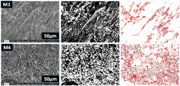
In our research, green synthesized super hydrophilic ZnO nanoparticles synthesized from waste banana peel improve the stability of the polymer membrane and act as a good stabilizing agent. Also, activated carbon helps to create maximum porosity and higher adsorption capacity and is non-toxic. So, it was blended to make a nanocomposite, which was incorporated into the polyether sulfone (PSF) and polyurethane (PU) polymer nanocomposite membrane. From the combination of the PSF/PU membrane as M1, the ACs@PSF/PU membrane as M2, and ZnO@PSF/PU membrane as M3, the ACs/ZnO@PSF/PU membrane as M4 was fabricated via a phase inversion technique. However, it is clear that the number of modifications in the polyether sulfone membrane substrates properties during the addition of nanocomposite would improve the membrane performance for water vapor permeance and selectivity. Further, PSF/PU can improve surface hydrophilicity and also increase the rate at which impurities are removed. ACs/ZnO nanocomposites can improve the anti-contaminant capacities of the polymer membrane. The major goal of this work is to examine the dye degradation utilizing M1 (plain) and M4 (modified) membranes and evaluate their potential for dye removal from an aqueous solution. The XRD pattern shows that the membrane material was amorphous. The composite membrane has a higher pore count and higher adsorption capacity, as show in the SEM analysis. The outcomes show that the composite membrane has higher adsorption of industrial wastewater and dyes compared with the plain membrane.
2. Materials and methods
2.1 Materials
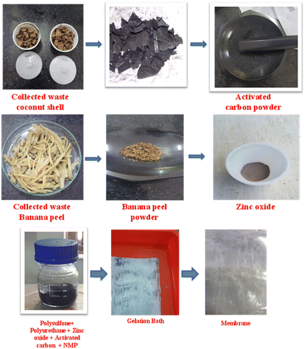
Activated carbon (among agriculture waste, coconut shells have a high carbon content and low ash content and have been suitably investigated for producing activated carbon), banana peel (the biological synthesis of nanoparticles using banana peel has received more attention due to its simplicity, low cost, nanotoxicity and environmentally friendly nature), and polyurethane (MW 312.32) were purchased from Mysore Acetate and Chemicals Company Limited. Polysulfone (high molecular weight) extra pure 800 mPa s, 90% DA) was purchased from Sisco research laboratories Pvt. Ltd and sodium hydroxide (molecular weight 39.997 g mol−1) was supplied by Sigma Aldrich. N-Methyl-2-pyrrolidone (NMP) and sodium lauryl sulfate (SLS) (molecular weight 288.38) were purchased from SRL chemicals, Chennai, India. The chemicals used in the study are analytical reagent grade and were used as received without further purification.2.2 Fabrication of mixed matrix membranes
2.3 Characterization techniques
The diffraction pattern and crystallographic structure of the synthesized material were determined using a diffractometer with Cu K radiation and powder X-ray diffraction (XRD). The functional groups were confirmed using a PerkinElmer Alpha-E FT-IR spectrometer, which has a range of 400 to 4000 cm−1. Spectroscopic and microscopic studies were used to examine the membrane's structural composition, morphological alterations, and the inner structure of the membrane. The synthesized nanoparticles' SAED pattern, morphology analysis, and elemental mapping were performed through JEOL Japan-2100 plus (HRTEM). The morphological variations of the membrane and pore structure were studied using a FEI Quanta-4700 model scanning electron microscope. The membrane's hydrophilicity was studied using the DMs-401's Kyowa water contact angle analyzer (Japan). The absorption performance was measured using Analytic Jena Specord 200 Plus Ultraviolet-visible spectrophotometry. | (1) |
The same method was used to evaluate the membrane's length swelling ratio. The membrane area that had been premeasured (Ldry, cm2) was soaked in deionized water for 48 hours at room temperature before being collected (Lwet, cm2). The following equation was used to obtain the membrane swelling ratios.
 | (2) |
2.4 Dye removal experiment
This research examines the polymer nanocomposite membrane for its dye removal capacity. To measure the efficiency of the dye degradation of the prepared membrane using Congo red and methylene blue dye, 50 mg L−1 of dye stock solution is prepared for the adsorption studies. The prepared polymer nanocomposite membrane was cut into 3 × 3 cm (which is approximately 50 mg in mass) and placed into the beaker containing 100 ml of the prepared dye sample. At 20 min intervals, 5 ml of the sample was collected for analysis. The absorbance was measured by the UV-visible spectrometer and recorded.3. Results and discussion
3.1 FTIR analysis
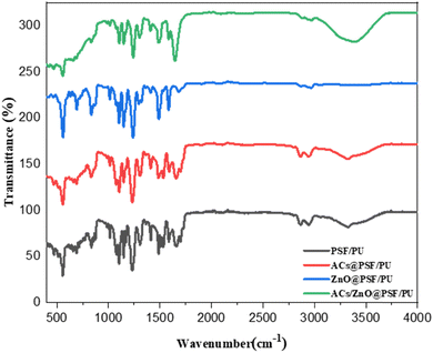
Functional group analysis of ZnO powder was performed with Fourier transmission infrared (FTIR) spectroscopy. The range of absorption peaks from 600 may prove more precise, the OH stretching mode of the hydroxyl group is assigned to a wide range at 3500 cm−1. The CH stretching vibration of the alkane groups causes the peaks to lie down between 2830 and 3000 cm−1. The ATR FTIR spectrum of the film is given in Fig. 2. The peaks observed for polysulfone film at 1151 cm−1 (OSO dilatation), 1244 cm−1 (COC dilatation) and 1585 cm−1 (aromatic CC region) are characteristic of the sulphone. In addition, absorptions at 1020 cm−1 and 830 cm−1 are related to the CH stretching of the polysulfone. These peaks show C![[double bond, length as m-dash]](https://www.rsc.org/images/entities/char_e001.gif) O and C
O and C![[double bond, length as m-dash]](https://www.rsc.org/images/entities/char_e001.gif) N bonds. A new peak appearing at 1090 cm−1 corresponds to the stretching band of NH3. On the other hand, the ester carbonyl stretching (O
N bonds. A new peak appearing at 1090 cm−1 corresponds to the stretching band of NH3. On the other hand, the ester carbonyl stretching (O![[double bond, length as m-dash]](https://www.rsc.org/images/entities/char_e001.gif) C–O) height at 1720 cm−1 is due to hydrolysis. The urethane and ester linkage breakage is supported by disappearance of the ester peak at 1170 cm−1. The bands at 1632 cm−1 and 1540 cm−1 show the presence of the amide carbonyl stretching vibration (O
C–O) height at 1720 cm−1 is due to hydrolysis. The urethane and ester linkage breakage is supported by disappearance of the ester peak at 1170 cm−1. The bands at 1632 cm−1 and 1540 cm−1 show the presence of the amide carbonyl stretching vibration (O![[double bond, length as m-dash]](https://www.rsc.org/images/entities/char_e001.gif) C–NH).19
C–NH).19
3.2 XRD analysis
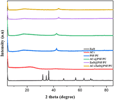
Polysulfone exhibited a broad peak at around 17.98° which indicates an amorphous structure. The same peak representing the amorphous nature of polyurethane is shown in Fig. 3. The blended PSF/PU polymer membrane exhibits a highly amorphous structure. The charcoal blended PSF/PU membrane does not show any significant change in the polymer nature. Thus, the peak at 17.98° for charcoal blended PSF/PU membrane retained its amorphous structure. The prepared zinc oxide nanoparticles show sharp peaks at 31°, 35°, 38°, 49°, 59°, 63° and 70°.20 Thus, the zinc oxide incorporated PSF/PU membrane shows similar peaks to zinc oxide at 35°, 38° and 49° as well as 17.98°, which represents the amorphous nature of the host polymer membrane and the crystalline nature of the incorporated nanofillers.3.3 SEM analysis
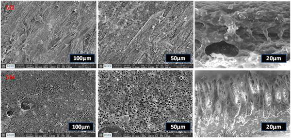
The SEM images represent the top surface and the cross-sectional images of the prepared membrane. The M1 plain PSF/PU membrane has hard, rough and mounted valleys on its surface with a lower number of pores present on the membrane surface and the cross-sectional image also represents the irregular void shape on the M1 membrane, as shown in Fig. 4. Additionally, the M4 membrane pores exhibit a regular round shape and there are honeycomb shaped pores on the surface of the membrane because of the presence of activated carbon as a pore creator material@ZnO from banana peel as a reducing and stabilising agent. The cross-sectional images of the prepared M1 membrane show that it has irregular pores and a lower number of pores, which result in less adsorption of dye molecules. The modified membrane M4 has visible pores with a round shape due to the presence of the added nanofillers. The added nanofillers are a source of pore creators and can also help to increase the adsorption capacity and thermal stability of the membrane. As a result, the membrane pattern and pore construction through the nanocomposites improve the adsorption capacity of the membrane.21| Membrane | Mean area (μm2) | Minimum area (μm2) | Maximum area (μm2) |
|---|---|---|---|
| PSF/PU [M1] | 48.57 | 0.006 | 97.134 |
| ACs/ZnO@PSF/PU [M2] | 1085.159 | 0.174 | 2170.144 |
| PSF/PU (cross sectional) [M3] | 5.049 | 0.003 | 10.096 |
| ACs/ZnO@PSF/PU (cross sectional) [M4] | 124.817 | 0.019 | 249.615 |
3.4 TEM analysis
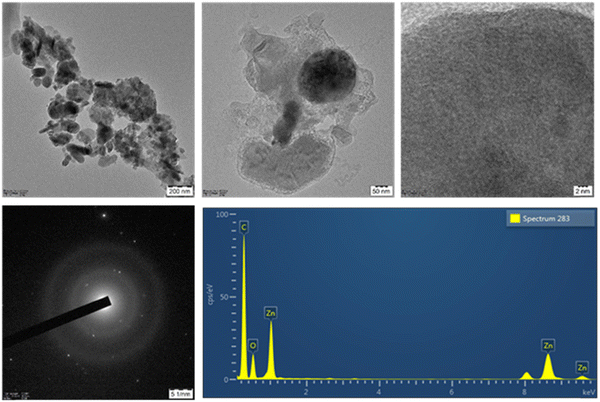
The morphology of the synthesised ACs/ZnO nanocomposite was investigated using HRTEM analysis. The particle size of ACs/ZnO is shown in Fig. 6. This indicates the formation of a uniform distribution of activated carbon nanoparticles with an average diameter of 11.55 nm and a ZnO average diameter of 78.59 nm. ZnO nanoparticles have visible lattice fringes with a spring spacing of 0.20 nm corresponding to the (1 0 3) crystallographic plane, while activated carbon has visible lattice fringes as well. The rings (1 0 4), (1 1 0), and (1 1 3) on the other hand, go well with the ZnO in the SAED design. The elemental mapping of ACs/ZnO reported the presence of Zn, C, O elements. This also denotes that the nanocomposite's structure is substantially polycrystalline.23 Lattice fringes of both the nanocomposite and a single crystal of ZnO and activated carbon nanoparticles were seen in a HRTEM image of a single crystal of ZnO and activated carbon nanoparticles.3.5 Hydrophilicity analysis
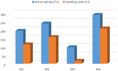
As per previous research, the PU contact angle is larger than 100°. The contact angle measurements of polymer nanocomposite membranes M4 and plain polymer M1 membranes are shown in Fig. 7. The contact angle values of the M1 membranes were found to be in the range of 69.14° resulting in the membrane material being hydrophilic in nature. On the other hand, the modified M4 membrane displayed a value of 64.74°, resulting in the membrane being able to reduce the hydrophilic valve. Consequently, the greater valve is attributed to the lower contact angle valve. The water absorption capacity of the M4 membrane has a lower absorption valve when compared with the pristine membrane. So, the hydrophilicity decreases when the addition of ACs/ZnO onto the polymer membrane results in higher absorption of water into the membrane.24 Consequently, the membrane's interactions with applications and degradation characteristics have been enhanced.There is greater water uptake as well as a higher swelling ratio of the M4 membrane after the incorporation of hydrophilic additives like the ACs/ZnO nanocomposite material, as shown in Fig. 8. Due to the presence of the pore creator ACs/ZnO, which causes thermodynamic instability in the casting solution and increases the material's hydrophilic nature, the measurement of water uptake and swelling ratio of the plain PSF/PU (M1) membrane has been shifted to the modified PSF/PU@ACs/ZnO membrane.25 Additionally, the uptake percentage contributes to the swelling ratio by increasing the amount of the hydrophilic polymer. The results show that the modified membrane is more hydrophilic in nature. So, the modified membrane has a higher absorption capacity compared with the plain membrane.
3.6 TGA analysis
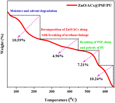
From the thermograph in Fig. 9, the initial degradation starts at the temperature of 100–210 °C with a mass loss of 10.59%, which is due to the decomposition of moisture and the solvents present in the modified PSF/PU@activated carbon/ZnO membrane. The second degradation state is visible at the temperature from 234–450 °C with a mass loss of 4.96%, which can be segregated into two decomposition stages from 234–280 °C and 300–350 °C. This is visible in the graph as a very short bend. The degradation at 234–280 °C is due to breaking of ZnO and the initial decomposition of activated carbons. The decomposition of 300–350 °C is due to the splitting of the urethane linkage of the modified membrane. The final degradation stage from 450–560 °C with weight loss of 10.24% is due to the degradation of the polysulfone chain and polyols of the polyurethane. Furthermore, the residual char is about 10.24% due to the organic and inorganic portions present on the modified PSF/PU@activated carbon/ZnO membrane. Thus, the prepared membrane could be a stable material for water treatment.4. Adsorption studies
Fig. 10 shows the ability of the activated carbon/ZnO@PSF/PU and the plain membrane in adsorbing methylene blue and Congo red dye. From the graphical representation it is clear that the plain polymer membrane has a lower adsorption capacity, whereas the adsorption of methylene blue and Congo red was visibly increased from the UV-Vis analysis for activated carbon/ZnO@PSF/PU. The increase in the adsorption of dye molecules on activated carbon/ZnO@PSF/PU is due to some of the basic interaction driving forces such as hydrogen bonding, electrostatic interaction, complexation and dispersion forces.26 The polyols, sulfonyl, ether groups and zinc oxide presence help in attracting the cationic and anionic dyes. The increased hydrophilic nature of the activated carbon/ZnO@PSF/PU can help in the uptake of water molecules through the increased pore size, which eventually helped in creating active sites that bind the methylene blue and Congo red dye molecules via incorporation of activated carbon/ZnO. Furthermore, the electrons of C![[double bond, length as m-dash]](https://www.rsc.org/images/entities/char_e001.gif) C and N
C and N![[double bond, length as m-dash]](https://www.rsc.org/images/entities/char_e001.gif) N of methylene blue and Congo red can attach with the pi electrons dispersed on the membrane surface. The highest adsorption on activated carbon/ZnO@PSF/PU was 97% at 100 min due to the well-known mechanism of non-covalent interaction, π–π stacking and electrostatic attraction between the aromatic species present in the backbone of the dye molecules occupying the vacant active site present in the membrane surface.27–29
N of methylene blue and Congo red can attach with the pi electrons dispersed on the membrane surface. The highest adsorption on activated carbon/ZnO@PSF/PU was 97% at 100 min due to the well-known mechanism of non-covalent interaction, π–π stacking and electrostatic attraction between the aromatic species present in the backbone of the dye molecules occupying the vacant active site present in the membrane surface.27–29
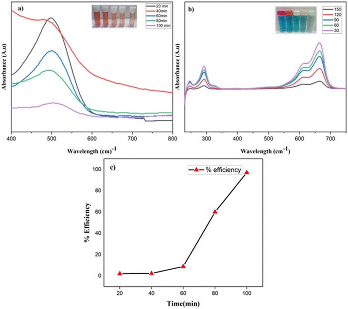 | ||
| Fig. 10 UV-analysis of dye removal of (a) Congo red and (b) methylene blue by the prepared membrane and dye removal efficiency. (c) % efficiency of dye removal of the M4 membrane. | ||
4.1 Adsorption isotherm
The sorption mechanism was examined using the Langmuir and Freundlich isotherm models. The linear equations of Langmuir and Freundlich isotherm is described as follows,The Langmuir isotherm is expressed as
 | (3) |
The Freundlich isotherm is expressed as
 | (4) |
The results in the experimental valves predicted from the Langmuir isotherm model were predicted with R2 = 0.9072 compared with the Freundlich isotherm model R2 = 0.8117 based on the linear fit value of the adsorption isotherm, as shown in Fig. 11(a and b). The adsorption on binding sites and the membrane mechanism involved the dye particles on active sites in the porous membrane area. As a result, the Langmuir isotherm is the greatest fit for the adsorption mechanism for the prepared membrane and the dye particles. However, the major challenges of maintaining the ACs/ZnO nanocomposite loading ratios in the membrane and the leaching out of the nanoparticles in the ZnO/ACs@PSF/PU polymer nanocomposite membrane are to be noted. Therefore, it is essential to check the leaching level of the prepared membrane. In this study, the chemisorptive monolayer adsorption with a limited number of identical sites was used to adsorb the Congo red and methylene blue dyes on a homogeneous surface.
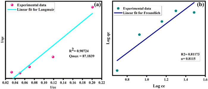 | ||
| Fig. 11 (a) Langmuir adsorption isotherm of the ACs/ZnO@PSF/PU membrane and (b) the Freundlich adsorption isotherm of the ACs/ZnO@PSF/PU membrane. | ||
4.2 Analysis of Zn leaching
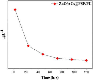
The Zn leaching from the ACs/ZnO@PSF/PU membrane was analyzed by the immersion technique. The leaching samples were analyzed by ICP-MS and the results are plotted as shown in Fig. 12. The ZnO nanoparticles are well conjugated within the surface of the PSF/PU membrane. According to the graph, the release of zinc from the membrane was steady and slow. The result shows that the material has released about 70–90% of the zinc within 3–5 days. There was the highest release of zinc after 48 h. As per the norms of WHO, domestic water should consist of 5 ppm L−1. Though the leached amount of zinc is greater than the limit, the leaching is in a non-hazardous zone.32,33 The antibacterial and anti-inflammatory properties of the membrane depend on the Zn release from the membrane. The membrane has a slow and steady release of Zn which is correlated with the attachment of Zn through the amine group in the PSF and polyols in polyurethanes. Hence this approach can release Zn at a steady rate which results in the prolonged life of the membrane.34,355. Final remarks
This work reports the dye removal efficiency of a polymer nanocomposite membrane in polluted water treatment. This remark explains the merits and demerits of the prepared polymeric membrane, synthesised methods, and removal efficiency. The merits of the as-prepared membrane is followed by the Phase Inversion Method which is a demixing technique where a homogeneous polymer solution is converted into liquid phase into solid phase in a controlled manner. The concentration of the polymer is high, the membrane valves and porosity are low. The merits of the phase inversion method are a simple technique, high reproducibility, low tendency to create defects, and controlled porosity, the fixed temperature maintained in the gelation bath also increases the membrane purity and pore count. From the previous reports in the literature, Valeen et al. reported that the polysulfone-sulfated nano-titania (S-TiO2) nanofiltration membrane achieves 90.4% of methylene blue dye rejection at 10 ppm under UV radiation. Although Mokhtar et al. reported that the PVDF-Cloisite hollow fibre composite membrane for treatment of effluent containing dyes and salts using membrane distillation work results in 97% of rejection.36 The present work shows that activated carbon/ZnO@PSF/PU was 97% at 100 min due to the well-known mechanism of non-covalent interaction. On the other hand, the demerit for membrane preparation is non-uniform thickness in the membrane area. During aeration of the polymer gel, the nanoparticles settled at the bottom of the flask. From the authors’ point of view, the polymer selection for preparing membranes as eco-friendly and stable biopolymers can increase the time for longterm use of membranes. The prepared polymer nanocomposite membrane achieves 97% of removal in 100 min. So, the prepared membrane in higher scale production is effective for dye removal in wastewater. Additionally, the adsorption batch experiment was performed by leaching of Zn nanoparticles. The adsorption isotherm was clearly fitted with Langmuir by R2 = 0.9072 and Freundlich by R2 = 0.8117, which represents the presence of active sites. As a result, the synthesized membrane could be a great source of dye adsorption material in an economical manner and in future large-scale applications by making a few more improvements.6. Conclusions
The achievement of this work is that we used a simple eco-friendly readily-available (coconut shell and banana peel) green synthesis of nanocomposites. This research revealed a novel approach to develop biodegradable polymers for high-efficiency dye removal. The suitable and rational selection of raw materials for the membrane is critical to the success of this work. It is possible to prepare the membrane at low cost. The XRD pattern showed the amorphous nature. SEM analysis shows more pores in the composite membrane so it has excellent absorption capacities. There are strong electrostatic interactions between the activated carbon@ZnO nanocomposites and PSF/PU polymer, the conjugated dye molecules may bind to expansive aromatic domains in polymer composite membranes, thereby increasing reactivity. As a result, the AC/ZnO@PSF/PU membrane will be a useful adsorbent for applications involving dye removal.Conflicts of interest
There are no conflicts to declare.References
- A. Wutich, A. Y. Rosinger, J. Stoler, W. Jepson and A. Brewis, Am. J. Hum. Biol., 2019, 32, e23350 Search PubMed.
- F. S. Alhamlan, A. A. Al-Qahtani and M. N. Al-Ahdal, J. Infect. Dev. Countries, 2015, 9, 128–135 CrossRef PubMed.
- S. Sultana, N. Ahmad, S. M. Faisal, M. Owais and S. Sabir, IET Nanobiotechnol., 2017, 11, 835–842 CrossRef.
- S. Sultana, N. Ahmad, S. M. Faisal, M. Owais and S. Sabir, IET Nanobiotechnol., 2017, 11, 835–842 CrossRef.
- S. Phuntsho, S. Hong, M. Elimelech and H. K. Shon, J. Membr. Sci., 2013, 436, 1 CrossRef CAS.
- F. C. Wu, R. L. Tseng and R. S. Juang, Chem. Eng. J., 2009, 153, 1 CrossRef CAS.
- Q. Ping, Z. Huang, C. Dosoretz and Z. He, Water Res., 2015, 77, 13 CrossRef CAS PubMed.
- T. Yang, J. Peng, Y. Zheng, X. He, Y. Hou, L. Wu and X. Fu, Appl. Catal., B, 2018, 221, 223–234 CrossRef CAS.
- S. Leong, A. Razmjou, K. Wang, K. Hapgood, X. Zhang and H. Wang, J. Membr. Sci., 2014, 472, 167–184 CrossRef CAS.
- Y. Yang, P. Wang and Q. Zheng, J. Polym. Sci., Part B: Polym. Phys., 2006, 44, 879–887 CrossRef.
- A. Rahimpour, M. Jahanshahi, B. Rajaeian and M. Rahimnejad, Desalination, 2011, 278, 343–353 CrossRef.
- J. D. le Roux and D. R. Paul, J. Membr. Sci., 1992, 74, 233–252 CrossRef.
- R. Singh and M. K. Purkait, J. Appl. Polym. Sci., 2017, 134, 45290 CrossRef.
- L. Jin, Y. Gao, J. Yin, X. Zhang, C. He, Q. Wei, X. Liu, F. Liang, W. Zhao and C. Zhao, J. Hazard. Mater., 2020, 400, 123203 CrossRef PubMed.
- W. Li, K. Yang, J. Peng, L. Zhang, S. Guo and H. Xia, Ind. Crops Prod., 2008, 28, 190–198 CrossRef.
- C. Song, S. Wu, M. Cheng, P. Tao, M. Shao and G. Gao, Sustainability, 2014, 6, 86–98 CrossRef.
- A. Dmochowska, J. Czajkowska, R. Jędrzejewski, W. Stawiński, P. Migdał and M. Fiedot-Toboła, Int. J. Biol. Macromol., 2020, 165, 1581–1592 CrossRef CAS.
- S. Sivasankari, R. Kalaivizhi, N. Gowriboy, M. R. Ganesh and M. Shazia Anjum, Polym. Compos., 2021, 42, 5512–5526 CrossRef CAS.
- A. Kumar and H. Gupta, Environ. Technol. Innovation, 2020, 20, 101080 CrossRef CAS.
- T. V. Surendra, S. M. Roopan, N. A. Al-Dhabi, M. V. Arasu, G. Sarkar and K. Suthindhiran, Nanoscale Res. Lett., 2016, 11, 546 CrossRef CAS.
- M. Alhoshan, J. Alam, L. A. Dass and N. Al-Homaidi, Adv. Polym. Technol., 2013, 32(4) DOI:10.1002/adv.21369.
- A. Kumar, Y. S. Negi, N. K. Bhardwaj and V. Choudhary, Carbohydr. Polym., 2012, 88, 1364–1372 CrossRef CAS.
- Y. Chen, L. Yan, T. Yuan, Q. Zhang and H. Fan, J. Appl. Polym. Sci., 2011, 119, 1532–1541 CrossRef.
- M. S. Yadav, N. Singh and A. Kumar, J. Mater. Sci.: Mater. Electron., 2018, 29, 6853–6869 CrossRef.
- H. Zhang, K. Li, C. Yao, J. Gu and X. Qin, Colloids Surf., A, 2021, 629, 127493 CrossRef.
- N. Bose, K. Rajappan, G. Natesan and S. Selvam, Int. J. Polym. Mater. Polym. Biomater., 2022 DOI:10.1080/00914037.2022.2066670.
- Y. Xu, D. Yuan, J. Bao, Y. Xie, M. He, Z. Shi, S. Chen, C. He, W. Zhao and C. Zhao, J. Mater. Chem. A, 2018, 6, 13359–13372 RSC.
- Y. Chen, Z. Xiang, D. Wang, J. Kang and H. Qi, RSC Adv., 2020, 10, 23936–23943 RSC.
- R. Zhang, Y. Liu, M. He, Y. Su, X. Zhao, M. Elimelech and Z. Jiang, Chem. Soc. Rev., 2016, 45, 5888–5924 RSC.
- F.-C. Wua, R.-L. Tsengb and R.-S. Juang, Chem. Eng. J., 2009, 153, 1–8 CrossRef.
- K. Periasamy and C. Namasivayam, Ind. Eng. Chem. Res., 1994, 33, 317–320 CrossRef CAS.
- X. Li, R. Pang, J. Li, X. Sun, J. Shen, W. Han and L. Wang, Desalination, 2013, 324, 48 CrossRef CAS.
- K. Zodrow, L. Brunet, S. Mahendra, D. Li, A. Zhang, Q. Li and P. J. J. Alvarez, Water Res., 2009, 43, 715 CrossRef CAS.
- P. G. Ingole, R. R. Pawar, I. Baig, J. D. Jeon and H. Lee, J. Mater. Chem. A, 2017, 10, 1039 Search PubMed.
- N. Nasrollahi, S. Abera, V. Vatanpour and N. M. Mahmoodi, Compos. B. Eng., 2015, 388–409 Search PubMed.
- N. M. Mokhtar, RSC Adv., 2015, 5, 38011–38020 RSC.
| This journal is © The Royal Society of Chemistry 2022 |

