 Open Access Article
Structure-engineering of core–shell ZnCo2O4@NiO composites for high-performance asymmetric supercapacitors†
Gokul P.
Kamble
a,
Akash S.
Rasal
ab,
Jia-Yaw
Chang
b,
Sanjay S.
Kolekar
c,
Shivaji N.
Tayade
 d and
Anil V.
Ghule
 *a
*a
aGreen Nanotechnology Laboratory, Department of Chemistry, Shivaji University, Kolhapur 416004, Maharashtra, India. E-mail: avg_chem@unishivaji.ac.in
bDepartment of Chemical Engineering, National Taiwan University of Science and Technology, Taipei, Taiwan
cAnalytical Chemistry and Material Science Research Laboratory, Department of Chemistry, Shivaji University, Kolhapur 416004, Maharashtra, India
dDepartment of Chemistry, Shivaji University, Kolhapur, 416004, Maharashtra, India
First published on 24th December 2021
Abstract
The implementation of a structure-designed strategy to construct hierarchical architectures of multicomponent metal oxide-based electrode materials for energy storage devices is in the limelight. Herein, we report NiO nanoflakes impregnated on ZnCo2O4 nanorod arrays as ZnCo2O4@NiO core–shell structures on a flexible stainless-steel mesh substrate, fabricated by a simple, cost-effective and environmentally friendly reflux condensation method. The core–shell structure of ZnCo2O4@NiO is used as an electrode material in a supercapacitor as it provides a high specific surface area (134.79 m2 g−1) offering high electroactive sites for a redox reaction, reduces the electron and ion diffusion path, and promotes an efficient contact between the electroactive material and electrolyte. The binder-free ZnCo2O4@NiO electrode delivers a high specific capacitance of 882 F g−1 at 4 mA cm−2 current density and exhibits remarkable cycling stability (∼85% initial capacitance retention after 5000 charge–discharge cycles at 10 mA cm−2). The asymmetric supercapacitor device ZnCo2O4@NiO//rGO delivered a maximum energy density of 46.66 W h kg−1 at a power density of 800 W kg−1. The device exhibited 90.20% capacitance retention after 4000 cycles. These results indicate that the ZnCo2O4@NiO architecture electrode is a promising functional material for energy storage devices.
1. Introduction
The increase in environmental pollution, dramatic climate change, global warming, growing energy consumption, and depletion of fossil fuels have compelled research on developing efficient energy storage systems. In recent decades, researchers have expressed tremendous interest in exploring novel energy storage devices such as fuel cells, batteries and electrochemical capacitors (supercapacitors).1,2 Among these energy storage systems, supercapacitors (SCs) are at the forefront and have received remarkable consideration in a wide range of applications such as in hybrid vehicles, pacemakers, intermittent power supply systems, and portable electronics. SCs are classified as electrochemical double-layer capacitors (EDLCs) or pseudocapacitors based on their charge-storage mechanisms. EDLCs store energy by charge diffusion by forming an electric double layer at the interface of the electrode and the electrolyte; however, they possess low energy density. On the other hand, pseudocapacitors are associated with reversible faradaic redox reactions and offer much higher energy density than EDLCs.3 The energy density varies with the electrode material, and thus, to improve the energy density, the electrode material of the supercapacitor should be rationally designed to boost the electrochemical performance of the supercapacitor. Furthermore, transition metal oxides (TMOs) with microstructure spinels of the AB2O4 type ternary transition metal oxide have been extensively researched as electrode materials for SCs.4 Spinel metal cobaltites (MCo2O4: M = Mn, Cu, Ni, Fe, Zn, etc.) as electrode materials are promising because of the presence of mixed-valence metal cations that provide supplementary active sites and contribute to an enhancement in the electrochemical activity in comparison with single-component metal oxides.5,6 Along with the electrode material, the substrate material is also a considerable factor dictating electrochemical performance. High cost and toxicity concerns are the limiting factors associated with some of the substrates, such as carbon cloth, Ni foam, and Cu and Ti foil. However, the flexible stainless-steel mesh (FSSM) substrate employed in the present work is abundant, cost-effective, possesses less toxicity and provides a rough surface for the adherent deposition of the electroactive material for binder-free deposition of the material. Among the various synthetic methods of metal oxides, the reflux condensation method is simple, cost-effective, and provides scope to tune the morphology of the deposited material by altering the reaction conditions. The electrochemical performance of the electrode material is also concerned with the rational design of the crystal structure and diverse morphologies and shapes such as cubes, spheres, prisms, tubes, sheets, hexagons, wires, fibres, disks, and rods. The strength of nanostructured electroactive materials is attributed to the cyclic stability over an extended range of charge–discharge during a redox reaction. The essential physical properties of electrode materials, like large surface area, shorter diffusion path for ions and electrons, and porosity of the material, have been implemented by a core–shell structural arrangement of nanoparticles. The core–shell arrangement consists of inner (core) and outer (shell) materials. The core material with functional properties shielded by the shell protects the core and sustains its performance for a longer period. The properties of a material can be modified by altering the core to shell ratio and/or the constituent materials. Furthermore, both the constituents become complementary to each other and provide special properties to the core–shell architecture. The porous or efficient networked arrangement of the core–shell architecture could prevent aggregation of the materials and offers more utilization of the underlying material by providing a large surface area and free access to ions and electrons through a short diffusion path.7 The internal resistance, efficiency, stability, and rate capability also depend on the synergistic effect and structural interconnectivity of the two components. The metal oxide-based core–shell constructions could impart a number of possible beneficial characteristics to the electrode material, such as (1) allow high transport rates for ions and electrons; (2) restrict volume expansion and maintain the structural integrity; (3) strengthen or bring new physical or chemical properties; (4) prevent the core from aggregating into large particles; and (5) protect the active core from outside environmental changes.8Interestingly, ZnCo2O4 has received extensive attention because of its high theoretical capacitance, excellent redox activity, high abundance, lower cost, and its environmentally benign nature. However, its low structural sustainability during redox reactions limits it from being considered as an electrode material for high-performance supercapacitors. On the other hand, NiO is proved to have high theoretical capacitance, low cost, low toxicity, and natural abundance, but its deprived cycle stability and high electrical resistance limit its use as an individual electrode material for SCs.9 Thus, the construction of such a hierarchical architecture involving combined nanostructures of ZnCo2O4 and NiO is expected to possess high electrochemical performance as a heterostructured architecture and can provide advantages of both components offering special properties through strengthening or altering each other.10 With this motivation, it was expected that the fabrication of core/shell nanostructured arrays could exhibit fascinating properties by taking advantage of the synergistic effect of the heterostructures.
In the present work, we report a cost-effective and simple strategy for the direct growth of a hierarchical ZnCo2O4@NiO composite, where the ZnCo2O4 nanorods are grown on the current collector, with NiO nanoflakes emerging through the ZnCo2O4 nanorods. This novel hierarchical electrode offers several advantages. Firstly, the long ZnCo2O4 nanowires serve as both the backbone and conductive path for the NiO nanoflakes. The vertically aligned nanoflakes of NiO result in increased surface area providing more active materials per unit area. Secondly, the NiO nanoflakes expand the interface area with electrolytes and protect the inner ZnCo2O4 backbone from deterioration during the electrochemical performance, which improves the durability of the material. Next, it provides a good mechanical bond and electrical connection with the current collector. Lastly, the meso–macroporous NiO nanoflakes significantly enhance the surface for electrode–electrolyte contact and ion diffusion, which is significant to achieving high-power energy storage.11 Due to these unique advantages of a self-supporting core–shell architecture, the resulting hierarchical ZnCo2O4@NiO composite binder- and additive-free supercapacitor exhibits higher capacity, enhanced rate capability, and improved cycling stability as compared to pristine ZnCo2O4 and NiO.
2. Experimental
2.1. Preparation of ZnCo2O4 (ZCO) architecture on the FSSM
All the reagents were of analytical grade and were used without further purification. Before the deposition, the substrate FSSM was washed ultrasonically with soap solution, distilled water, and ethanol individually for 15 minutes. In a typical synthesis, 20 mL each of 0.05 M ZnCl2·6H2O (zinc chloride), 0.1 M CoCl2·6H2O (cobalt chloride), 0.2 M NH4F (ammonium fluoride), 0.6 M NH2CONH2 (urea) and C2H5OH (ethanol) were refluxed at 120 °C in a round-bottom flask containing vertically fixed FSSM (1 × 1 cm) for 12 h. The thin film deposited on FSSM was washed with ethanol and deionized water to remove loosely bonded particles. Finally, the film was annealed at 400 °C in an air muffle furnace for 2 h.2.2. Preparation of ZnCo2O4@NiO
50 mL solution of 0.5, 1, and 2 mmol NiSO4·6H2O with 20 mmol urea in deionized water were refluxed at 95 °C for 8 h in a round-bottom flask in which ZCO on FSSM was vertically fitted. After natural cooling, the as-prepared sample was washed repeatedly with deionized water and ethanol, and then annealed at 350 °C for 2 h in the presence of air. The samples were named NZ-0.5, NZ-1, and NZ-2 for 0.5, 1, and 2 mmol NiSO4·6H2O, respectively.2.3. Fabrication of the flexible ASC device
NZ-1/FSSM as the positive electrode and reduced graphene oxide rGO/SSM as the negative electrode were used to assemble the ASC device with filter paper (separator) sandwiched between the two electrodes. The assembly was further soaked in PVA-KOH gel electrolyte and kept for natural drying for 3 h. The PVA-KOH gel electrolyte was constituted by dissolving 5 g PVA and 4 g KOH in 80 mL distilled water under stirring at a constant temperature maintained at 90 °C. The mass of active material deposited on the substrates (NZ-1/FSSM; 2.5 mg and rGO/FSSM; 2.5 mg) was calculated using the weight difference method.2.4. Material characterization
X-ray diffraction (XRD) studies were performed (Bruker, D8-Phaser X-ray diffractometer) with Cu Kα1 (1.5406 Å) radiation in the range of 10–80°. Thermogravimetric analysis (TGA) was carried out in the temperature range of 50–800 °C at 20 °C min−1 in an air atmosphere. KBr pellet containing a trace amount of powder sample was used to record the Fourier transform infrared (FTIR) spectra (Bruker Alfa Spectrometer) in the range of 480 to 4000 cm−1. The structural morphology of ZnCo2O4@NiO was obtained by scanning electron microscopy (SEM, Mira3, TESCAN) and transmission electron microscopy (TEM, PHILIPS, CM 200, USA). The EDS and elemental mappings were recorded on a JEM-2100F system (JEOL). X-ray photoelectron spectroscopy (XPS) analysis was carried out (VG Multilab ESCA, USA) with a Mg Kα source (1.254 keV). The surface area and pore size distributions of ZnCo2O4@NiO were evaluated by the Brunauer Emmett Teller (BET) method (NOVA1000e Quantachrome, USA).2.5. Electrochemical measurements
All electrochemical measurements were carried out under ambient conditions using an electrochemical workstation (PGSTAT302N potentiostat, Metrohm Autolab). The three-electrode device was constructed with the as-prepared electroactive materials on FSSM, an Ag/AgCl electrode, and a graphite electrode acting as the working electrode, reference electrode, and counter electrode, respectively, in a 6 M KOH solution as the electrolyte. Specific capacitances (Csp, F g−1), energy density (E, W h kg−1), and power density (P, kW kg−1) were calculated from the following equations:| Csp = (I × Δt)/(m × ΔV) | (1) |
| E = Csp × (ΔV)2/7.2 | (2) |
| P = (3.6 × E)/Δt | (3) |
3. Results and discussion
The ZnCo2O4@NiO nanostructure was fabricated on conductive flexible stainless-steel mesh (FSSM) substrates through a two-step process. Firstly, Zn–Co precursor nanorods (NRs) were grown on the FSSM by the reflux condensation reaction method (RCM) followed by thermal annealing treatment to convert the Zn–Co precursor into ZCO NRs. Secondly, NiO nanoflakes (NFs) were grown on the ZCO NRs by RCM followed by thermal annealing treatment.XRD analysis was employed to identify the crystal structure and phase composition information of both ZnCo2O4@NiO and the pristine NiO samples (Fig. 1(a)). The primary diffraction peaks at 2θ = 18.68°, 30.88°, 36.34°, 43.74°, 58.78°, and 64.57° correspond to the lattice planes of (1 1 1), (2 2 0), (3 1 1), (4 0 0), (5 1 1) and (4 4 0) of ZCO. The diffraction peaks at 2θ = 36.76°, 43.10°, and 62.54° correspond to the reflection planes of (1 1 1), (2 0 0), and (2 2 0) of NiO. All the peaks accordingly indicate cubic ZCO with a spinel structure (JCPDS no. 23-1390) and a face-centred cubic structure phase NiO (JCPDS no. 36-1451). The results confirm the coexistence of the ZCO and NiO phases after the deposition process without any impurities and contaminants. The peak intensities of NZ-0.5, NZ-1, and NZ-2 are quite similar and indicate that there is no remarkable alteration in the crystallinity of NiO.12
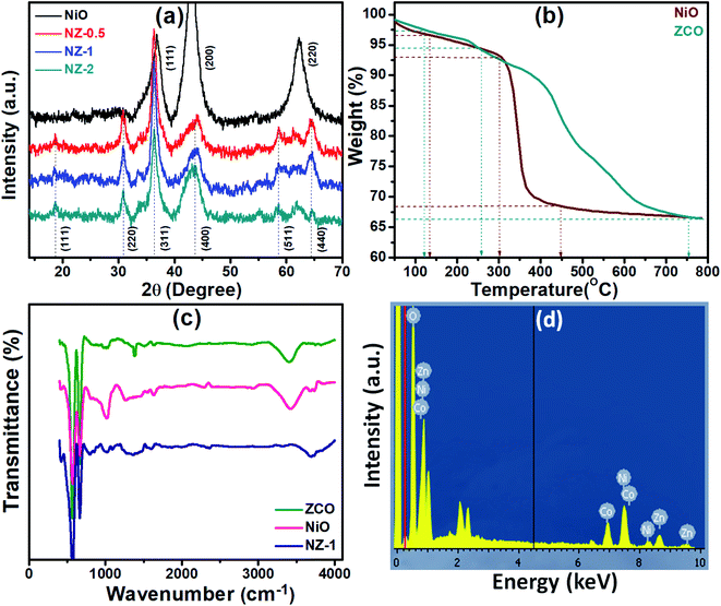 | ||
| Fig. 1 Representative (a) XRD spectra of NiO, NZ-0.5, NZ-1, and NZ-2; (b) TGA thermograms of ZCO and NiO; (c) FTIR spectra of ZCO, NiO, and NZ-1 precursors; and (d) EDS spectrum of NZ-1. | ||
The TGA thermograms of the as-prepared ZCO and NiO are presented in Fig. 1(b). The experiment was carried out in an air atmosphere at a heating rate of 20 °C min−1 in the temperature range of 50–800 °C. The initial 2% weight loss for ZCO and 3% weight loss for NiO at about 100 °C account for the loss of surface adsorbed moisture. In the second step, weight loss of about 3% occurs between 100 °C to 300 °C and is attributed to the decomposition of the surface adsorbed organic residues and contaminants. The third step of weight loss (∼28%) in the temperature range of 300 to 700 °C for ZCO and the sharp weight loss of ∼26% from 300 °C to 450 °C for NiO can be attributed to the decomposition of carbonaceous materials and the subsequent oxidation of the same.13,14 The TGA analysis was useful in determining the annealing temperature and ensuring the decomposition of metal salts and the organic complex-forming pure and stable metal oxides. FTIR spectra of ZCO, NiO and NZ-1 (Fig. 1(c)) were recorded to confirm the spinel structure of the metal oxide. The spinel-type oxide exhibits two bands in the wavenumber range of 400–700 cm−1. The prepared samples validate the formation of the spinel structure as they contain two absorption peaks at 640–670 and 560–580 cm−1 corresponding to the M–O vibration frequency of the metal at the tetrahedral and octahedral clearance, respectively. The prominent band of the CO32− ions was observed at 1629–1633 cm−1. A broad peak at around 3200–3600 cm−1 is attributed to chemisorbed water.15 The elemental chemical composition for Ni, Zn, Co, and O elements of NZ-1 was studied by EDS, as shown in Fig. 1(d).
The morphology and structures of the hierarchical 3D ZnCo2O4@NiO nanocomposites were mainly characterized through SEM and TEM. Fig. 2(a) (ZCO) depicts the SEM images of the pure ZCO NRs with a length of 3–4 μm and a width of ∼1 μm covering all over the FSSM substrate. The inset shows a magnified image of pure ZCO NRs. This unique morphology of ZCO is favourable for electrolyte access and electron transportation. The effect of concentration of the NiO precursor solution during RCM on the growth of NiO NFs and ultimately on the electrochemical performance of the composite was studied systematically.16 The SEM images of NZ-0.5, NZ-1, and NZ-2 shown in Fig. 2(b–d) are of the composites prepared using the NiO precursor concentrations of 0.5 mmol, 1 mmol, and 2 mmol, respectively. Fig. 2(b) (NZ-0.5) shows the limited growth of NiO NFs on the surface of ZCO NRs, whereas, the SEM image shown in Fig. 2(c) (NZ-1) depicts the interconnected and intersected NFs of NiO enabling appreciable access to electrons and electrolyte ions. The NiO NFs provide mechanical strength to the structure as they show very uniform, thin, and rupture free growth protecting the underlying NRs, thereby improving their sustainability during the redox reaction. No peeling or ruptures were observed at the intersection of the NRs and NFs, indicating the excellent mechanical bond between the ZCO NRs and NiO NFs. Eventually, the NiO NFs seem to have emerged through the NRs, which can serve as an anchor for the NFs and not allow them to detach from the NRs. In addition, the hydroxyl groups of the ZnCo precursors are more likely to bind to the hydroxyl groups in Ni(OH)2, which directs the preferable growth of Ni(OH)2 on the ZCO NRs.17 The NiO NFs are vertically aligned and separated from each other, producing cavities between them. This permits partial exposure of ZCO NRs to the electrolyte, which elevates the surface area and creates channels for electron/ion transportation. The advantages imparted to the core material by constructing a shell on it improve the electrochemical performance of the nanostructure. The concentration of the Ni precursor is one of the important parameters because when the concentration of the Ni precursor was raised to 2 mmol during the preparation, a somewhat distorted growth of the NFs was observed, as shown in Fig. 2(d) (NZ-2). The random growth of NiO NFs is observed due to the agglomeration of particles. The agglomeration leads to loss of bonding between the core and the shell, which eventually gets disintegrated easily during the redox reaction by exposing the core material, which results in lowering the withstanding capacity of the material for long charge–discharge cycle stability.
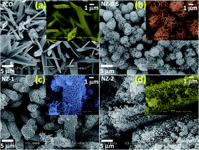 | ||
| Fig. 2 SEM images of (a) ZCO, (b) NZ-0.5, (c) NZ-1 and (d) NZ-2 and the insets are the corresponding high magnification SEM images. | ||
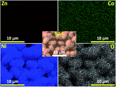
The TEM image of NZ-1 reveals that the composite comprises nanoparticles with a grain size of 40–50 nm with numerous pores in the mesoporous range (Fig. S1†). The pores generated all over the surface of the composite material are due to the combustion of the residual carbonaceous material impregnated during the synthesis process that further evolved into carbon dioxide during thermal annealing. The pores offer an excellent conductive connection between the ZCO NRs and NiO NFs and accelerate the redox reaction process, thereby reducing the path for ion diffusion and electron transfer. Furthermore, the EDS elemental mapping (Fig. 3) of NZ-1 depicts the uniform distribution of the constituents of the composite all over the architecture and the successful deposition of NiO NFs on the ZCO NRs, which is favourable to the charge accumulation during a redox reaction.
X-ray photoelectron spectroscopy (XPS) was used to determine the chemical composition and oxidation states of the ZnCo2O4@NiO (NZ-1) composite, as shown in Fig. 4. The survey spectrum (Fig. S2†) reveals the presence of Zn, Co, Ni, and O elements indicating the successful formation of the material without any impurities. The high-resolution XPS spectrum of Ni 2p shown in Fig. 4(a) exhibits two peaks at 856.9 and 875.4 eV corresponding to Ni 2p2/3 and Ni 2p1/2, respectively, along with two shakeup satellite peaks indicating its multiple oxidation states.18,19 The peaks at the binding energies of 856.2 and 873.8 eV are ascribed to Ni2+, whereas the peaks at 857.6 and 876.1 eV are ascribed to Ni3+.6Fig. 4(b) shows the Co 2p emission spectrum with two peaks at the binding energies of around 796.0 and 779.1 eV, which correspond to Co 2p1/2 and Co 2p3/2 accompanied by two satellite peaks (represented as ‘Sat.’). The deconvoluted peaks at the binding energies of 779.2 and 795.5 eV are assigned to Co3+, while the peaks at 780.9 and 796.8 eV are assigned to Co2+.20,21 The Zn 2p spectrum (Fig. 4(c)) indicates that the two main peaks correspond to the binding energies at 1046.6 and 1023.5 eV are ascribed to Zn 2p1/2 and Zn 2p3/2. The spectrum does not have any satellite peaks, indicating that Zn does not exist with multiple oxidation states. The O 1s spectrum of NZ-1 is divided into two components, marked as O1 and O2 (Fig. 4(d)). The O1 peak at 530.0 eV is due to the lattice oxygen of the metal–oxygen bonds. The O2 peak at 531.2 eV corresponds to the adsorbed water.22
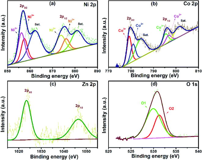 | ||
| Fig. 4 Representative XPS spectra obtained from NZ-1. (a–d) High-resolution XPS spectra for Ni, Co, Zn and O. | ||
The N2 adsorption/desorption technique was utilized to examine the microstructure of the ZnCo2O4@NiO composite. All materials exhibit a typical type-IV isotherm with an H3 hysteresis loop opening in the relative pressure range of 0.3–1.0 (P/Po) indicating the mesoporous nature of the material, according to the IUPAC system (Fig. 5).23 The porosity of the material is one of the important parameters, as it improves the electrolyte ion/electron access; thus, the composite material was characterized by the Brunauer–Emmett–Teller (BET) and Barrett–Joyner–Halenda (BJH) pore size distribution methods to evaluate the specific surface area (SSA) and pore radius. The SSA of pristine ZCO (87.60 m2 g−1),24 as well as of NiO (100.47 m2 g−1), are comparatively less than that of the composite, indicating the presence of ZCO and NiO together in the core–shell, contributing to the complementary increase in SSA. The distribution and alignment of NiO NFs over the surface of ZCO NRs are essential for the adsorption of N2 gas. The NZ-1 composite material exhibits higher SSA (134.79 m2 g−1) than NZ-0.5 (122.56 m2 g−1) and NZ-2 (121.80 m2 g−1), and these results are correlated with the observed morphological changes of the samples. The average pore diameter of the pristine and composite material was observed to be ∼2 nm (1.83 nm for NZ-0.5 and NZ-1), indicating the mesoporous nature, and is sufficient for providing easy access to the aq. KOH electrolyte ions possessing ionic radii <0.3 nm to reach the underlying electrode surfaces by providing more channels and shortening the distance of ion/electron transport of the material (insets of Fig. 5).25 The large SSA of ZnCo2O4@NiO (NZ-1) is expected to provide more electrochemical active sites, thereby improving the charge storage capability.26–28
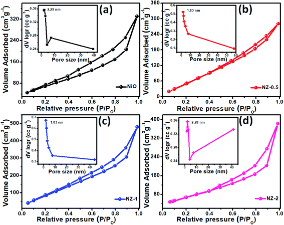 | ||
| Fig. 5 Nitrogen adsorption–desorption isotherms of (a) NiO, (b) NZ-0.5, (c) NZ-1, and (d) NZ-2 and their respective pore size distribution curves as insets. | ||
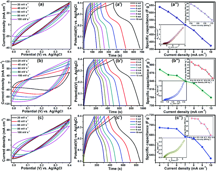
ZnCo2O4@NiO/FSSM was directly used as an electrode for SCs. Fig. 6(a) displays the cyclic voltammetry (CV) curves of the composite electrode at the scan rates of 20, 40, 60, 80, and 100 mV s−1 within a potential window of 0 to 0.4 V in 6 M KOH aqueous solution. The CV curve of ZCO prepared by the reflux condensation at 120 °C is shown in Fig. S3,† which reveals a pair of redox peaks at 0.17 and 0.36 V, which could be attributed to the faradaic redox reaction/pseudo-capacitive behaviour of ZCO. The electrochemical performance of NiO in terms of CV, GCD, and EIS is shown in Fig. S4,† which exhibit 285 F g−1 specific capacitance at 1 mA cm−2 current density. The CV curves of NZ-0.5, NZ-1, and NZ-2 are shown in Fig. 6(a), (b), and (c), respectively, indicating that the pair of redox peaks becomes unapparent due to the synergistic effect of NiO with ZCO, and the absence of redox peaks specifies that a charge–discharge process occurs at a constant rate over the entire potential window.29,30 The area under the CV curve of NZ-1 is larger than those of NZ-0.5, NZ-2, as well as pristine ZCO, indicating that NZ-1 may exhibit excellent electrochemical performance, and it increases gradually with an increase in scan rate. The redox reactions accompanied with ZCO and NiO can be represented by the following equations:
| ZnCo2O4 + H2O + OH− ↔ ZnOOH + 2CoOOH + e− | (4) |
| CoOOH + OH− ↔ CoO2 + H2O + e− | (5) |
| NiO + OH− ↔ NiOOH + e− | (6) |
The pseudocapacitive behaviour is further confirmed from the linear increase in peak current as a function of scan rate. The GCD plots of the composite were recorded at higher current densities of 4, 5, 6, 7, 8, 9, and 10 mA cm−2, as shown in Fig. 6(a′–c′). The ZnCo2O4@NiO composite implies more time to discharge as compared to ZCO, which confirms that ZCO together with NiO can boost the electrochemical performance. Fig. 6(a′) exhibits a longer time to complete one charge–discharge cycle for NZ-1 as compared to those of NZ-0.5 (Fig. 6(b′)) and NZ-2 (Fig. 6(c′)), indicating its excellent performance. The specific capacitances of the ZnCo2O4@NiO electrode were calculated from GCD using eqn (1) and were noted to be 640 F g−1 (NZ-0.5) (Fig. 6(a′′)), 882 F g−1 (NZ-1) (Fig. 6(b′′)), and 695 F g−1 (NZ-2) (Fig. 6(c′′)) at 4 mA cm−2. Fig. 6(a′′–c′′) shows that the specific capacitance goes on decreasing with an increase in current density because at a higher current density, insufficient active material participates in the redox reaction. The highest specific capacitance of NZ-1 may be due to the more active sites exposed for the electrochemical reaction, which may be attributed to the larger ion-accessible surface area of the NZ-1 core–shell structure compared to those of NZ-0.5, NZ-2, and simple metal oxides.31 Further, the Ragone plot (inset of Fig. 6(a′′–c′′)) represents the practical and technical feasibility of the electrode material in supercapacitor applications. The NZ-1 composite exhibited the highest energy density of 49.05 W h kg−1 at a power density of 0.4 k W kg−1 as compared to NZ-0.5 (35.55 W h kg−1) and NZ-2 (38.61 W h kg−1). Table 1 presents a comparison of the electrochemical performance of the ZnCo2O4@NiO composite and ZnCo2O4@NiO//rGO ASC with a few other previously reported cobalt-based transition metal oxides.
| Electrode | Structure | Specific capacitance | Electrolyte | Device type | Energy @ power density | Ref. |
|---|---|---|---|---|---|---|
| ZnO/ZnCo2O4@NiO | Nanosheets | 562 F g−1@ 10 A g−1 | 2 M KOH | ZnO/ZnCo 2 O 4 @NiO//AC | 46.04 W h kg−1 @ 7.9 kW kg−1 | 20 |
| MnCo2O4@NiO | Nanosheets | 508.3 F g−1 @ 2 A g−1 | 2 M KOH | — | — | 10 |
| CuCo2O4@CuO | Nanowires | 310 F g−1 @ 10 A g−1 | 2 M KOH | CuCo 2 O 4 /CuO//RGO/Fe 2 O 3 | 33.0 W h kg−1 @ 200 W kg−1 | 37 |
| NiCo2O4@NiO | Nanosheets | 537 F g−1 @ 10 mA cm−2 | 6 M KOH | NiCo 2 O 4 @NiO//AC | 60 W h kg−1 @ 1.66 kW kg−1 | 9 |
| CuCo2O4@CuO | Nanorods | 713 F g−1 @ 11 mA cm−2 | 6 M KOH | CuCo 2 O 4 @CuO//rGO | 37.43 W h kg−1 @ 250 W kg−1 | 38 |
| ZnCo2O4@NiO | Nanoflakes | 882 F g−1 @ 4 mA cm−2 | 6 M KOH | ZnCo 2 O 4 @NiO//rGO | 46.66 W h kg−1 @ 800 W kg−1 | Present work |
The resistance of the ZnCo2O4@NiO core–shell composite was investigated by employing electrochemical impedance spectroscopy (EIS). In the Nyquist plots, the intercept with the real axis represents the ohmic resistance (Rs) value, the semicircle at high frequency indicates the charge transfer resistance (Rct) between the interfaces of the electrode and the electrolyte, while the slope of a straight line at low frequency is relevant to the Warburg resistance (W) of ion diffusion. The Nyquist plots of NZ-0.5, NZ-1, and NZ-2 (insets of Fig. 6(a′′–c′′), respectively) indicate that the NZ-1 composite has a low intercept value on the real axis, which promotes a comparatively low Rs. Furthermore, NZ-1 exhibits a low W and displays no clear semicircle, suggesting that the NZ-1 core–shell composite with low diffusion resistance provides fast diffusion of ionic accessibility through the electrode surface during the redox reaction.32 The cycling stability of NZ-1 was tested at a current density of 10 mA cm−2. The specific capacitance of the NZ-1 electrode was retained at 85.66% of the initial capacitance after 5000 cycles, which was much higher than that of pristine ZCO, indicating the good electrochemical stability of the NZ-1 composite (Fig. S5†). The composite acquired this excellent stability due to the hierarchical core–shell construction of the electrode material. In the initial state, the shell (NiO NFs) is activated with the electrolyte and goes on disintegrating after a certain charge–discharge cycle, thereby exposing the core part (ZCO NRs) for further penetration of electrolyte ions and providing more electroactive sites. As a result, rapid electrochemical reactions occur at the interface of the electrode/electrolyte, which contributes to the higher energy storage performance under the increased cycle number.33
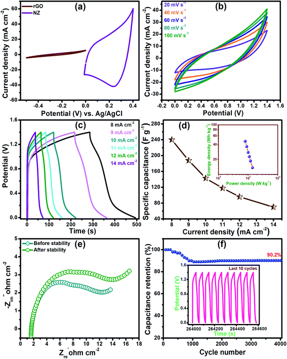
The practical applicability of the NZ-1 electrode was evaluated by fabricating an asymmetric device (ASC) with reduced graphene oxide (rGO) as a counter electrode in a PVA-KOH gel electrolyte. Fig. 7(a) shows the individual CV curves of the NZ-1 electrode within a potential window of 0 to 0.4 V and the rGO electrode within a potential window of 0 to −0.5 V (vs. Ag/AgCl) at a scan rate of 20 mV s−1. Fig. 7(b) presents a typical CV curve of the ASC device performed at different scan rates from 20 to 100 mV s−1. The shape of the CV curve remains the same for all scan rates, indicating the high-rate charge–discharge performance of the device. Furthermore, the shapes of the CV curves exhibit the acquisition of the capacitance due to the EDLC nature of rGO.34,35Fig. 7(c) presents the GCD graph of the NZ-1//rGO ASC cell at the current densities of 8, 9, 10, 11, 12, and 14 mA cm−2 within the operating potential of 0 to 1.4 V. The specific capacitances of the ASC device were calculated as a function of current density, and were found to be 240, 187.7, 142.9, 117.9, 96, and 70 F g−1 for 8, 9, 10, 11, 12, and 14 mA cm−2 current densities, respectively (Fig. 7(d)). The power density and energy density of NZ-1//rGO ASC are shown in the Ragone plots (inset of Fig. 7(d)). The device exhibits a maximum energy density of 46.66 W h kg−1 at a power density of 800 W kg−1, indicating its practical efficiency.36 At higher current densities, the accessibility of the electrolyte ions through the channels of the electroactive material is reduced, thereby providing insufficient time for the interaction of ions with the electroactive material. The Nyquist plot of the ASC device (Fig. 7(e)) exhibits low Rs (1.55 Ω), Rct (6.1 Ω), and W, indicating the excellent electrical conductivity of the device. Moreover, long-term cycling stability is a significant parameter for the practical application of a device. NZ-1//rGO ASC shows good cycling durability, and it retains 90.20% of the initial capacitance after 4000 charge–discharge cycles, as shown in Fig. 7(f). Fig. 7(f) inset represents the cyclic curves of the last ten cycles with nearly the same symmetric shape, demonstrating that the stability of the NZ-1//rGO ASC device is maintained due to the protection of the core material with the shell material.
4. Conclusions
In summary, the three-dimensional core–shell architecture of ZnCo2O4@NiO/FSSM with electrochemical durability has been synthesized by a simple, cost-effective, binder-free reflux condensation deposition for flexible all-solid-state asymmetric SCs and the effect of the concentration of the Ni precursor has been studied systematically. This work highlights the synergistic contributions of nanostructured ZCO and NiO as a core–shell ZnCo2O4@NiO microarray together and demonstrates the fast electron/ion transport kinetics and strong binding force between the current collector and electroactive materials. The core–shell arrays of NZ-1 significantly increase the specific surface area (134.79 m2 g−1), providing abundant channels, which permit the electrolyte ions to contact the underlying material. The binder-free ZnCo2O4@NiO electrode delivers a high specific capacitance of 882 F g−1 at 4 mA cm−2 current density and exhibits remarkable cycling stability (∼85% initial capacitance retention after 5000 charge–discharge cycles at 10 mA cm−2). The asymmetric supercapacitor device ZnCo2O4@NiO//rGO delivered a maximum energy density of 46.66 W h kg−1 at a power density of 800 W kg−1. The device revealed 90.20% capacitance retention after 4000 cycles. These results indicate that the ZnCo2O4@NiO architecture electrode is a promising functional material for energy storage devices.Conflicts of interest
The authors declare no conflict of interest.Acknowledgements
GPK is thankful to UGC, New Delhi, for the Research Fellowship (File No. F1-17.1/2016-17/RGNF-2017-18-SC-MAH-35301/) (SA-III/website). We are thankful to the Shivaji University, Kolhapur, for providing funds under the project “Research Strengthening Scheme” (SU/C&U.D. Section/94/1390). We are thankful to the Department of Chemistry, Shivaji University, Kolhapur, for providing the research facilities. We are thankful to Shivaji University Group for Advanced Research “SUGAR” for the helpful discussion.References
- Q. Bi, Q. Ma, K. Tao and L. Han, Dalton Trans., 2021, 50, 8179–8188 RSC.
- X. Lu, C. Shen, Z. Zhang, E. Barrios and L. Zhai, ACS Appl. Mater. Interfaces, 2018, 10, 4041–4049 CrossRef CAS PubMed.
- J. Xu and L. Wang, Sci. Rep., 2019, 9, 1–11 Search PubMed.
- W. Dang, X. Tang, W. Wang, Y. Yang, X. Li, L. Huang and Y. Zhang, Dalton Trans., 2020, 49, 10994–11004 RSC.
- Q. Wang, X. Qin, P. Jiang, J. Dai, W. Li and H. Gao, Mater. Res. Express, 2018, 5, 035503 CrossRef.
- K. Qiu, M. Lu, Y. Luo and X. Du, J. Mater. Chem. A, 2017, 5, 5820–5828 RSC.
- F. Yang, K. Zhang, W. Li and K. Xu, J. Colloid Interface Sci., 2019, 556, 386–391 CrossRef CAS PubMed.
- L. bo Jiang, X. zhong Yuan, J. Liang, J. Zhang, H. Wang and G. ming Zeng, J. Power Sources, 2016, 331, 408–425 CrossRef.
- J. Zhao, Z. Li, M. Zhang, A. Meng and Q. Li, ACS Sustainable Chem. Eng., 2016, 4, 3598–3608 CrossRef CAS.
- B. Cheng, W. Zhang, M. Yang, Y. Zhang and F. Meng, Ceram. Int., 2019, 45, 20451–20457 CrossRef CAS.
- T. Yi, Y. Li, J. Wu, Y. Xie and S. Luo, Electrochim. Acta, 2018, 284, 128–141 CrossRef CAS.
- Z. Sun, W. Ai, J. Liu, X. Qi, Y. Wang, J. Zhu, H. Zhang and T. Yu, Nanoscale, 2014, 6, 6563–6568 RSC.
- B. Mandal, M. R. Das and P. Mitra, J. Alloys Compd., 2019, 784, 877–886 CrossRef CAS.
- Y. Li, Y. Zheng, J. Yao, J. Xiao, J. Yang and S. Xiao, RSC Adv., 2017, 7, 31287–31297 RSC.
- R. Prasad and P. Singh, Catal. Sci. Technol., 2013, 3, 3223–3233 RSC.
- C. Yuan, X. Zhang, L. Su, B. Gao and L. Shen, J. Mater. Chem., 2009, 19, 5772–5777 RSC.
- Q. Ouyang, Z. Lei, Q. Li, M. Li and C. Yang, J. Mater. Chem. A, 2021, 9, 14466–14476 RSC.
- T. F. Yi, J. Mei, B. Guan, P. Cui, S. Luo, Y. Xie and Y. Liu, Ceram. Int., 2020, 46, 421–429 CrossRef CAS.
- G. P. Kamble, A. A. Kashale, A. S. Rasal, S. A. Mane, R. A. Chavan, J. Y. Chang, Y. C. Ling, S. S. Kolekar and A. V. Ghule, RSC Adv., 2021, 11, 3666–3672 RSC.
- C. Huang, C. Hao, Z. Ye, S. Zhou, X. Wang, L. Zhu and J. Wu, Nanoscale, 2019, 11, 10114–10128 RSC.
- L. Zhu, C. Hao, X. Wang and Y. Guo, ACS Sustainable Chem. Eng., 2020, 8, 11618–11629 CrossRef CAS.
- K. Song, W. Ai, Y. Zhang, Y. Zeng, Y. Yu, H. Qiao, Z. Liu, X. Shen, X. Hu and X. Hu, J. Mater. Chem. A, 2021, 9, 3007–3017 RSC.
- C. Huang, Y. Ding, C. Hao, S. Zhou, X. Wang, H. Gao, L. Zhu and J. Wu, Chem. Eng. J., 2019, 378, 122202 CrossRef CAS.
- G. P. Kamble, A. A. Kashale, S. S. Kolekar, I. W. P. Chen, B. R. Sathe and A. V. Ghule, J. Mater. Sci.: Mater. Electron., 2021, 32, 5859–5869 CrossRef CAS.
- J. Jin, J. Ding, X. Wang, C. Hong, H. Wu, M. Sun, X. Cao, C. Lu and A. Liu, RSC Adv., 2021, 11, 16161–16172 RSC.
- H. Shi, S. Chen, W. Shi, Z. Peng, J. Li, Z. Liu, G. Zhang and L. Liu, J. Mater. Chem. A, 2021, 9, 16852–16859 RSC.
- S. Liu and S. C. Jun, J. Power Sources, 2017, 342, 629–637 CrossRef CAS.
- X. Du, J. Sun, R. Wu, E. Bao, C. Xu and H. Chen, Nanoscale Adv., 2021, 3, 4447–4458 RSC.
- Z. Xia, V. Mishukova, S. Sollami Delekta, J. Sun, J. S. Sanchez, J. Li and V. Palermo, Nanoscale, 2021, 13, 3285–3294 RSC.
- C. Wei, H. Pang, B. Zhang, Q. Lu, S. Liang and F. Gao, Sci. Rep., 2013, 3, 1–5 Search PubMed.
- Q. Li, X. F. Lu, H. Xu, Y. X. Tong and G. R. Li, ACS Appl. Mater. Interfaces, 2014, 6, 2726–2733 CrossRef CAS PubMed.
- H. Gu, Y. Zeng, S. Wan, S. Zhang, Q. Zhong and Y. Bu, J. Mater. Chem. A, 2021, 9, 16099–16107 RSC.
- H. M. Lee, C. v. v. Muralee Gopi, P. J. S. Rana, R. Vinodh, S. Kim, R. Padma and H. J. Kim, New J. Chem., 2018, 42, 17190–17194 RSC.
- P. A. Shinde and S. Korea, Int. J. Eng. Res. Technol., 2017, 10, 532–537 Search PubMed.
- F. Zhu, Y. Liu, M. Yan and W. Shi, J. Colloid Interface Sci., 2018, 512, 419–427 CrossRef CAS PubMed.
- D. Li, Y. Gong, M. Wang and C. Pan, Nano-Micro Lett., 2017, 9, 1–9 CrossRef CAS PubMed.
- Y. Wang, C. Shen, L. Niu, R. Li, H. Guo, Y. Shi, C. Li, X. Liu and Y. Gong, J. Mater. Chem. A, 2016, 4, 9977–9985 RSC.
- G. P. Kamble, A. S. Rasal, S. B. Gaikwad, V. S. Gurav, J.-Y. Chang, S. S. Kolekar, Y.-C. Ling and A. V. Ghule, ACS Appl. Nano Mater., 2021, 11, 12702–12711 CrossRef.
Footnote |
| † Electronic supplementary information (ESI) available. See DOI: 10.1039/d1na00851j |
| This journal is © The Royal Society of Chemistry 2022 |

