
 Open Access Article
 This Open Access Article is licensed under a
 Creative Commons Attribution 3.0 Unported Licence
Solution properties of spherical gold nanoparticles with grafted DNA chains from simulation and theory
Fernando
Vargas-Lara
 *a,
Francis W.
Starr
a and
Jack F.
Douglas
b
*a,
Francis W.
Starr
a and
Jack F.
Douglas
b
aDepartments of Physics & Molecular Biology & Biochemistry, Wesleyan University, Middletown, CT 06459, USA. E-mail: lvargaslara@wesleyan.edu
bMaterials Science & Engineering Division, National Institute of Standards and Technology, Gaithersburg, Maryland 20899, USA. E-mail: jack.douglas@nist.gov
First published on 19th August 2022
Abstract
There has been a rapidly growing interest in the use of functionalized Au nanoparticles (NPs) as platforms in multiple applications in medicine and manufacturing. The sensing and targeting characteristics of these NPs, and the realization of precisely organized structures in manufacturing applications using such NPs, depend on the control of their surface functionalization. NP functionalization typically takes the form of polymer grafted layers, and a detailed knowledge of the chemical and structural properties of these layers is required to molecularly engineer the particle characteristics for specific applications. However, the prediction and experimental determination of these properties to enable the rational engineering of these particles is a persistent problem in the development of this class of materials. To address this situation, molecular dynamic simulations were performed based on a previously established coarse-grained single-stranded DNA (ssDNA) model to determine basic solution properties of model ssDNA-grafted NP-layers under a wide range of conditions. In particular, we emphasize the calculation of the hydrodynamic radius for ssDNA-grafted Au NPs as a function of structural parameters such as ssDNA length, NP core size, and surface coverage. We also numerically estimate the radius of gyration and the intrinsic viscosity of these NPs, which in combination with hydrodynamic radius estimates, provide valuable information about the fluctuating structure of the grafted polymer layers. We may then understand the origin of the commonly reported variation in effective NP “size” by different measurement methods, and then exploit this information in connection to material design and characterization in connection with the ever-growing number of applications utilizing polymer-grafted NPs.
The nature of the surface functionalization of nanoparticles (NPs) is the critical determinant of their behavior. Control over this surface layer, and its response to environmental conditions, such as temperature and pH, enables a broad range of desirable characteristics to be programmed into NPs. The physical nature of the grafted polymer layer is thus a matter of paramount interest in the numerous applications of polymer-grafted NPs. Here, we computationally investigate spherical NPs with a grafted polymer layer with particular emphasis on Au NPs grafted with single stranded DNA (ssDNA) as a model system of this kind. In biophysical applications of this type, and similar polymer-grafted NPs, the presence of the polymer layer is crucial for the targeted delivery of the NPs to tumors and tissues and tissue engineering applications,1–3 many developing therapeutic applications for the diagnosis and treatment of disease,4–9 the detection of pathogenic viruses in the environment and the treatment of viral diseases10 and the detection of environmental heavy metals and pollutants in the water supply11–13 and nucleic acids14 based on calorimetric sensing.15 Notable applications of polymer grafted NPs are also under development in connection with gene delivery, bio-imaging, photothermal and photodynamic therapies16–18 and RNA grafted NPs have been found to be effective in modulating the gene expression of plants19 so there are emerging applications of nucleic acid grafted NPs in agriculture.20 In addition to this tremendous activity in the field of medical science, there have also been many materials science applications using these particles21–27 in which there are complementary strand–strand interactions that allow for formation of functional self-assembled nanostructures and even macroscopic crystals.28,29 In short, polymer grafted NPs are undergoing an explosion of activity in many fields of science and technology.
While these manifold applications are scientifically interesting, and practically of great importance, the present paper is focused on understanding the conformational structure of the grafted ssDNA chains, and the collective properties of these grafted layers and the NP as a whole, as evidenced by static properties such the radius of gyration (Rg) of the polymer grafted NPs and hydrodynamic properties such as the hydrodynamic radius (Rh) and intrinsic viscosity ([η]). Qualitatively, the solution properties of polymer grafted NPs have much in common with star polymers in solution,30 which is natural since polymer grafted NPs in the limit that the particle core particle has a size comparable to the polymer statistical segment become equivalent to star polymers. We note that the magnitude of Rh has emerged as one of the best correlates with biophysically relevant physicochemical properties of polymer grafted Au NPs.31
Polymer grafted NPs also bear some relation to “microgel” particles formed by polymerizing microemulsion droplets,32–36 where the nearly spherical particles formed under moderate cross-linking density are often found to have a relatively dense core and diffuse periphery whose dimensions has a size on the same order of magnitude as the core region of these particles. A striking signature of NPs and polymers of this type is that the ratio of Rh/Rg can be much larger than the value of this ratio for hard spheres, 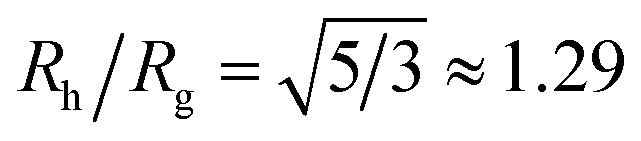 . Since the size of the solid cores of polymer grafted NPs are often larger or comparable to the thickness of the grafted layer and the grafting density of layers grafted from solution is normally moderate, polymer grafted NPs also tend to exhibit Rh/Rg values significantly larger than the hard sphere value. This trend of exceeding the hard sphere value is also predicted for dendrimer polymers at high generation number37,38 and we may expect this general tendency in hyperbranched polymeric materials. Values of Rh/Rg significantly greater than hard sphere value have also been observed in the molten globular state of collapsed polymer chains in solution39,40 and this phenomenon has also been observed in complexes polyethyleneamine and DNA of interested in drug delivery applications.41 The common thread in all these systems is occurrence of compact, nearly spherical particles having a dense core and diffuse outer periphery, a basic physical characteristic of polymer-grafted NPs.
Part of the motivation of the present study has come from the fact that many previous studies of polymer chains grafted on NPs and other surfaces have simply assumed that the chains adopt an extended conformation in which the grafted polymer chains take the form of polymer “brushes” in which the polymer chains are often imagined to adopt rod-like configurations oriented roughly normal to the surface to which they are grafted.42 Our simulations clearly show that the polymer chain conformations instead are more similar to free chains in solution for the grafting densities normally encountered in applications. Our computational method also enables us to extract other additional basic characterization information about these NPs, such as their Rh, Rg, and particle shape fluctuations quantified by the variance of these solution properties. We first describe the molecular model of the DNA grafted NP, and then the computational approach utilized to calculate the solution properties of these NPs and the conformational properties of the grafted polymer chains and the grafted layer as function of molecular parameters.
1 Model of single-stranded DNA grafted nanoparticles
We next describe our computational approach to simulate and characterize ssDNA-grafted NPs. We first utilize molecular dynamics simulations (MD) to generate ssDNA-decorated AuNPs configurations and then we use path-integral calculations43 to determine Rh for the configurations obtained from MD. This approach has been successfully applied to the study of more complex DNA-based structures.44We model each ssDNA chain as a set of “beads” (blue spheres on Fig. 1) connected by “springs”.45 One end of each chain is tethered to a spherical symmetric particle (orange sphere on Fig. 1(a)) representing a gold core NP in the experimental system). The Weeks–Chandler–Andersen potential (UWCA) to simulate the soft core excluded volume interaction among all the beads and between each bead and the NP core,
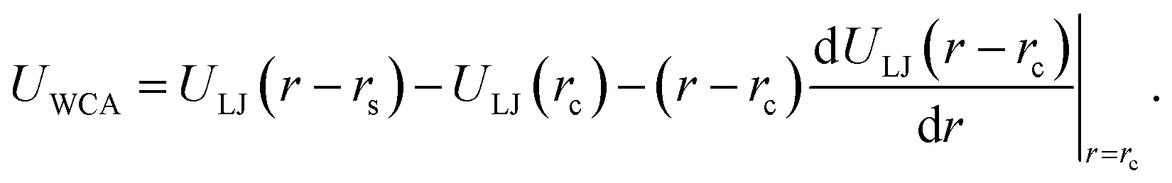 | (1) |
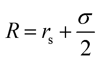 . For the blue beads we consider rs = 0 and we set σ = 0.65 nm (ref. 46) the diameter of the bead which is equal to the ssDNA base-to-base distance. This value is a representative one for the “effective” ssDNA chain diameter inferred from the translocation of ssDNA chains on solid-state nanopores.47 For the NP core, we vary from rs = 0.675 nm to rs = 4.675 nm corresponding to NPs having core radii from R = 1.0 nm to R = 5.0 nm. The beads along the chain and the first bead of each chain are taken to be connected by a finitely extensible nonlinear elastic (FENE) springs described by the potential,
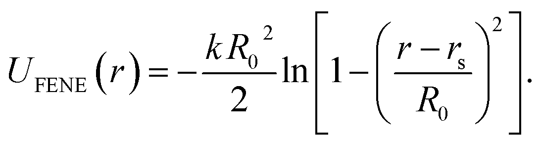 | (2) |
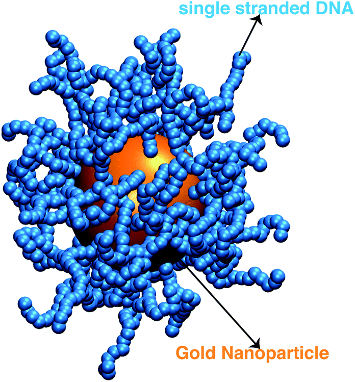 | ||
| Fig. 1 A representative configuration of a simulated ssDNA-grafted NP where the gold NP core is 5.0 nm in radius (orange sphere) and there are 60 ssDNA chains (connected blue spheres) grafted onto the NP core. Each ssDNA chain is formed by 18 T bases with lp = 2.0 nm. | ||
For this potential, we select k = 30/σ2 and R0 = 1.5σ. Additionally, we use a three-body angular potential (Ulin(θ)) to control the chain stiffness,
Ulin(θ) = klin(1 + cos![[thin space (1/6-em)]](https://www.rsc.org/images/entities/char_2009.gif) θ). θ). | (3) |
To model ssDNA, take klin = 1 to generate chains having persistence lengths lp = (2.0 ± 0.1) nm, which is a representative value for ssDNA chains. This estimate is suitable under the salt concentrations, ces ≥ 1 M NaCl,48 where charge interactions are largely screened. Here, lp is defined as the characteristic length, where the bond orientation correlation function 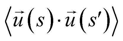 reaches 1/e. Here,
  is a unit vector tangent to the chain that is located at the position s. The ssDNA chains having chain lengths L = (5, 10, 18, or 40) Thymine bases (T), as in the experimental measurements. We vary the number of strands Nc attached to the NP core in the range 1 ≤ Nc ≤ 1000. An extension of this model to describe duplex DNA is discussed in ref. 49 and 50.
Our simulations utilize a canonical ensemble (NVT) with fixed reduced temperature, T* = 1.0ε/kB for all our simulations (kB is the Boltzmann constant) and it is controlled by using the Nosé–Hoover method.51,52 Our MD simulations were performed for ≥107 time steps using the Large-scale Atomic/Molecular Massively Parallel Simulator (LAMMPS)53 and we render the left panel of Fig. 1 using the Visual Molecular Dynamics (VMD) program.54 We compute properties for 103 different thermal equilibrated configurations (see Fig. 1(a)–(c)) using the path-integration program ZENO.43 These computations employ 105 random walk trajectories to achieve low uncertainty. We determine the average value and standard deviation σs for each property and uncertainty quantification is provided by ZENO and indicated by error bars in plots when the values are larger than the point size. The quality of fitting the simulation results to functional forms will be provided by its correlation coefficient value, ρ.
2 Numerical results for the hydrodynamic radius of single-stranded DNA grafted nanoparticles
In a previous paper,44 we utilized the present model to calculating Rh of DNA grafted onto Au NPs having prescribed DNA chain lengths and grafting densities and variable size of the Au core of the NPs. The grafting density in this work was estimated following a methodology of Mirkin and coworkers,55,56 in which the DNA chains were grafted onto the Au NPs in solution up to a point of “saturation” conditions, at which no further DNA chains could be grafted. Our direct comparison of our simulations to the observed values of Rh with the grafting density and the size of the bare NPs independently determined yielded good agreement in this initial study, and we also modeled how these NPs altered the dimensions of DNA origami sheets to which the DNA grafted NPs were attached.The extension of this work to describe the overage coverage of DNA on Au NPs independently requires a precise assay for estimating the number of grafted polymer chains on the NP surface, and corresponding dynamic light scattering measurements of DNA grafted NPs having a prescribed grafting density. Such well-characterized NPs and measurements are currently not available, and it is hoped that the present analysis stimulates an effort to synthesize and characterize such NPs. The methods described in the present study should also be helpful in the characterization of numerous other grafted NP systems that are currently being used in material science and medical applications.
We take advantage of our modeling to simulate polymer grafted NPs having grafting densities that are much higher than the “saturation grafting density” achieved when the polymer chains are grafted onto the bare metal NP from solution.55,56 The grafted density must ultimately be limited by the formation of a “brush-like” layer having a nearly uniform polymer segmental density, in which case the polymer-grafted NP becomes effectively similar to a hard sphere. This limiting hard sphere behavior can be achieved in the microemulsion derived NPs mentioned above in the limit of high grafting density33–36 or in polymer grafted NPs when the grafted polymer chains are grown directly from the surface of the NPs.57,58 However, the physical nature of the grafted polymer layer formed by grafting the polymer chains onto the NPs from solution has a rather different structure in which both the grafted ssDNA chains, and the grafted layer of the NP as a whole, exhibit appreciable conformational fluctuations (see snapshots of the simulated polymer grafted NPs in the inset of Fig. 2(a)). Thus, Rh of even a spherical NP having a fixed number of grafted polymer chains having a prescribed oligomer length will exhibit fluctuations that progressively diminish in magnitude as the polymer grafting density is progressively increased. Measurements of the fluctuations in Rh then offer some insight into the physical nature of the polymer grafted layer beyond a measure of the average thickness of the grafted layer. The fluctuations in the grafted layer shape also have independent interest for understanding the interaction between NPs in the presence of a fluctuating layer of grafted chains on NPs that can lead to self-assembly of the NPs into large scale string and sheet NP clusters in solution and in polymer nanocomposites.59,60 We address this fluctuation phenomenon in the next section.
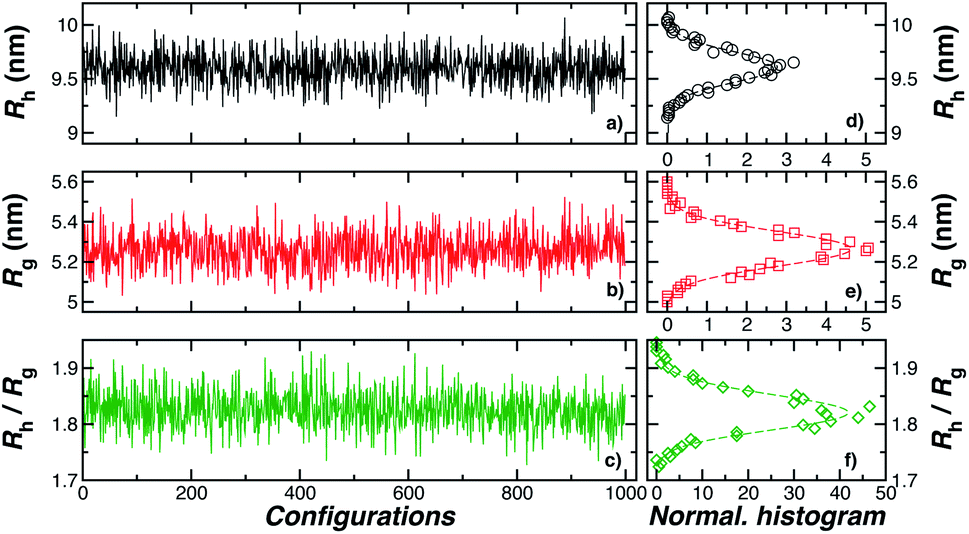 | ||
| Fig. 2 In panels (a), (b), and (c), the hydrodynamic radius Rh, radius of gyration calculations Rg, and the ratio Rh/Rg, respectively, for 103 configurations similar to the one shown in Fig. 1. Panels (d), (e), and (f) show the normalized histogram for the properties calculated in (a), (b), and (c) from the ensemble of configurations. Dashed lines in panels (d), (e), and (f) are a guide to the eye. | ||
As a final point relating to the range of application of our modeling, we note that progress has recently been made in creating DNA origami structures assemblies having diverse structural forms and in the modeling of these structures.61–63 The computational methodology based on numerical path integration (ZENO43) described in the present work should allow the facile computation of all these structures and a novel means to assess fluctuations in their geometry. Our emphasis on polymer grafted NPs is simply a particular model system from a much broader class of “nanoconstructs” that combine inorganic NPs and grafted chains involving nucleic acids such as DNA and RNA or polymers attached to functional drug molecules. The methods described in the present paper for characterizing ssDNA-grafted NPs have previously been successfully applied to duplex DNA solution properties over large mass range.64,65 We next focus on the solution properties of ssDNA-grafted Au NPs under physiologically relevant salt concentrations ≥0.1 M NaCl and pH 8.3,48 where electrostatic interactions can be reasonably neglected for the properties that we consider.
2.1 Size fluctuations for single-stranded DNA grafted nanoparticle
One of the basic physical features of polymer grafted NPs is that there size and shape fluctuates due the fluctuations of the individual flexible polymer chains and their collective fluctuations in the grafted polymer layer. These fluctuations have been observed to greatly influence the interparticle interactions in polymer grafted NPs in solution66,67 and polymer in polymer melts,59 and these fluctuations are no doubt germane to understanding their interactions with other molecules and to interfaces in a biophysical context. The extent of these fluctuations can be expected to depend on the length of the grafted chains, their stiffness, the grafting density on the NP, the polymer substrate interaction strength, etc. In the limit of very high grafting density, the so-called brush limit, we can expect these fluctuations to be small, the effect of polymer–surface interactions to be weak and the NP shape to be nearly spherical, but these fluctuations should be appreciable when the polymer chains are grafted onto the NP in solution, where interchain excluded volume interactions should limit the accessible grafting density.In this section, we perform illustrative calculations of some basic solution properties that characterize NP, Rg and Rh for ssDNA-grafted NPs having a range of grafting densities where we calculate the distribution of these properties and the variances of their distribution to quantify the extent of fluctuations in these basic solution properties. We find that extent of fluctuations first grows monotonically until the point where a fully percolating layer is formed and the variance of these properties then progressively decreases, albeit slowly, with increasing grafting density. The peak in this distribution apparently denotes the onset of “saturation” in the coverage of the grafted chains.
Fig. 3(a) shows the standard deviation of the distribution of hydrodynamic radius σRh as a function of the number of ssDNA chains N grafted to the NP, providing a quantification of the fluctuations in the shape of grafted NPs. Correspondingly, we see that σRh estimated from simulation exhibits a peak value, presumably reflecting the formation of a percolating grafted layer, and beyond this point σRh decreases progressively with increasing grafting densities, ultimately approaching the brush limit where σRh = 0. The experimental values of σRh beyond the saturation condition are roughly constant, although this quantity does exhibit significant fluctuations in the relatively high grafting density regime. We take the absence of a peak in σRh and the rough constant magnitude of σRh for large N as providing further evidence that the number of chains grafted to the Au NPs saturates for σRh = 30 when R = 5.0 nm.
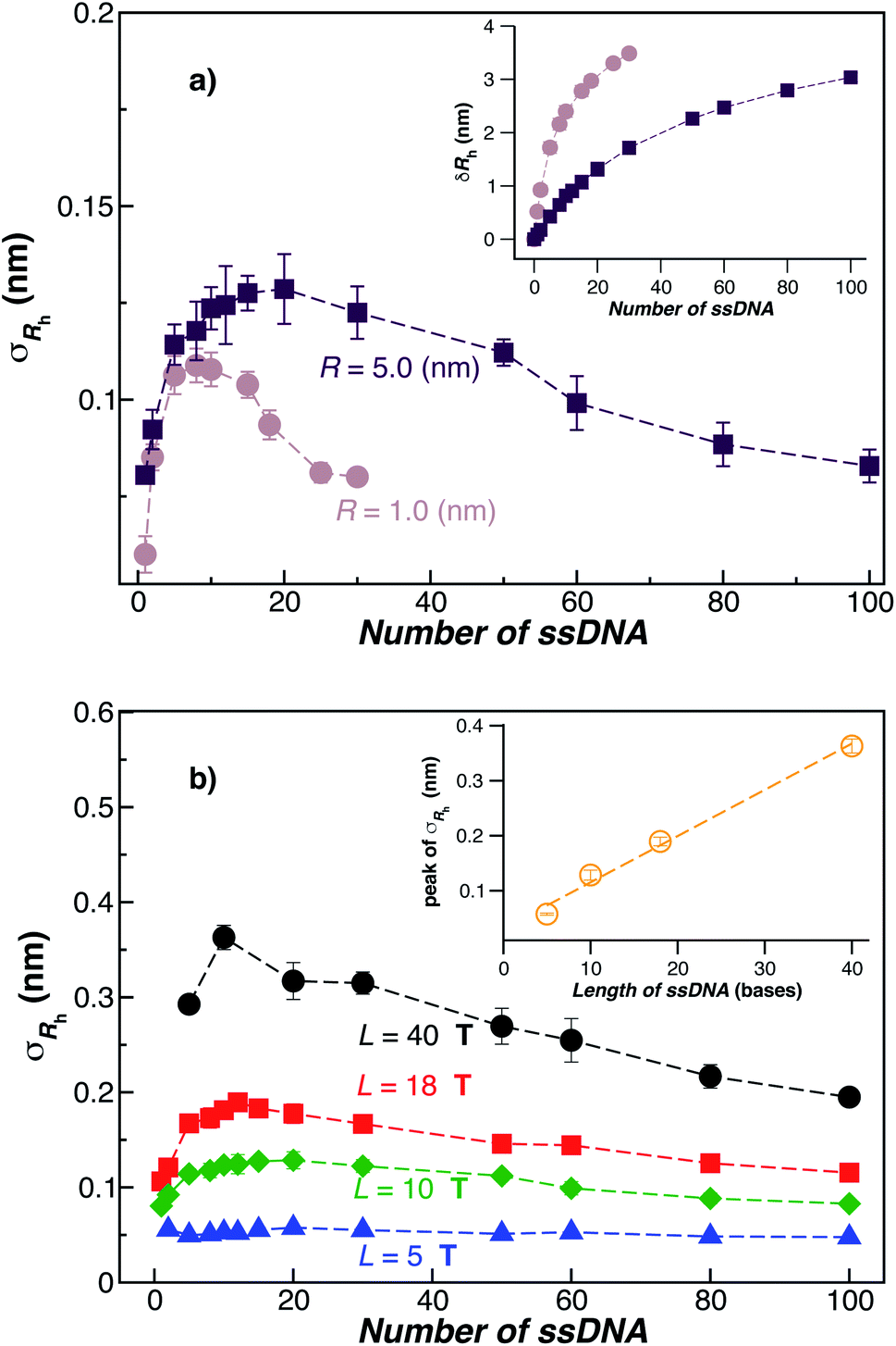 | ||
| Fig. 3 The standard deviation of the hydrodynamic radius σRh as a function of the number of ssDNA chains attached to the NP core. (a) In this panel, we fix the ssDNA chain length L = 10 T and the ssDNA chain persistence length lp = 2.0 nm and the core radius equals, R = (1.0 or 5) nm. The inset shows the difference δRh = (Rh − R) for the same NPs. The dashed lines are guide the eyes. (b) The radius of the NP core R = 5.0 nm is fixed in this plot and the chain persistence length lp = 2.0 nm and we vary the ssDNA chain length L = (5, 10, 18, or 40) T bases. Evidently, σRh shows a peak value as the number of grafted chains is varied whose magnitude increases roughly linearly with L (see inset). Dashed lines are a guide to the eye. | ||
The peaking of σRh in Fig. 3(a) with the number of grafted DNA chains depends on the NP core radius (R), the length of the ssDNA chains (L), as in shown in Fig. 3(b). The σRh peak height is higher for a larger NP core and for larger ssDNA chains. Correspondingly, the number of grafted DNA chains at which σRh peaks depends on the NP core radius R, an effect that evidently derives from the higher interfacial area of the larger NP. Similar trends are observed for the σRg of these ssDNA-grafted NPs (results not shown). We then see that it is possible to “tune” the NP shape and mobility fluctuations by varying the NP core size, polymer chain length and chain grafting density, which in turn influences the mutual interaction of these NPs and their interaction with other molecules and surfaces. It is our impression from limited data that the grafting saturation condition occurs near the conditions in which σRh peaks, corresponding to the formation of a “percolated” grafted layer in which the grafted chains start to come into contact and start to interact intermolecularly. However, this inference requires checking by further measurements in which is the polymer grafting density is better quantified. As noted before, this percolation transition has been directly imaged and modeled in the case of polymer chains grafted onto planar interfaces,68 and the sluggish chain dynamics associated with polymer topological interactions in adsorbing and desorbing polymer layers has also been investigated.69,70
We note that recent studies71–73 of the interaction of single stranded DNA polymer chains with Au NPs and planar Au surfaces without grafted DNA layers have indicated that this interaction is “exquisitely controlled by many factors including intermolecular forces, along with DNA composition and sequence”71 and the interaction is also strongly dependent on NP size, but it is not due to charge screening effects.73 The control of these interactions is important in many applications utilizing DNA grafted or adsorbed to Au NPs or planar surfaces and Koo et al.71 have reviewed this important topic with some of these applications in view. In our coarse-grained model of DNA grafted NPs, we model both excluded volume and polymer–substrate interactions by Lennard-Jones type interactions having a variable well-depth parameter describing the relative depth of the polymer–polymer and polymer–substrate attraction found in any particular system. This approach should apply well in cases where the interactions involved have a relative short-range interaction on the order of the segments of the polymer chains. While we expect this type of modeling to hold very well, we must admit that this type of modeling does not allow for an a priori prediction of the strength of the polymer surface interaction strength. This interaction parameter requires measurement for its determination under any solution condition of particular interest for a specific application. We note that the strong sensitivity of this interaction to NP size is a bit of a complication73 and this important effect is also prevalent in the context of the formation of bound protein layers on Au and other NPs. Lacerda et al.74 discuss this effect in some detail in the important case of the binding of representative blood proteins to Au NPS having a range of sizes where the size effect on the NP–protein interaction strength is quite apparent.
We suggest that it should be possible to gain further insights into this problem by studying the dimensions of grafted DNA layers by neutron reflectivity, as considered previously for synthetic polymers grafted to polymer layers,75 and by complementary molecular dynamics simulations.76 Recently, it has been shown that DNA grafted layers of high uniformity on Au surfaces can be synthesized,77 which could be used as the basis of this type of measurement. Neutron reflectivity studies on synthetic grafted layers have also shown that the polymer–substrate interaction can be controlled, and the dimensions of the grafted layer can controlled by “back-filling” the regions of the grafting substrate by very low mas polymers with end-groups that tune the polymer–surface interaction.78 This approach should be helpful in engineering of the polymer–surface interaction for numerous applications using DNA and other surface-grafted polymers bound to either through chemical bonds or physical association to substrates. We note that this approach can also be used to control the binding of polymers with grafted polymer layers onto interfaces.79
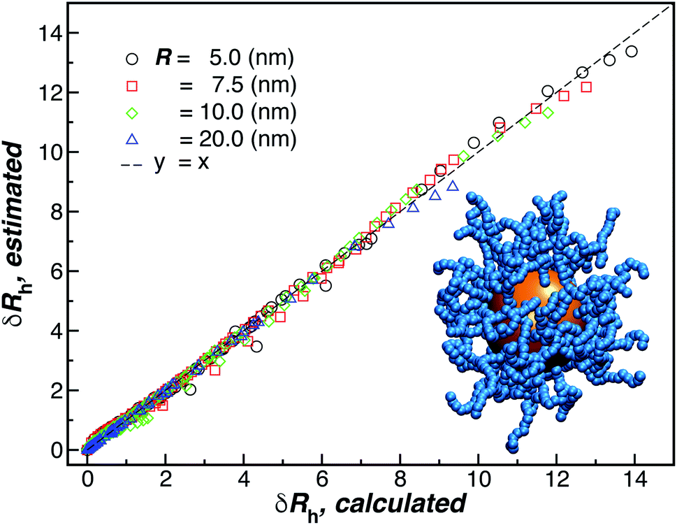
As a final remark, we emphasize that very few modeling studies of polymer-grafted NPs even consider the existence of a variable polymer–surface interaction strength in layers of polymers grafted to NPs and planar surfaces. Apparently, this approach to modeling these polymeric structures reflects a presumption that grafted polymer layers have a “brush-like” structure in which there is little opportunity to for the chain segments to access the boundary region so that the chains have little capacity to respond to this interaction by changing the conformational structure of the grafted layer. One of our main points in showing the data in Fig. 4 is to illustrate that the size of the NPs with grafted polymer layers having a grafting density and chain lengths representative of those utilized in measurements and applications of DNA grafted NPs depend sensitively on the NP–polymer interaction. This is just one of the implications of the deviation of real grafted layers from the idealized brush model often assumed in modeling polymer grafted NPs and interfaces. This sensitivity of the NP to the actuation of changes in the dimensions of the grafted layer by introducing molecules that segregate to the grafting surface, thereby altering the polymer–substrate interaction strength,78 implies that other molecules in solution (“impurities”) could affect the performance of these NPs in applications.
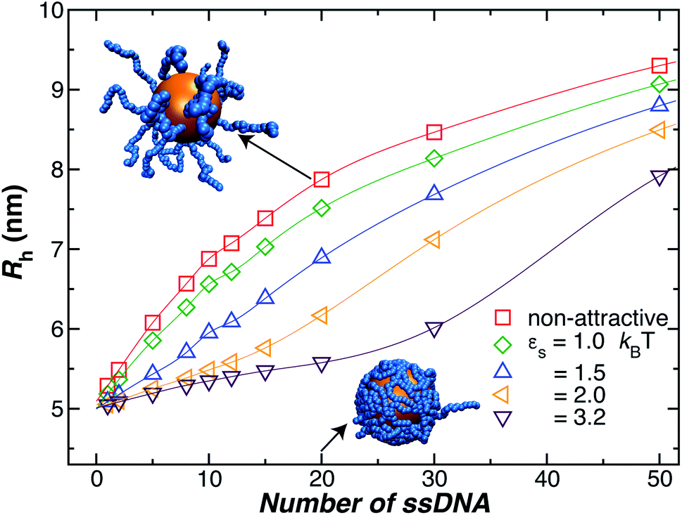 | ||
| Fig. 4 Influence of the polymer–nanoparticle interaction strength on the hydrodynamic radius Rh for a 5.0 nm NP as a function of the number of grafted strands, where each strand is formed by 18 T bases. We vary the interaction strength between the NP core and the ssDNA bases by modifying εs, as it is shown in the legend. We see that attractive interactions can lead to an appreciable change in the thickness of the grafted polymer layer, the effect is especially significant at lower grafting densities. Lines guide the eye. | ||
2.2 Influence of single-stranded DNA–nanoparticle core interaction
Another factor that may affect the configuration of the grafted chain layer is the influence of any attractive interaction between the surface of the Au NP core and the polymer grafted to the NP on the conformation of the polymer in the grafting polymer layer. Such interactions are normally neglected in ideal polymer “brush” layers, but, as we shall see, these layers are normally not “brush-like”, and it is important to assess the effect of the polymer–NP interactions on the size of grafted NPs.In Fig. 4, we show the influence of the strength εs of an attractive interaction between the NP core and the grafted chains on Rh. We see that this attractive interaction between the grafted polymer layer and the NP surface can evidently lead to an appreciable change in the thickness of the grafted polymer layer and the size of the NP, an effect that is especially large at lower grafting densities. When we compare the curves to our measurements for a 5 nm Au NP, we infer these interactions must be weak for our 5 nm radius NP. However, previous work has shown that the attractive interactions become stronger for blood proteins and much larger Au NPs,74 and we inferred a similar effect in our earlier work in Au NPs with grafted DNA.44 While the polymer–surface interaction does not appear to be a significant effect in our measurements on NPs as small as those considered in Fig. 4, we need to keep in mind that these interactions can be highly relevant to the thickness of grafted polymer layers in general.71,80
2.3 Influence of single-stranded DNA length
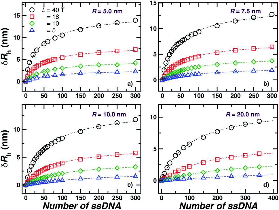
We next present our simulation results for NP decorated strands having different length, L = (5, 10, 18, or 40) T bases and different number of strands N in Fig. 5. We start by fixing the NP core size R = 5.0 nm and varying the number of ssDNA attached to the NP core. As expected, we find the change in Rh with increasing N is higher for larger chains.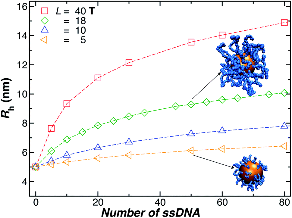 | ||
| Fig. 5 Nanoparticle hydrodynamic radius, Rh, as a function of the number of ssDNA chains attached to the NP core with radius r = 5.0 nm. We vary the length of the chain L, as indicated in the legend. The open symbols are simulation results and the dashed lines guide the eye. | ||
The primary reported evidence that has been interpreted as implying a “rod-like” ssDNA chain conformations of the chains grafted on the NP surface has been surmised based upon measurements of the effective Rh (obtained from the Stokes–Einstein relation and diffusion coefficient estimates from dynamic light scattering) changes relative to Rh of the NP core. In particular, a linear scaling in δRh = Rh − R with length of the grafted polymer has been interpreted as implying the polymer chains are standing up straight as in the bristle of a paint brush.81 We indeed find this linear scaling in Fig. 6(a) for our R = 5.0 nm NP having grafted ssDNA chains onto the surface of a 5.0 nm radius NP core, but this apparent linear scaling certainty does not imply that the chains have been highly stretched “bristle-like form” shown in many cartoons of polymer brush layers. Fig. 6 shows Rg of the individual chains in the grafted layer for N = 20, 60, and 100 indicate that Rg is relatively unchanged from its value in solution, where the M scaling of Rg in solution is consistent with a short flexible polymer, Rg ∼ M0.65. Interchain and self-excluded volume interactions are apparently not strong in these grafted chain layers so that the brush cartoon of highly extended polymer chains is the grafted layer is not supported by our simulation observations, despite the nearly linear scaling of δRh in Fig. 6(a).81
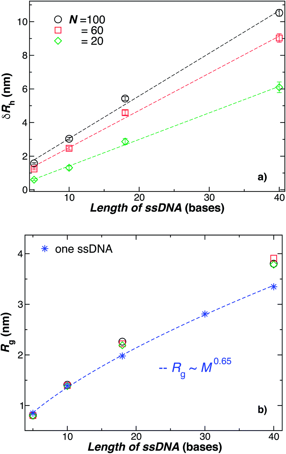 | ||
| Fig. 6 Comparison of the change in the NP radius from the presence of grafted polymer layer and the size of an individual polymer in solution. (a) The change in the hydrodynamic radius, δRh = Rh − R, for a 5.0 nm in radius NP having grafted with 20, 60, or 100 ssDNA chains for a range of the ssDNA chain lengths, where the ssDNA chains have 5, 10, 18, or 40 T bases. The symbols are the data, and the dashed lines are linear regressions to the data with correlation coefficients, ρ ≥ 0.9. The nearly linear scaling of δRh can give the misleading impression that the ssDNA chains are adopting a rod-like configuration.81 (b) The radius of gyration Rg for chains grafted onto the same NPs as in panel (a) (black circles, red squares, green diamonds) in comparison to Rg for individual ssDNA chains in solution (blue stars). The blue dashed line is a fit to the blue stars using a power law relation from where we obtain the scaling exponent ν. Here, ν ≈ 0.65 ± 0.007 with ρ = 0.99. We again conclude that the ssDNA chains attached to the NP core have a configurational structure similar to ssDNA chains in solution. | ||
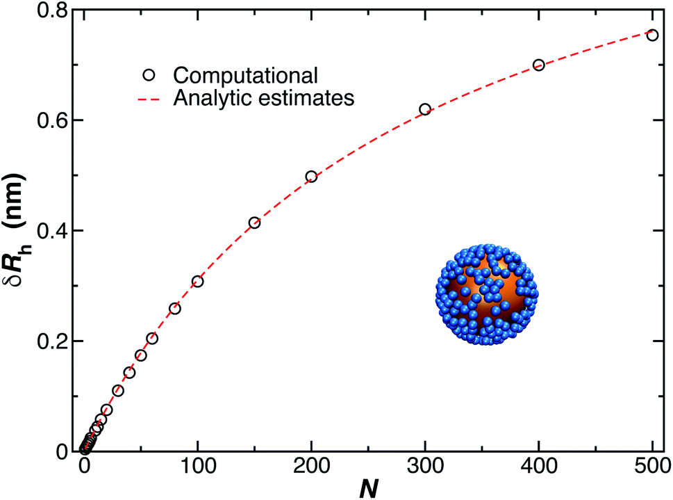
2.4 Influence of nanoparticle core size
The increase of Rh arising from an increase of the NP core size is rather easy to understand and this case has been discussed in a previous paper in the limit where a “saturated” layer of DNA chains was grafted onto the Au NP surfaces.44 For a given grafting density, the intercept of a plot of Rhversus NP core size is a reasonable estimate of the thickness of the interfacial layer. However, the treatment of the case where the surface grafting density is not in the saturated layer limit is complicated by the uncertainty in estimating the surface grafting density when the NPs become much larger than a scale on the order of a few nm. For larger particles, we expect the attractive interaction between the Au core and the ssDNA chains to rapidly form a saturation polymer layer on the NP surface, making experimental estimates of the polymer grafting density highly uncertain. The signature of this effect is that Rh of the polymer-grafted NP has a size consistent with a saturating coverage almost regardless of the estimation of the nominal number of grafted polymer chains based on the method described in Section 2.1. There is an evident need to improve experimental estimates of the polymer grafting densities to account for the significant roles of the polymer grafting densities to account for the significant roles of the polymer–NP interfacial interaction and the polymer–polymer excluded volume interaction in forming these layers. Hydrodynamic measurements offer some insight into this problem, as discussed in Section 5.3 Theoretical model for the hydrodynamic radius of spherical nanoparticles with grafted particles and polymers
We next develop a general model for the dependence of Rh on chain length, core size, and chain grafting density that can be used in this and other contexts where such polymer-grafted NPs need to be characterized. In particular, we provide useful relationships for the estimation of Rh as a function of the ssDNA-grafted NPs structural parameters. In the next subsections, we derive a relationship that describes Rh for our model NPs that should be transferable to Au NPs having arbitrary grafting densities and chain lengths, as well as many other types of polymer-grafted NPs in which the shape of the particle core and the molecular nature of the grafted polymer layer is varied. This development occurs through a succession of models a series of models of increasing molecular faithfulness of the individual polymer chains grafted onto a spherical nanoparticle (NP) structure (spheres, ellipsoids, semi-flexible polymer chains with excluded volume interactions), and we then extended the model to describe collections of these coarse-grained model polymers using a combination of molecular dynamics simulations of the conformational structure of the grafted polymer layers and the path-integration program ZENO.43 The reason for this procedure is the extreme complexity of the hydrodynamic properties of such layers and this approach allows us to systematically build on known results, which progressively extend and then validate by simulation, ultimately arriving at description in which we can describe the hydrodynamic properties of polymer grafted NPs where the chain conformational structure is explicitly considered, with some confidence.3.1 Spherical nanoparticle with a single small grafted sphere
It is well-known that Rh of a spherical particle equals its radius, Rh = R, and as a first step, we consider how Rh of a spherical particle changes due to the addition of another small spherical particle having a radius r. First, consider the simplest case where the spheres are tangential, so that the center-to-center distances is always r + R (see Fig. 8). To determine the change in the hydrodynamic radius, δRh = Rh − R, of spherical particles due to the presence of the second one (binary system), we recall the hydrodynamic–electrostatic analogy proposed by Douglas and coworkers37,43 that states the Rh of an object is approximately equal to the capacity C of a conducting particle having the same shape,| Rh ≈ C, | (4) |
We can take advantage of the exact solution for the self-capacity of two-touching spheres having radius, R and r, respectively, given by Russell82 to estimate Rh for two touching spheres of generally different diameter,
 | (5) |
 | (6) |
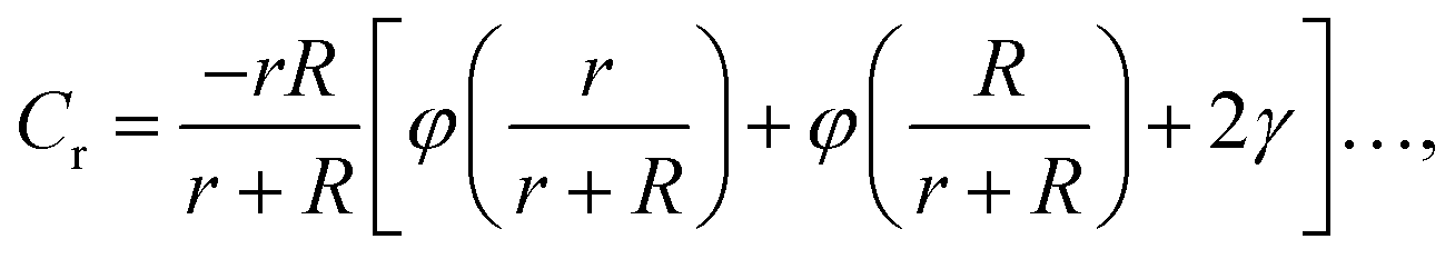
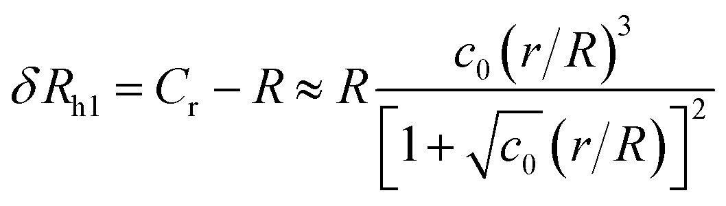
The constant c0 is fixed by the exact result for Cr in the limit of r/R → 0 and Cr(r/R = 1) to obtain an approximation for Cr, and thus δRh that cover a large range of r/R. In particular, solving the Laplace's equation with constant boundary conditions on the surface for two-tangential spheres having the same radii by consistency leads to precise prediction, Cr = 2ln(2) = 1.386…R, so that c0 = 2.69678 (the best numerical estimate83,84 of δRh1 for two spheres having the same radius equals = 0.384R). Fig. 7 shows the results for δRhr/R as a function of the ratio rh/R, where rh is the radius of the small sphere. The symbols were obtained by using the path-integration program ZENO, indicated as a line in eqn (6). No fitting parameters were required, demonstrating the predictive nature of eqn (6) over a large range of r/R.
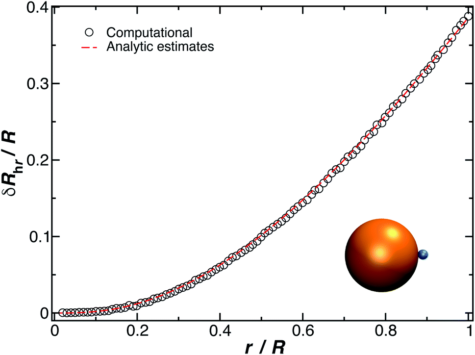 | ||
| Fig. 7 Normalized change in the hydrodynamic radius for a spherical particle (gold sphere with radius, R) with an attached small spherical particle (blue particle). The open symbols are calculations, and the dotted line is given by eqn (6) with ρ = 0.99. | ||
3.2 Spherical nanoparticle with a grafted small ellipsoid
We now turn our attention to the calculation of the change in Rh when an ellipsoidal particle rather than a sphere is attached to the surface of the relatively large sphere, δRhe (see Fig. 8). Here, the ellipsoid is defined by its three semiaxis a1, a2, a3 and for practical purpose, we only consider prolate ellipsoids, a1 = a2, < a3. For this case, we found the parameter c0 on eqn (6) depends on the ellipsoid axial ratio as = a3/a1. Fig. 8 shows the results for δRhe as a function of the ratio rhe/R, where rhe is the Rh of the ellipsoid. Here, we vary the axial ratio as it is indicated in the legend of the main figure. The symbols were obtained by using the path-integration program ZENO and the lines are fits to eqn (6). We obtain the parameter c0 from the fits of the data to the eqn (6) and we find that it follows the empirical relationship extending the limiting spherical particle result in eqn (6),| c0 = (2π − 1)ln(1 + as/e) + 1.041, | (7) |
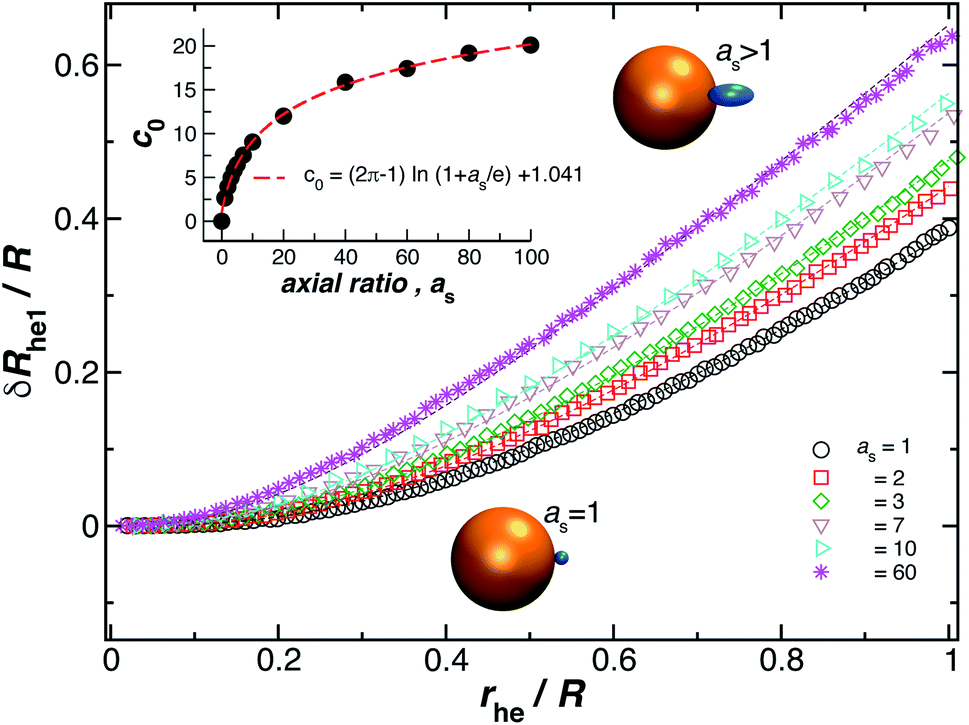 | ||
| Fig. 8 Normalized change in the hydrodynamic radius for a spherical particle (gold sphere) with an attached ellipsoidal particle (blue ellipsoid) having an axial ratio, as. The open symbols are calculations and the dotted lines are fits to eqn (6), with correlation coefficients, ρ ≥ 0.96. From here we obtain the values of c0 and we plot them as a function of as in the figure inset. The red dotted line indicates a fit to eqn (6) with ρ ≥ 0.99. | ||
3.3 Spherical nanoparticle with a single-stranded DNA grafted chain
Fig. 9 shows the change in the Rh for a spherical particle (gold sphere) due to the addition of ssDNA chain (chain of blue beads in figure). The open symbols are calculations and the dotted lines are plots of eqn (6) considering two limiting values of c0. We now estimate δRh1, based on a model in which each ssDNA chain is oriented with the long axis defined by the long axis of Rg tensor of the polymer radius of gyration tensor is oriented perpendicular to the local attachment point on the sphere to which it is attached. The lengths of the principal axes of the radius of gyration tensor (Λ1, Λ2, Λ3) are obtained from the diagonalization of the radius of gyration tensor of the ssDNA in solution and the orientation of this effective ellipsoid is taken to be defined the long axis of this ellipsoid, which may be viewed a as coarse-grained model of the attached chain. Here we use the convention Λ1 ≤ Λ2 ≤ Λ3, and approximate the “axial ratio” as,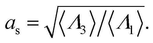 | (8) |
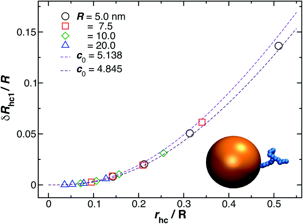 | ||
| Fig. 9 Normalized change in the hydrodynamic radius for a spherical particle (gold sphere) due to the addition of ssDNA chain (blue connected beads). Here, rhc is the hydrodynamic radius of an isolated polymer chain in solution. The open symbols are calculations and the dotted lines are plots of eqn (6) considering two limit values of c0 described in the legend. | ||
Fig. 10 shows a comparison between the estimated values for δRh1/R obtained by combining eqn (6) and (8) and the values calculated by using ZENO. We find that we can obtain a quite good approximation of Rh of a particle with a single grafted chain.
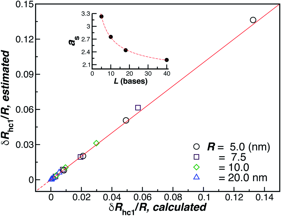 | ||
| Fig. 10 Analytic versus simulated estimates of δRhc1/R (ellipsoid approximation). The red line is a fit to the identity function y = x, with ρ = 0.99. The inset shows the axial, eqn (8), for the ssDNA chains in solution as a function of the chain length. | ||
3.4 Spherical nanoparticle with many grafted small spheres and ellipsoids
We next graduate to the more physically interesting case of NPs having many attached particles or polymers. Building on the analysis before, we first consider δRh for N small particles attached to the surface of the NP core particle. Within the electrostatic-hydrodynamic analogy indicated above, this problem is formally equivalent to the capacity of N capacitors on the surface of a sphere,85 which has been treated in previous studies of diffusion-limited reaction on the surface of cells. In particular, for a sphere with N randomly attached small spheres, we estimate δRh by,86–88 | (9) |
 is the saturation values of δRh, when the sphere is fully covered by a large (N ≫ 1) number N of small spheres, and
  , where δRrh is the single attached sphere property calculated above. We note that if r ≪ R,
  and if N = 0, δRh = 0.
Eqn (9) arises in the crossover description of the hydrodynamics of polymer chains and this functional function has been termed the “hydrodynamic penetration function”,86 a measure of the strength of the hydrodynamic interaction within the polymer coil. Here this term refers to the degree of hydrodynamic interaction strength within in the interfacial layer around the NP. The limit Z arrow infinity corresponds to the so-called “non-draining” limit where the layer is surface layer becomes a hydrodynamically impenetrable layer of uniform thickness. The crossover function in eqn (9) arises in many types of interacting polymer problems in addition to the hydrodynamic properties of polymers in solution–polymer excluded volume interactions, surface interacting polymers, capacity of complex conducting polymeric structures, etc.86,89
Fig. 11 shows a comparison between the computational estimates (black circles) of δRrh and the analytic estimates (red dashed line), eqn (9), where Cr and Rh are equated.
 | ||
| Fig. 11 Change in the hydrodynamic radius for a spherical particle (gold sphere) due to the addition of N small spherical object (blue beads). We find the data is well described by eqn (9) (red dashed line, with ρ = 0.99). | ||
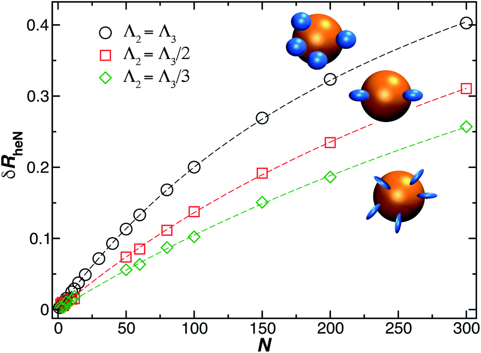
The treatment of many grafted ellipsoids or other objects of fixed and general shape to a “bare” supporting particle proceeds in much the same way as many smaller spherical particles bound to a sphere. In particular, we calculate δRrh for ellipsoidal grafted particles by sequentially positioning N such particles randomly on a sphere and calculating Rrh of the grafted NP system after each particle is added. We may model a grafted polymer layer in a crude coarse-grained approximation by taking the ellipsoids to be prolate in form and oriented with their long axis of dimensions oriented normal to the supporting surface at the point of the ellipsoid attachment. Flexible polymers in solution are known to exhibit an ellipsoidal average shape in with appreciable anisotropy90,91 and fluctuations in their anisotropy have also been observed.92 We can expect the repulsive interchain interactions in the grafted layer to only enhance this tendency, which is the basic concept behind the “brush” picture of such grafted layers.76,77 In general, the shape anisotropy depends on polymer topology, chain stiffness, and polymer excluded volume interactions.30,49,64,93,94
The model of ellipsoidal chains grafted to a spherical particle in a perpendicular orientation is intended to describe grafted chains that do not have a strongly attractive interaction with the surface, and in the case of the presence of such attractive interactions, e.g., when a polymer becomes bound to the substrate, we can simply modify the model so that the length of the ellipsoid of revolution along its symmetry axis (quantified by the largest eigenvalue of the radius of gyration tensor of the ellipsoid, Λ3) is made smaller than in the transverse direction (quantified by the smallest eigenvalue of the radius of gyration tensor of the ellipsoid, Λ3), i.e., the bound polymer is then modeled by an oblate ellipsoid of revolution. Fig. 12 shows the results of our method, as just described for δRrh, where we model the ellipsoids as being prolate and oriented normal to the surface of the spherical particle surface. This is the most relevant case for modeling DNA molecules grafted to Au NPs. We see that eqn (9) describes our estimated values of δRrh very well, even when the axial ratio of the ellipsoid is varied over a large range.
 | ||
| Fig. 12 Change in the hydrodynamic radius for a spherical particle (gold sphere) due to the addition of N small ellipsoidal objects (blue particles). We find the data is well described by eqn (9) (dashed lines, with ρ ≥ 0.99). | ||
We should mention that many NPs form “auto-grafted” layers when exposed to a solution environment containing proteins and other biological macromolecules that “largely defines the biological identity of the particles”.95,96 There has been tremendous and ever-growing interest in the formation of this type of “corona” layer in connection with the targeting of NPs to various tissues in a medical science context97 and in understanding of toxicity of NPs in some types of NPs, which can be greatly affected by the nature of this interfacial NP coating.98,99 The nature of the interactions governing the formation of these layers can be subtle, and even NP size,74 other solution conditions being equal, can greatly alter the strength of the NP interaction with the binding proteins. It is this type of grafted polymer layer that is of greatest interest in medical and environmental impact studies,100,101 and thus in understanding and modeling the ultimate biological activity of NPs released into the environment or introduced into the body.102,103 There has also been a great and ongoing efforts aimed at the difficult problem of quantifying the interactions between NPs and proteins.97 It is further notable that the hydrodynamic size, i.e., Rh, of NPs is strongly implicated in their cellular uptake.104
3.5 Applications of particle with randomly attached smaller particles
The model of a spherical particle with smaller particles attached at random to its surface has been widely utilized as a basic model of the formation of protein layers on NPs, where this modeling is combined with dynamic light scattering modeling of Rh of the NP with bound proteins and thermodynamic modeling of the number of “bound” polymers based on simple Langmuir adsorption theory, extended to account for the cooperativity of binding (Hill model).60,105–108 Cooperativity in molecule binding that naturally arises from many internal degrees of freedom and multifunctionality of protein binding to interfaces.109,110 In particular, the average number of “bound” particles N is normally modeled as60,105–108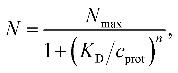 | (10) |
We emphasize that previous studies of Rh of proteins bound to their surfaces60,105–108 have completely neglected the role of hydrodynamic interactions on the Rh of NPs with bound proteins, but the analytic modeling of Rh has rather involved a simple interpolation relation between the limits of no attached proteins (the “bare” NP) and uniform coated sphere model as an approximate description of the high protein coverage limit. The utilization of eqn (9) above should allow a physically more faithful description of the hydrodynamic properties of this important class of naturally occurring grafted NPs. We finally note that the ZENO program allows the treatment of arbitrarily shaped NPs and the “grafting” of particles having general shape and orientation to these particles, based on modeling of the attachment process of these particles. Vargas-Lara et al.94 has discussed the calculation of the and intrinsic viscosity of particles and polymers having general shape, illustrating the application of ZENO in this generalized mode. We next turn to the modeling of many grafted polymer chains to a NP surface.
3.6 Spherical nanoparticle with many grafted small chains
We finally consider the case in which the spherical NP is “decorated” with Nc ssDNA strands where each ssDNA strand has a fixed length L. For this case we find that eqn (9) must be modified to account for the polymeric nature of the grafted layer components. We find that for this case δRh follows the relationship, | (11) |
 , where δRhc1 is enhancement of Rh due to a single chain and
  is the saturation limit of the enhancement of Rh by the grafted layer (
 is specified below). The “cross-over” exponent φ accounts for chain-core and chain–chain interactions, and we find below that this quantity empirically ranges from φ = 0.58 for grafted flexible polymers to φ = 0.58 for grafted spheres. Fig. 13 shows the simulation results for all systems considered in this study (particles interacting attractively) along with fits to eqn (11).
 | ||
| Fig. 13 Comparison between all simulated systems (open symbols) and fits to eqn (11) dashed lines (ρ = 0.98). We find good agreement between eqn (11) and calculation results. | ||
Fig. 14(a) and (b) indicate that there are two coverage regimes, one for rhc/R ≤ 0.14 where the chain–core interaction is weak so that φ = 1, and a second regime, rhc/R > 0.14, where φ decreases nearly linearly with increasing rhc/R. Evidently, the curvature of the spherical core particle exerts an appreciable effect on the extent of the grafted layer contribution to Rh. We also see that the saturation coverage  follows a power law dependence on the ratio L/lp, where lp is the polymer persistence length, and the effective power νh is a function of the ratio, R/rc. Here we follow a similar procedure to our previous study of DNA polymer chains under strong geometrical conditions between two interfaces89 in developing an approximant for the average thickness of the grafted layer,
  , and
, and
 | (12) |
| νh = [1 + 0.43(R/6rc)]/[1 + 0.70(R/6rc)]. | (13) |
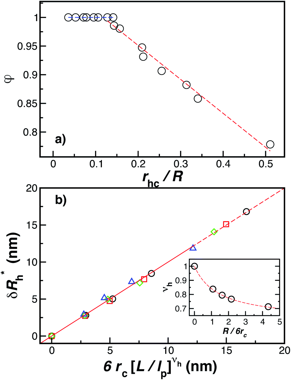 | ||
Fig. 14 The parameters (a) φ and (b)  as a function of the DNA-grafted structural parameters. The inset in panel (b) shows the R dependence of νrmh. Dashed lines are guide for the eye. as a function of the DNA-grafted structural parameters. The inset in panel (b) shows the R dependence of νrmh. Dashed lines are guide for the eye. | ||
Finally, we show in Fig. 15 all our simulation observations of Rh of polymer-grafted NPs can be described by the universal scaling relation, Rh = Rh(core) + δRh, where δRh is defined by eqn (11). This expression can be recognized as rather similar to the Kirkwood–Risemann mean-field theory for Rh of a flexible chain, which again has the same cross-over form,85,86,113,114
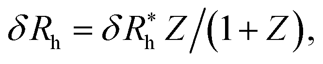 | (14) |
 is proportional to the chain Rg and the hydrodynamic interaction strength parameter Z. Here,
  is the limit of strong hydrodynamic interaction where the polymer domain becomes hydrodynamically “impermeable” where the hydrodynamic interaction strength Z scales as the number of chain segments N divided by Rgd−2 where the d − 2 power reflects the dimensional scaling of capacity/hydrodynamic radius.85 A renormalization group (RG) calculation of Rh of flexible polymers also leads to eqn (11) as a leading expansion in the variable ϕ, which equals, ϕ = (4 − d)/2 ≡ ε/2, where d is the spatial dimensionality.115,116 The “cross-over” expression for Rh of flexible polymers as function of the hydrodynamic interaction and excluded volume interaction strength becomes more complicated in functional form beyond the leading order in the ε-expansion.115,116 Fortunately, variable hydrodynamic interactions fluctuations are normally less prevalent in polymer-grafted NPs having a moderate grafting density than isolated flexible polymer chains in solution, making the mean-field cross-over expansion, eqn (11), a rather good approximation.
 | ||
| Fig. 15 Comparison between δRh values obtained by simulations versus the ones estimated by using eqn (11). The dashed line corresponds to a linear relation y = x with ρ = 0.98. | ||
4 Other nanoparticle solution properties relating to “size” and average shape
4.1 Ratio between the hydrodynamic radius and radius of gyration
Another important quantity that helps the characterization of these particles constitutes the ratio Rh/Rg, where Rg is the radius of gyration of the particle. In particular, for a spherical particle equals, . Experimentally, this quantity can be obtained by X-ray and neutron scattering and depending on the technique utilized, and the contrast, Rh/Rg for the DNA-grafted NP may vary. Fig. 17 shows Rh/Rg calculated numerically considering the scatter particles having equal contrast than the nanoparticle core (red squares), or neutrons (blue triangles).
We find that the mean dimensions of the grafted chains are not significantly altered from their random coil conformation in solution even at saturation coverage, so that the term “brush” is potentially misleading. In particular, we find that an approximately linear increase of Rh with the length of the grafted chains at a saturation coverage cannot be taken to imply that the grafted chains adopt highly extended worm-like chain configurations as often suggested in cartoon models of grafted polymer layers. As one of the most important results of our paper, we have developed a general cross-over function describing Rh for NPs having variable core size, number of grafted chains, and the variable grafted chain length, based on a consideration of the chains as spheres or ellipsoids. We validated our results against numerous simulations for these structures, and against experiments under conditions where the interfacial grafting densities could be readily investigated. We expect these results will be useful in the characterization of surface-grafted NPs.
Our numerical calculations indicate that the fluctuations in the shape of the polymers in the grafted layer can give raise the appreciable fluctuations in Rh about its average values even when the NPs are monodispersed in NP core size, have the same number of grafted chains and the grafted chains all have the same length. With increasing grafting density, the variance of these fluctuations first increases and peaks and they decrease as the layer becomes fully saturated. We expect these estimates of the fluctuations in the shape of NPs to be important for understanding the interactions between the NPs and their interactions with biological molecules and structures.
The quantification of the influence of the interaction of the grafted chain and the surface of the NP core is also a novel aspect of the present work. We find that this interaction can greatly influence the effective NP size (Rh), but in the case of Au NPs having a size truly in the nanometer scale, i.e., 5 nm, this effect is apparently small because of the weakness of the ssDNA–Au NP interaction for particles in this size range and for the solution conditions investigated.
Since the development of a saturated grafted layer is expected to be crucial in many applications in which interfacial stabilization of NPs is required, it is important to develop new experimental methods to quantify this aspect of polymer-grafted NPs. We suggest that this saturation effect, and more generally, the nature of the polymer grafted layer, can be quantified through a combination of static and dynamic light scattering, neutron, and X-ray scattering and solution viscosity measurements where the emphasis is on measured routinely properties by each of these methods.
As described in the Introduction, the presence of a grafted layer of polymer chains metal and other dense NP cores can lead large values of the ratio Rh/Rg that are significantly larger than this ratio for spheres so that the measurement of these solution properties can provide very useful information about the NP density profile, especially in the case of NPs having a nearly spherical shape (particle shape anisotropy also impacts Rh/Rg, usually making this ratio take on smaller rather than larger values than the uniform sphere64). Although the qualitative origin of these large values has long been understood, it has been difficult to use this effect to obtain quantitative information about the NP structure because of the absence of an analytic theory for calculating Rh of polymer grafted NPs and other microgel particles having diffuse interfaces.
The computational scheme for polymer grafted NPs using ZENO in conjunction with molecular dynamics simulations, allows this type of quantitative analysis of the physical significance of anomalously large values of Rh/Rg. We first illustrate the influence of particle anisotropy in the case of a dumbbell configuration of a sphere attached to another sphere whose size is generally different. Wyatt has recently provided an estimate of Rg2 of this type of dumbbell of spherical particles,117
 | (15) |
We combine this result with eqn (5) to estimate Rh/Rg for the dumbbell as a function of the ratio (r/R) and show the calculation in Fig. 16. We also include the analytic calculations for the particular cases including and individual sphere,  and for two touching spheres having the same radii,
 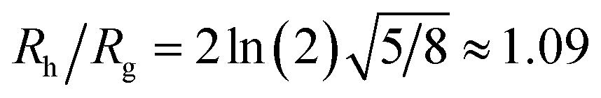 . We see that increasing the radius of the grafted sphere, and thus anisotropy of the dumbbell, causes a decrease in Rh/Rg, although Rh/Rg exhibits an unexpected shallow maximum when the attached sphere has a radius of about 0.3 times the radius of the “core” particle. This overshooting of the hard sphere value of the ratio Rh/Rg has been observed in simulations of high generation dendrimers under good solvent conditions where the strong repulsive interchain excluded volume interactions within these densely branched molecules cause leads to formation of distinct domains within the molecule and to an associated “crenulated” surface morphology.38 The most probable configurations of linear and branched polymer chains under equilibrium conditions are rather anisotropic, and corresponding Rh/Rg is normally significantly less than 1.64 The density profile of the polymer or particle can also impact this ratio and measurements of Rh and Rg of polymer grafted NPs are instructive in illustrating this effect, as we now describe. There are some complications with such measurements that need to be described first, however.
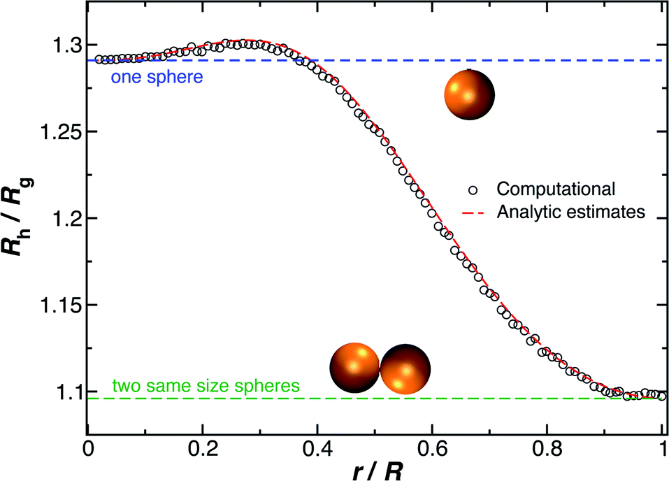 | ||
| Fig. 16 The hydrodynamic radius Rh normalized by the radius of gyration Rg for a dumbbell as a function of the ratio (r/R). The solid symbols are calculations and the analytic results (dashed lines with ρ = 0.98) are obtained by combining eqn (6) with eqn (15). | ||
Although a combination of static and dynamic scattering measurements can be highly revealing about the nature of the grafted polymer layer on NPs, it must be remembered that scattering measurements often depend on scattering contrast, which can complicate this type of analysis. For example, the estimation of Rg by X-rays is normally dominated by the scattering of the metal core of the NP, making the grafted layer nearly “invisible”. By deuterating the polymer chains, the neutron scattering of this type of particles can be dominated by the grafted chains and the metal nanoparticle can be made to be effectively “invisible” by appropriate contrast matching. For nanoparticles composed of the same chemical species, the entire particle has essentially the same contrast, which is another type of “soft” NP commonly encountered in applications. Fig. 17 shows Rh/Rg based on these different experimental methods. In this figure, the black line shows the case where all contrast comes from the NP core and the blue line indicates an ideal neutron measurement estimate of Rh/Rg where all scattering contrast for Rg is derived from the polymer grafted chains. The uniform scattering case, appropriate for NPs having a uniform chemistry, is shown as the red curve in Fig. 17. The ratio Rh/Rg rises with surfaces coverage and peaks near the saturation coverage ≈50 grafted strands for this NP. The neutron estimates of Rg, in combination with Rh measurements, also seem to provide an effective methodology for identification of the formation of a “saturated” grafted layer. Note that Rh/Rg significantly exceeds the value for a spherical particle, Rh/Rg = 1.29 for the uniform contrast case, where the excess value provides valuable information about the diffuse grafted polymer layer. Values of Rh/Rg corresponding to the equal contrast estimates in Fig. 17 have often been reported in microgel NPs.32,33 Values of Rh/Rg significantly larger than the hard sphere value have also been observed polyelectrolyte complexes of DNA and polyethyleneamine41 of interest in gene therapy and antiviral medicines.118 In these systems, the DNA forms a dense core structure analogous to the metal nanoparticle in the present paper and the polyethylene molecules form a diffuse peripheral layer structurally analogous to the grafted ssDNA layer. We may also the presence of the spike proteins on COVID virus and other spherical viruses with spike like structures on their surfaces to lead to especially large values of Rh/Rg. We find that this ratio can become as large as Rh/Rg = 2.14, when the grafted polymers are assumed to adopt a rod-like conformation when N is large. Hydrodynamically, these particles behave as if they are much larger than their spherical core, an effect that we term the “dandelion effect”.
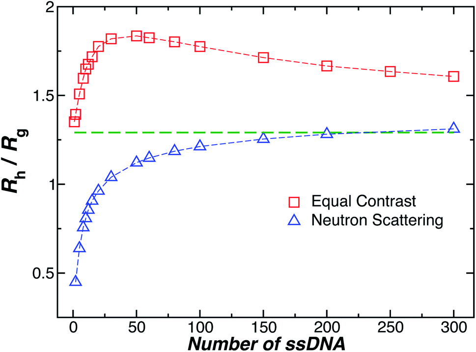 | ||
| Fig. 17 The hydrodynamic radius Rh normalized by the radius of gyration Rg for a 5 nm in radius NP decorated with different number of strands having each strands 18 T bases. Dashed lines guide the eye. | ||
4.2 Intrinsic viscosity
Although Rh and Rg are the primary measures of NP size utilized in their solution characterization, [η] and second osmotic virial coefficient A2 are often utilized to characterize polymers in solution119,120 and we may expect these solution properties to also become important in the characterization of NPs in the future. Here, [η] is defined as,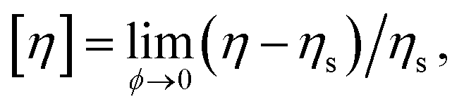 | (16) |
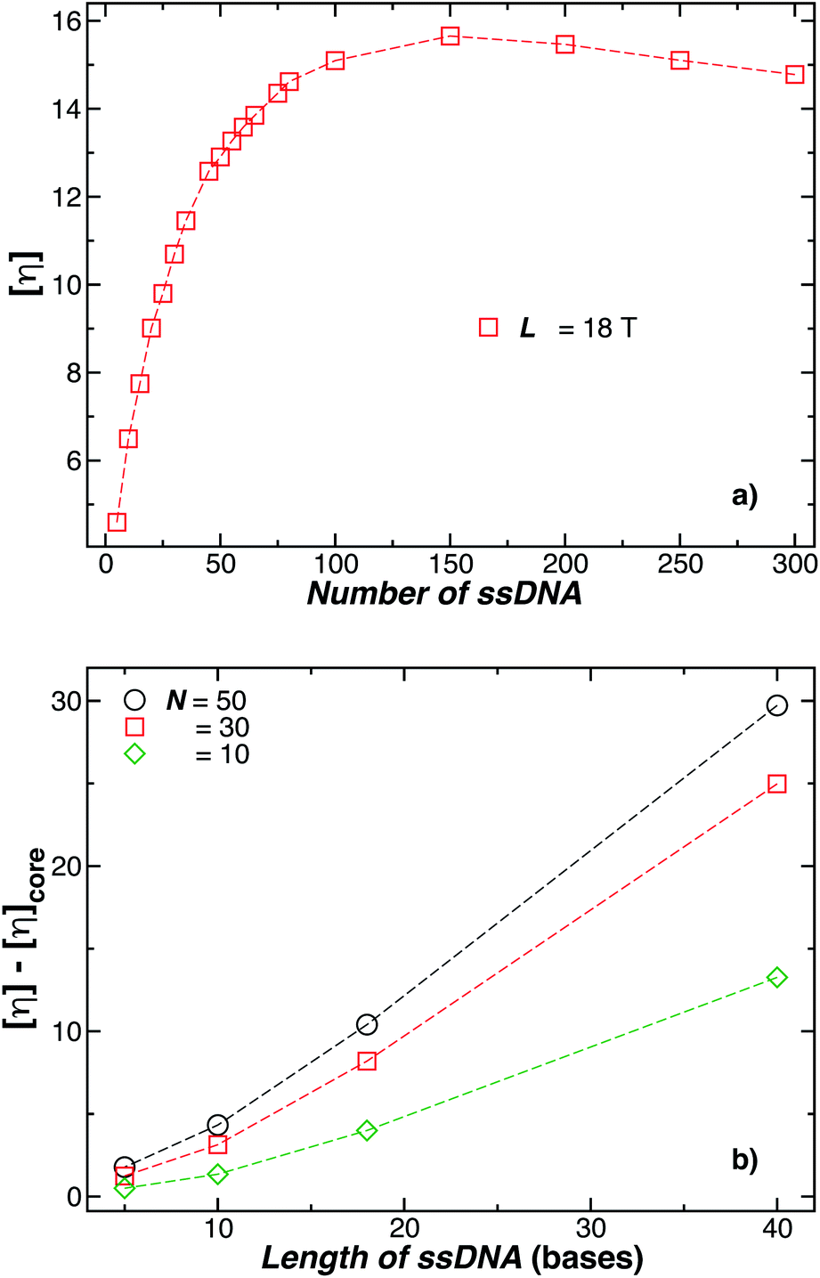 | ||
| Fig. 18 In (a) the intrinsic viscosity [η] for a 5 nm in radius NP decorated with different number of strands having each strand 18 T bases. Evidently, [η] reaches its maximum value when N ≈ 150 chains, but [η] must approach the Einstein value 5/2 in the dense “brush limit” when the grafting density becomes uniform. (b) Enhancement of [η] for the polymer-grafted NPs as a function of the chain length. The number of chains attached on each NP is reported in the legend. Dashed lines guide the eye. | ||
It is evident that the common procedure,122–125 of determining the “effective volume fraction” ϕ of suspensions by matching the linear concentration dependence of the solution viscosity to the Einstein result, [η] = 2.5 can be problematic when the particles have diffuse interfacial layers, as often found for grafted NPs and “soft” NPs. It is then quite understandable why the apparent volume fraction is often reported to be much larger than 1.125 We suggest this procedure of volume fraction estimation should be avoided and solution properties based on a dubious “mapping” onto hard sphere suspensions should be replaced using the reduced concentration variable, [η]ϕ.
5 Conclusions
We have developed series of models of increasing molecular faithfulness of individual polymer chains grafted onto a spherical nanoparticle (NP) structure (spheres, ellipsoids, semi-flexible polymer chains with excluded volume interactions), and we then extended the model to describe collections of these coarse-grained model polymers using a combination of molecular dynamics simulations of the conformational structure of the grafted polymer layers and the path-integration program ZENO43 to calculate basic solution hydrodynamic properties, hydrodynamic radius (Rh), radius of gyration (Rg), and intrinsic viscosity ([η]). We particularly emphasize Rh calculations because these measurements have been found to be especially useful in applications aimed at characterizing these NPs in relation to biophysical activity in many emerging applications using this type of NP for drug delivery, diagnostics, and other medical applications, and in connection with assessing the toxicity of NPs released into the environment, as summarized in our introduction. The potential applications are made broader by the fact that when NPs are released into the environment, they tend to spontaneously acquire a grafted layer or “corona” layer on their surfaces (auto-grafting) arising from the physical binding of polymers in their environment to the NPs and our modeling methodology can be used also for modeling such systems under thermodynamic conditions where the molecular binding to the “bare” NPs can be described by a reversible reaction process.We have found that the presence of the grafted layer can greatly alter the “effective size” of the inorganic NPs to which they are grafted, even when the polymer grafting density is relatively low. Moreover, the average hydrodynamic thickness, of this grafted layer, and fluctuations in its effective thickness and correspondingly the NP hydrodynamic size, are also highly dependent on the length of the grafted chains and grafting density, the strength of the interaction potential between the polymers and the surface of the core NP, and the size of the NP core relative to the radius of gyration of the grafted polymer chains. The strong hydrodynamic screening effect88 within the diffuse grafted polymer layer then allows us to understand the relatively large values (significantly larger that the ratio of hard sphere particles) of the ratio Rh/Rg observed in polymer grafted NPs, and other soft gel particle systems such microgel particles. Intrinsic viscosity derived measures of hydrodynamic size can be likewise expected to be “anomalously large”, but we do not emphasize these measurements because of their more limited use in NP characterization.
Our results for the solution size ratio Rh/Rg of polymer grafted NPs are contrasted with those for isolated linear polymers, and even polymers having regular branched architectures such as star and ring polymers, where Rh/Rg is generally less than the value for hard spheres, often taking significantly smaller values30,50 The extent of this hydrodynamic “screening effect”88 depends on the polymer grafting density and polymer chain length, and we also investigate the distribution and variance of these solution properties that arise from fluctuations in the conformation of the grafted chains, as well as the positions of grafting on the supporting sphere. Fluctuations in the grafted layer structure can be expected to alter the interaction between these complex NPs and with biomacromolecules of relevance to their medical applications.
We then expect this computational methodology, in conjunction of experimental measurements, should be useful for characterizing polymer-grafted NPs for use in many applications in material science and nanomedicine and in needed studies aimed at evaluating the environmental impact of NPs in the environment. Although we have combined our applications to spherical core particles with grafted single stranded DNA layers, the ZENO methodology, in conjunction with molecular dynamics simulation, allows for the treatment of NPs having essentially arbitrary shape and polymer monomer structure and having variable molecular rigidity and local intermolecular potential interactions. Previous attempts at describing polymer grafted NPs have generally been based on heuristic “layer models” that do not consider hydrodynamic interaction effects arising between the molecules in the grafted layer and the NP to which they are grafted or between the chains in the layer nor the effect of fluctuations in the overall thickness and shape of the grafted layer that arise in conformational fluctuations of the polymer chains in the layer or chain conformational fluctuations. In contrast, our computational method, should enable the quantification of these fluctuation effects through appropriately designed simulations and measurements.
As a final point, we emphasize that the present work has emphasized the characterization of individual DNA grafted Au nanoparticles based on solution properties performed at high dilution such as the hydrodynamic radius and intrinsic viscosity. Many applications of polymer grafted nanoparticles, on the other hand, involve higher NP concentrations where such nanoparticles start clustering, leading to evident changes in the optical properties of these solutions15,126,127 that are useful in colorimetric sensing applications, etc. The effects of nanoparticle association, such as dimer formation,128–130 is clearly discernible experimentally. Dimerization of DNA grafted nanoparticles has been modeled by the same coarse-grained model as utilized in the present paper26,27,46 and it would be a relatively simple matter to calculate the size distribution of the hydrodynamic radius of these dimers under different conditions to compare with dynamic light scattering and high resolution sedimentation coefficient measurements of these dimers based on simulations of the kind described in the present paper. Very interesting measurements have been performed showing the change in the hydrodynamic radius of DNA grafted nanoparticles when complementary linear chains are physically bound to the grafted chains.131,132 Under more general circumstances, the binding of molecules on drug end-functionalized grafted polymers on nanoparticles could be modeled to determine the degree of this binding to the grafted nanoparticle. This type of information would obviously be useful in many biomedical applications. There has also been great interest in creating and controlling larger clusters of DNA grafted nanoparticles and even crystalline arrays of nanoparticles.25,29,133–136 Sheets or “membranes” of DNA grafted nanoparticles have also been synthesized.137 There is thus considerable scope for extending the present to seemingly endless configurations of DNA grafted nanoparticle that can be created with these inherently modular materials.
Conflicts of interest
We report no known conflict of interest.Acknowledgements
This work was supported by NIST awards 70NANB13H202 and 70NANB15H282.Notes and references
- R. Sperling and W. Parak, Philos. Trans. R. Soc., A, 2010, 368, 1333–1383 CrossRef CAS.
- F. Nicolson, A. Ali, M. Kircher and S. Pal, Adv. Sci., 2020, 7(23), 2001669 CrossRef CAS PubMed.
- P. P. P. Kumar and D.-K. Lim, Pharmaceutics, 2022, 14(1), 70 CrossRef CAS PubMed.
- J. D. Gibson, B. P. Khanal and E. R. Zubarev, J. Am. Chem. Soc., 2007, 129, 11653–11661 CrossRef CAS PubMed.
- S. D. Brown, P. Nativo, J.-A. Smith, D. Stirling, P. R. Edwards, B. Venugopal, D. J. Flint, J. A. Plumb, D. Graham and N. J. Wheate, J. Am. Chem. Soc., 2010, 132, 4678–4684 CrossRef CAS PubMed.
- R. Petros and J. DeSimone, Nat. Rev. Drug Discovery, 2010, 9, 615–627 CrossRef CAS PubMed.
- d. n. Heo, D. H. Yang, H.-J. Moon, J. Lee, M. S. Bae, S. Lee, W. Lee, I.-C. Sun and I. K. Kwon, Biomaterials, 2012, 33, 856–866 CrossRef CAS.
- P. Singh, S. Pandit, V. Mokkapati, A. Garg, V. Ravikumar and I. Mijakovic, Int. J. Mol. Sci., 2018, 19(7), 1979 CrossRef PubMed.
- A. Ghasemi, N. Rabiee, S. Ahmadi, S. Hashemzadeh, F. Lolasi, M. Bozorgomid, A. Kalbasi, B. Nasseri, A. Shiralizadeh Dezfuli, A. Aref, M. Karimi and M. Hamblin, Analyst, 2018, 143, 3249–3283 RSC.
- M. S. Draz and H. Shafiee, Theranostics, 2018, 8, 1985–2017 CrossRef CAS PubMed.
- D. Liu, Z. Wang and X. Jiang, Nanoscale, 2011, 3, 1421–1433 RSC.
- J. Du, L. Jiang, Q. Shao, X. Liu, R. S. Marks, J. Ma and X. Chen, Small, 2013, 9, 1467–1481 CrossRef CAS PubMed.
- Z. He, H. Yin, C.-C. Chang, G. Wang and X. Liang, Biosensors, 2020, 10(11), 167 CrossRef CAS PubMed.
- J. Huang, Y. Zhang, Z. Lin, W. Liu, X. Chen, Y. Liu, H. Tian, Q. Liu, R. Gillibert, J. Spadavecchia, N. Djaker, M. L. de la Chapelle, Y. Xiang and W. Fu, Nanophotonics, 2019, 8, 1495–1503 CAS.
- R. Elghanian, J. J. Storhoff, R. C. Mucic, R. L. Letsinger and C. A. Mirkin, Science, 1997, 277, 1078–1081 CrossRef CAS PubMed.
- L. Dykman and N. Khlebtsov, Chem. Soc. Rev., 2012, 41, 2256–2282 RSC.
- T. Pylaev, E. Avdeeva and N. Khlebtsov, J. Innovative Opt. Health Sci., 2021, 14, 2130003 CrossRef CAS.
- S. A. Bansal, V. Kumar, J. Karimi, A. P. Singh and S. Kumar, Nanoscale Adv., 2020, 2, 3764–3787 RSC.
- H. Zhang, N. S. Goh, J. W. Wang, R. L. Pinals, E. González-Grandío, G. S. Demirer, S. Butrus, S. C. Fakra, A. Del Rio Flores and R. Zhai, et al., Nat. Nanotechnol., 2022, 17, 197–205 CrossRef CAS PubMed.
- J. M. Buriak, L. M. Liz-Marzán, W. J. Parak and X. Chen, ACS Nano, 2022, 16, 1681–1684 CrossRef CAS.
- M. M. Maye, D. Nykypanchuk, D. Van Der Lelie and O. Gang, Small, 2007, 3, 1678–1682 CrossRef CAS PubMed.
- K. Saha, S. S. Agasti, C. Kim, X. Li and V. M. Rotello, Chem. Rev., 2012, 112, 2739–2779 CrossRef CAS PubMed.
- C. Mirkin, Spherical Nucleic Acids, Jenny Stanford Publishing, NY, 2020 Search PubMed.
- J. Chao, Y. Lin, H. Liu, L. Wang and C. Fan, Mater. Today, 2015, 18, 326–335 CrossRef CAS.
- W. Liu, M. Tagawa, H. L. Xin, T. Wang, H. Emamy, H. Li, K. G. Yager, F. W. Starr, A. V. Tkachenko and O. Gang, Science, 2016, 351, 582–586 CrossRef CAS PubMed.
- F. Vargas-Lara and F. W. Starr, Soft Matter, 2011, 7, 2085–2093 RSC.
- O. Padovan-Merhar, F. Vargas-Lara and F. W. Starr, J. Chem. Phys., 2011, 134, 244701 CrossRef PubMed.
- P. J. Santos, Z. Cao, J. Zhang, A. Alexander-Katz and R. J. Macfarlane, J. Am. Chem. Soc., 2019, 141, 14624–14632 CrossRef CAS PubMed.
- P. Santos, P. Gabrys, L. Zornberg, M. Lee and R. Macfarlane, Nature, 2021, 591, 586–591 CrossRef CAS PubMed.
- F. Vargas-Lara, B. A. Pazmino Betancourt and J. F. Douglas, J. Chem. Phys., 2018, 149, 161101 CrossRef.
- M. Xu, M. G. Soliman, X. Sun, B. Pelaz, N. Feliu, W. J. Parak and S. Liu, ACS Nano, 2018, 12, 10104–10113 CrossRef CAS PubMed.
- M. Schmidt, D. Nerger and W. Burchard, Polymer, 1979, 20, 582–588 CrossRef CAS.
- M. Antonietti, W. Bremser and M. Schmidt, Macromolecules, 1990, 23, 3796–3805 CrossRef CAS.
- I. Varga, T. Gilanyi, R. Meszaros, G. Filipcsei and M. Zrinyi, J. Phys. Chem. B, 2001, 105, 9071–9076 CrossRef CAS.
- D. W. Holley, M. Ruppel, J. W. Mays, V. S. Urban and D. Baskaran, Polymer, 2014, 55, 58–65 CrossRef CAS.
- S. Rostom and M. D. Dadmun, J. Appl. Phys., 2020, 127, 074303 CrossRef CAS.
- M. Mansfield and J. Douglas, Condens. Matter Phys., 2002, 30, 249–274 CrossRef CAS.
- B. A. P. Betancourt and J. F. Douglas, AIP Conf. Proc., 2016, 1736, 020077 CrossRef.
- C. Wu and S. Zhou, Phys. Rev. Lett., 1996, 77, 3053 CrossRef CAS PubMed.
- C. Wu and X. Wang, Phys. Rev. Lett., 1998, 80, 4092 CrossRef CAS.
- Z. Dai and C. Wu, Macromolecules, 2012, 45, 4346–4353 CrossRef CAS.
- J. B. Falabella, T. J. Cho, D. C. Ripple, V. A. Hackley and M. J. Tarlov, Langmuir, 2010, 26, 12740–12747 CrossRef CAS PubMed.
- M. Mansfield and J. Douglas, Phys. Rev. E: Stat., Nonlinear, Soft Matter Phys., 2008, 78, 046712 CrossRef PubMed.
- S. H. Ko, F. Vargas-Lara, P. N. Patrone, S. M. Stavis, F. W. Starr, J. F. Douglas and J. A. Liddle, Soft Matter, 2014, 10, 7370–7378 RSC.
- K. Kremer and G. S. Grest, J. Chem. Phys., 1990, 92, 5057–5086 CrossRef CAS.
- C. Chi, F. Vargas-Lara, A. V. Tkachenko, F. W. Starr and O. Gang, ACS Nano, 2012, 6, 6793–6802 CrossRef CAS.
- K. Venta, G. Shemer, M. Puster, J. A. Rodríguez-Manzo, A. Balan, J. K. Rosenstein, K. Shepard and M. Drndić, ACS Nano, 2013, 7, 4629–4636 CrossRef CAS PubMed.
- A. Y. L. Sim, J. Lipfert, D. Herschlag and S. Doniach, Phys. Rev. E: Stat., Nonlinear, Soft Matter Phys., 2012, 86, 021901 CrossRef PubMed.
- F. Vargas-Lara, F. W. Starr and J. F. Douglas, Soft Matter, 2017, 13, 8309–8330 RSC.
- F. Vargas-Lara, A. Hassan, M. Mansfield and J. Douglas, Sci. Rep., 2017, 7, 13374 CrossRef PubMed.
- S. Nosé, J. Chem. Phys., 1984, 81, 511–519 CrossRef.
- W. G. Hoover, Phys. Rev. A, 1985, 31, 1695–1697 CrossRef PubMed.
- S. Plimpton, J. Comput. Phys., 1995, 117, 1–19 CrossRef CAS.
- W. Humphrey, A. Dalke and K. Schulten, J. Mol. Graphics, 1996, 14, 33–38 CrossRef CAS.
- L. M. Demers, C. A. Mirkin, R. C. Mucic, R. A. Reynolds, R. L. Letsinger, R. Elghanian and G. Viswanadham, Anal. Chem., 2000, 72, 5535–5541 CrossRef CAS PubMed.
- S. J. Hurst, A. K. R. Lytton-Jean and C. A. Mirkin, Anal. Chem., 2006, 78, 8313–8318 CrossRef CAS PubMed.
- C. Li, J. Han, C. Y. Ryu and B. C. Benicewicz, Macromolecules, 2006, 39, 3175–3183 CrossRef CAS.
- Z. Wang, T. Liu, Y. Zhao, J. Lee, Q. Wei, J. Yan, S. Li, M. Olszewski, R. Yin and Y. Zhai, et al., Macromolecules, 2019, 52, 9466–9475 CrossRef CAS.
- P. Akcora, H. Liu, S. Kumar, J. Moll, Y. Li, B. Benicewicz, L. Schadler, D. Acehan, A. Panagiotopoulos, V. Pryamitsyn, V. Ganesan, J. Ilavsky, P. Thiyagarajan, R. Colby and J. Douglas, Nat. Mater., 2009, 8, 354–359 CrossRef CAS PubMed.
- I. Kohli, S. Alam, B. Patel and A. Mukhopadhyay, Appl. Phys. Lett., 2013, 102, 203705 CrossRef.
- P. Rothemund, Nature, 2006, 440, 297–302 CrossRef CAS PubMed.
- H. Jun, X. Wang, M. F. Parsons, W. P. Bricker, T. John, S. Li, S. Jackson, W. Chiu and M. Bathe, Nucleic Acids Res., 2021, 49, 10265–10274 CrossRef CAS PubMed.
- E. Poppleton, R. Romero, A. Mallya, L. Rovigatti and P. Sulc, Nucleic Acids Res., 2021, 49, W491–W498 CrossRef CAS PubMed.
- M. L. Mansfield and J. F. Douglas, J. Chem. Phys., 2013, 139, 044901 CrossRef PubMed.
- M. L. Mansfield, A. Tsortos and J. F. Douglas, J. Chem. Phys., 2015, 143, 124903 CrossRef.
- D. Bedrov, G. D. Smith and L. Li, Langmuir, 2005, 21, 5251–5255 CrossRef CAS PubMed.
- J. B. Hooper, D. Bedrov and G. D. Smith, Langmuir, 2008, 24, 4550–4557 CrossRef CAS PubMed.
- A. Karim, V. Tsukruk, J. Douglas, S. Satija, L. Fetters, D. Reneker and M. Foster, J. Phys. II, 1995, 5, 1441–1456 CrossRef CAS.
- J. F. Douglas, H. E. Johnson and S. Granick, Science, 1993, 262, 2010–2012 CrossRef CAS PubMed.
- H. E. Johnson, J. F. Douglas and S. Granick, Phys. Rev. Lett., 1993, 70, 3267–3270 CrossRef CAS.
- K. M. Koo, A. A. I. Sina, L. G. Carrascosa, M. J. A. Shiddiky and M. Trau, Anal. Methods, 2015, 7, 7042–7054 RSC.
- D. Y. Petrovykh, V. Perez-Dieste, A. Opdahl, H. Kimura-Suda, J. M. Sullivan, M. J. Tarlov, F. J. Himpsel and L. J. Whitman, J. Am. Chem. Soc., 2006, 128, 2–3 CrossRef CAS PubMed.
- J. Yang, J. Y. Lee, H.-P. Too, G.-M. Chow and L. M. Gan, Chem. Phys., 2006, 323, 304–312 CrossRef CAS.
- S. H. D. P. Lacerda, J. J. Park, C. Meuse, D. Pristinski, M. L. Becker, A. Karim and J. F. Douglas, ACS Nano, 2010, 4, 365–379 CrossRef PubMed.
- A. Karim, S. Satija, J. Douglas, J. Ankner and L. Fetters, Phys. Rev. Lett., 1994, 73, 3407 CrossRef CAS PubMed.
- M. D. Whitmore, G. S. Grest, J. F. Douglas, M. S. Kent and T. Suo, J. Chem. Phys., 2016, 145, 174904 CrossRef PubMed.
- D. Bracha, E. Karzbrun, G. Shemer, P. A. Pincus and R. H. Bar-Ziv, Proc. Natl. Acad. Sci. U. S. A., 2013, 110, 4534–4538 CrossRef CAS.
- P. Gallagher, S. Satija, A. Karim, J. Douglas and L. Fetters, J. Polym. Sci., Part B: Polym. Phys., 2004, 42, 4126–4131 CrossRef CAS.
- J. J. Park, S. H. D. P. Lacerda, S. K. Stanley, B. M. Vogel, S. Kim, J. F. Douglas, D. Raghavan and A. Karim, Langmuir, 2009, 25, 443–450 CrossRef CAS PubMed.
- E. M. Nelson and L. J. Rothberg, Langmuir, 2011, 27, 1770–1777 CrossRef CAS PubMed.
- W. J. Parak, T. Pellegrino, C. M. Micheel, D. Gerion, S. C. Williams and A. P. Alivisatos, Nano Lett., 2003, 3, 33–36 CrossRef CAS.
- A. Russell, Proc. Phys. Soc. London, 1924, 37, 282 CrossRef.
- J. B. Hubbard and J. F. Douglas, Phys. Rev. E: Stat. Phys., Plasmas, Fluids, Relat. Interdiscip. Top., 1993, 47, R2983–R2986 CrossRef CAS PubMed.
- E. Swanson, D. C. Teller and C. de Haen, J. Chem. Phys., 1980, 72, 1623–1628 CrossRef CAS.
- J. F. Douglas, H.-X. Zhou and J. B. Hubbard, Phys. Rev. E: Stat. Phys., Plasmas, Fluids, Relat. Interdiscip. Top., 1994, 49, 5319–5331 CrossRef PubMed.
- J. F. Douglas and K. F. Freed, Macromolecules, 1994, 27, 6088–6099 CrossRef CAS.
- H.-X. Zhou, A. Szabo, J. F. Douglas and J. B. Hubbard, J. Chem. Phys., 1994, 100, 3821–3826 CrossRef CAS.
- F. Vargas-Lara and J. F. Douglas, Soft Matter, 2015, 11, 4888–4898 RSC.
- F. Vargas-Lara, S. M. Stavis, E. A. Strychalski, B. J. Nablo, J. Geist, F. W. Starr and J. F. Douglas, Soft Matter, 2015, 11, 8273–8284 RSC.
- K. Solc, J. Chem. Phys., 1971, 55, 335–344 CrossRef CAS.
- C. Haber, S. A. Ruiz and D. Wirtz, Proc. Natl. Acad. Sci. U. S. A., 2000, 97, 10792–10795 CrossRef CAS PubMed.
- A. E. Cohen and W. Moerner, Proc. Natl. Acad. Sci. U. S. A., 2007, 104, 12622–12627 CrossRef CAS PubMed.
- A. Chremos and J. F. Douglas, J. Chem. Phys., 2015, 143, 111104 CrossRef PubMed.
- F. Vargas-Lara, M. L. Mansfield and J. F. Douglas, J. Chem. Phys., 2017, 147, 014903 CrossRef PubMed.
- T. Cedervall, I. Lynch, S. Lindman, T. Berggård, E. Thulin, H. Nilsson, K. A. Dawson and S. Linse, Proc. Natl. Acad. Sci. U. S. A., 2007, 104, 2050–2055 CrossRef CAS PubMed.
- S. Tenzer, D. Docter, S. Rosfa, A. Wlodarski, J. Kuharev, A. Rekik, S. K. Knauer, C. Bantz, T. Nawroth and C. Bier, et al., ACS Nano, 2011, 5, 7155–7167 CrossRef CAS PubMed.
- I. Lynch and K. Dawson, Nano Today, 2008, 3, 40–47 CrossRef CAS.
- Y. Pan, S. Neuss, A. Leifert, M. Fischler, F. Wen, U. Simon, G. Schmid, W. Brandau and W. Jahnen-Dechent, Small, 2007, 3, 1941–1949 CrossRef CAS PubMed.
- A. Nel, T. Xia, L. Madler and N. Li, science, 2006, 311, 622–627 CrossRef CAS PubMed.
- M. Lundqvist, J. Stigler, G. Elia, I. Lynch, T. Cedervall and K. A. Dawson, Proc. Natl. Acad. Sci. U. S. A., 2008, 105, 14265–14270 CrossRef CAS.
- M. P. Monopoli, C. Åberg, A. Salvati and K. A. Dawson, Nat. Nanotechnol., 2012, 7, 779–786 CrossRef CAS PubMed.
- W. Jiang, B. Y. Kim, J. T. Rutka and W. C. Chan, Nat. Nanotechnol., 2008, 3, 145–150 CrossRef CAS.
- L. Shang, K. Nienhaus and G. Nienhaus, J. Nanobiotechnol., 2014, 12, 5 CrossRef PubMed.
- C. Dong and J. Irudayaraj, J. Phys. Chem. B, 2012, 116, 12125–12132 CrossRef CAS PubMed.
- C. Rocker, M. Potzl, F. Zhang, W. Parak and G. Nienhaus, Nat. Nanotechnol., 2009, 4, 577–580 CrossRef PubMed.
- H. Wang, L. Shang, P. Maffre, S. Hohmann, F. Kirschhofer, G. Brenner-Weiß and G. U. Nienhaus, Small, 2016, 12, 5836–5844 CrossRef CAS PubMed.
- H. Moustaoui, J. Saber, I. Djeddi, Q. Liu, D. Movia, A. Prina-Mello, J. Spadavecchia, M. L. de la Chapelle and N. Djaker, Nanoscale, 2019, 11, 3665–3673 RSC.
- K. Nienhaus and G. Nienhaus, Biointerphases, 2020, 15, 061201 CrossRef CAS PubMed.
- J. Dudowicz, J. F. Douglas and K. F. Freed, J. Chem. Phys., 2019, 151, 124709 CrossRef PubMed.
- J. Dudowicz, J. F. Douglas and K. F. Freed, J. Chem. Phys., 2019, 151, 124706 CrossRef PubMed.
- H. Jans, X. Liu, L. Austin, G. Maes and Q. Huo, Anal. Chem., 2009, 81, 9425–9432 CrossRef CAS PubMed.
- J. F. Douglas, H. M. Schneider, P. Frantz, R. Lipman and S. Granick, J. Phys.: Condens. Matter, 1997, 9, 7699 CrossRef CAS.
- J. G. Kirkwood and J. Riseman, J. Phys. Chem., 1948, 16, 565–573 CrossRef CAS.
- J. Riseman and J. G. Kirkwood, J. Chem. Phys., 1949, 17, 442–446 CrossRef CAS.
- S.-Q. Wang, J. F. Douglas and K. F. Freed, J. Chem. Phys., 1986, 85, 3674–3687 CrossRef CAS.
- S. Wang, J. F. Douglas and K. F. Freed, J. Chem. Phys., 1987, 87, 1346–1354 CrossRef CAS.
- P. J. Wyatt, Anal. Chem., 2014, 86, 7171–7183 CrossRef CAS.
- O. Lőrincz, E. R. Tőke, E. Somogyi, F. Horkay, P. L. Chandran, J. F. Douglas, J. Szebeni and J. Lisziewicz, Nanomedicine, 2012, 8, 497–506 CrossRef.
- H. Yamakawa, Modern Theory of Polymer Solutions, Harper and Row, NY, 1971 Search PubMed.
- K. F. Freed, Renormalization Group Theory of Macromolecules, Wiley, NY, 1987 Search PubMed.
- A. Einstein, Ann. Phys., 1911, 34, 591–592 CrossRef CAS.
- H. Senff and W. Richtering, Colloid Polym. Sci., 2000, 278, 830–840 CrossRef CAS.
- J. Mattsson, H. Wyss, A. Fernandez-Nieves, K. Miyazaki, Z. Hu, D. Reichman and D. Weitz, Nature, 2009, 462, 83–86 CrossRef CAS PubMed.
- S. Franco, E. Buratti, B. Ruzicka, V. Nigro, N. Zoratto, P. Matricardi, E. Zaccarelli and R. Angelini, J. Phys.: Condens. Matter, 2021, 33(17), 174004 CrossRef CAS PubMed.
- K. Van der Vaart, Y. Rahmani, R. Zargar, Z. Hu, D. Bonn and P. Schall, J. Rheol., 2013, 57, 1195–1209 CrossRef CAS.
- R. A. Reynolds, C. A. Mirkin and R. L. Letsinger, J. Am. Chem. Soc., 2000, 122, 3795–3796 CrossRef CAS.
- J. J. Storhoff, A. A. Lazarides, R. C. Mucic, C. A. Mirkin, R. L. Letsinger and G. C. Schatz, J. Am. Chem. Soc., 2000, 122, 4640–4650 CrossRef CAS.
- M. P. Busson, B. Rolly, B. Stout, N. Bonod, E. Larquet, A. Polman and S. Bidault, Nano Lett., 2011, 11, 5060–5065 CrossRef CAS.
- L. Lermusiaux, A. Sereda, B. Portier, E. Larquet and S. Bidault, ACS Nano, 2012, 6, 10992–10998 CrossRef CAS.
- L. Lermusiaux and S. Bidault, Langmuir, 2018, 34, 14946–14953 CrossRef CAS PubMed.
- J. Xu and S. L. Craig, J. Am. Chem. Soc., 2005, 127, 13227–13231 CrossRef CAS PubMed.
- J. Xu and S. L. Craig, Langmuir, 2007, 23, 2015–2020 CrossRef CAS PubMed.
- W. Liu, J. Halverson, Y. Tian, A. V. Tkachenko and O. Gang, Nat. Chem., 2016, 8, 867–873 CrossRef CAS PubMed.
- H. Emamy, O. Gang and F. W. Starr, Nanomaterials, 2019, 9, 661 CrossRef CAS.
- P. W. Majewski, A. Michelson, M. A. Cordeiro, C. Tian, C. Ma, K. Kisslinger, Y. Tian, W. Liu, E. A. Stach and K. G. Yager, et al., Sci. Adv., 2021, 7, eabf0617 CrossRef CAS PubMed.
- Y. Tian, J. R. Lhermitte, L. Bai, T. Vo, H. L. Xin, H. Li, R. Li, M. Fukuto, K. G. Yager and J. S. Kahn, et al., Nat. Mater., 2020, 19, 789–796 CrossRef CAS PubMed.
- N. Geerts and E. Eiser, Soft Matter, 2010, 6, 664–669 RSC.
| This journal is © The Royal Society of Chemistry 2022 |