 Open Access Article
Design of self-assembling mesoscopic Goldberg polyhedra†
Istvan
Horvath
 ab,
David J.
Wales
 *c and
Szilard N.
Fejer
 *ab
*ab
aProvitam Foundation, Caisului Street 16, Cluj-Napoca, Romania. E-mail: szilard.fejer@cantab.net
bUniversity of Pécs, Institute of Chemistry, 6 Ifjúság Street, Pécs, Hungary
cDepartment of Chemistry, University of Cambridge, Lensfield Road, Cambridge CB2 1EW, UK. E-mail: dw34@cam.ac.uk
First published on 15th August 2022
Abstract
Palladium ions complexed with nonlinear bidentate ligands have been shown to form hollow, spherical shells with high symmetries. We show that such structures can be reproduced using model anisotropic mesoscale building blocks featuring excluded volume and long-range ionic interactions. A linear building block with a central charged particle, in combination with a bent ‘ligand’ particle with opposite charges at the ends is sufficient to drive the system towards planar coordination, and the charge ratio determines the coordination number. Similar to the molecular systems, the bend in the ‘ligand’ particle determines the curvature of the shells that these building blocks prefer. Besides reproducing exotic structures such as M30L60 and M48L96 tetravalent Goldberg polyhedra, we identify highly cooperative single transition state rearrangements between low-energy competing structures as well, corresponding to rotatory motions of a planar subunit within the spherical shell.
1. Introduction
A wide variety of hollow shells (container compounds) can now be synthesized through self-assembly, using mostly palladium(II) complexes with empty coordination sites, in combination with bidentate or tridentate ligands.1,2 In particular, MnL2n metal–ligand complexes have been synthesized and studied in great detail. Some of these complexes have the symmetry of Platonic or Archimedean solids (n = 6, 12, 24 and 30). Self-assembly of smaller clusters (n = 6, 12) has been simulated with coarse-grained molecular dynamics before,3–5 producing results in line with experimental observations. The symmetry of such spherical shells can be octahedral (n = 6, 12 and 24) or icosahedral (n = 30 and 60, although a shell with 60 metal ions has not yet been synthesised).Recently, a new class of larger shells has been discovered, which did not fit the symmetries of previously described MnL2n shells.6 In order to characterise these assemblies, Fujita et al. extended the description of classical Goldberg polyhedra,7 labelling the new class ‘tetravalent Goldberg’ polyhedral shells. Fujita et al. managed to synthesise such shells for n = 30 and 48. In these two shells, the metal ion is in square planar coordination with the bidentate ligands, and the metal ion frame of the shell is composed by 8 triangles and 24 or 42 squares, respectively.
The concept of ‘colloidal molecules’8–11 holds great promise in the design of novel functional materials. For example, by using patchy particles, it is possible to create ‘colloidal atoms’ with coordination numbers inaccessible in molecular systems. In this contribution, we design anisotropic colloidal building blocks capable of square planar coordination, with only electrostatic and excluded volume interactions between them. We are aiming for a model that also supports low-energy structures with tetravalent Goldberg symmetry, having a minimal number of interaction sites within each building block, while also keeping the interaction types to a minimum. In this way, we aim to elucidate the minimal conditions necessary for the assembly of such shells, and study the dynamics of rearrangements between competing structures.
2. The model
We consider a binary system with 1![[thin space (1/6-em)]](https://www.rsc.org/images/entities/char_2009.gif) :
:![[thin space (1/6-em)]](https://www.rsc.org/images/entities/char_2009.gif) 2 number ratio, analogous to the experimental MnL2n complexes. Our model building blocks have three interaction sites for both the M and L particles. In our model, distances, charges, energies and simulation times are specified in reduced units of d0, q0, ε0 and t0. Particle M is essentially a charged sphere (+4) with two identical axial sites attached to it, while particle L is V-shaped, the two ends being identical spheres with charge −1, and its central site is uncharged. We keep the distance between two C sites in one building block fixed at 3 distance units, to prevent two sites from the same building block binding to the same M particle. The ‘ligand’ particles will therefore act as bridges between two M building blocks. In this way we also define the minimum distance between two neighbouring M particles in a cluster, as they will be located at least 3 distance units apart, due to the size of the bridging L particle. The bend angle of the L particle is adjusted by displacing site D from the axis defined by the two charged sites (Fig. 1). Overall, there are only three distinct site types in the system (positively charged, negatively charged, and carrying no charge), coloured differently in Fig. 1. The 4
2 number ratio, analogous to the experimental MnL2n complexes. Our model building blocks have three interaction sites for both the M and L particles. In our model, distances, charges, energies and simulation times are specified in reduced units of d0, q0, ε0 and t0. Particle M is essentially a charged sphere (+4) with two identical axial sites attached to it, while particle L is V-shaped, the two ends being identical spheres with charge −1, and its central site is uncharged. We keep the distance between two C sites in one building block fixed at 3 distance units, to prevent two sites from the same building block binding to the same M particle. The ‘ligand’ particles will therefore act as bridges between two M building blocks. In this way we also define the minimum distance between two neighbouring M particles in a cluster, as they will be located at least 3 distance units apart, due to the size of the bridging L particle. The bend angle of the L particle is adjusted by displacing site D from the axis defined by the two charged sites (Fig. 1). Overall, there are only three distinct site types in the system (positively charged, negatively charged, and carrying no charge), coloured differently in Fig. 1. The 4![[thin space (1/6-em)]](https://www.rsc.org/images/entities/char_2009.gif) :
:![[thin space (1/6-em)]](https://www.rsc.org/images/entities/char_2009.gif) 1 charge ratio between the sites is important, not only to maintain the MnL2n clusters electrostatically neutral, but also to drive the M particles to bind to four L particles. Excluded volume interactions are modelled with repulsive r−12 terms. For simplicity, we do not use such terms for the interaction between two charged sites of the same type. The potential energy of a cluster with an arbitrary number of building blocks is therefore
1 charge ratio between the sites is important, not only to maintain the MnL2n clusters electrostatically neutral, but also to drive the M particles to bind to four L particles. Excluded volume interactions are modelled with repulsive r−12 terms. For simplicity, we do not use such terms for the interaction between two charged sites of the same type. The potential energy of a cluster with an arbitrary number of building blocks is therefore | (1) |
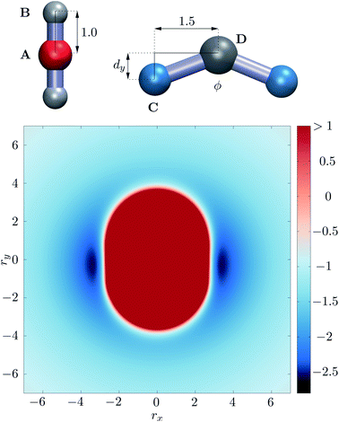 | ||
| Fig. 1 Top: Schematic representation of the M and L type building blocks, with the four different site types labelled. Sites B and D carry no charge, while A and C carry different charges of opposite sign. Bottom: potential energy surface for the building blocks in the relative orientation shown at the top, as a function of displacement in the x and y directions, while all sites are in the xy plane, and distance is measured between sites A and D. ESI Movie 1† shows how this potential energy surface changes with rotation of the L particle about its z axis centred on site D. | ||
| Site | A | B | C | D |
|---|---|---|---|---|
| A | — | 105 | 1 | 105 |
| B | 105 | 105 | 1 | 105 |
| C | 1 | 1 | — | 105 |
| D | 105 | 105 | 105 | 105 |
3. Results and Discussion
We determined two key conditions for such building blocks to assemble into hollow shells: the charge ratio between sites A and C sets the preferred coordination of the M particle, and the strength of the r−12 excluded volume interactions between sites C and sites of the M particle must be much smaller than that of all the other excluded volume interactions. The net effect is that the M particle attracts the charged sites of the L particles equatorially, as seen in Fig. 1.As we have shown before,13–15 it is not straightforward to define the shape of a rigid body particle that features anisotropic interactions. It is the combination of shape and interaction anisotropies that defines self-assembling properties for target structures. In the present case, the perceived ‘shape’ of the M particle by the L particle (and vice versa) is a spherocylinder with 4![[thin space (1/6-em)]](https://www.rsc.org/images/entities/char_2009.gif) :
:![[thin space (1/6-em)]](https://www.rsc.org/images/entities/char_2009.gif) 3 aspect ratio, shown in red in Fig. 1. This shape (the repulsive part of the potential energy surface) does not change much with the relative orientation of the two particles, as shown in ESI Movie 1,† only the attractive interaction strength varies significantly with the orientation.
3 aspect ratio, shown in red in Fig. 1. This shape (the repulsive part of the potential energy surface) does not change much with the relative orientation of the two particles, as shown in ESI Movie 1,† only the attractive interaction strength varies significantly with the orientation.
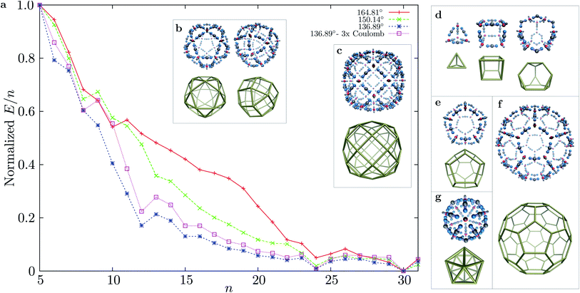
Using basin-hopping global optimisation16 adapted for rigid body building blocks,17,18 we determined the lowest energy structures for n = 1 to 31 for three bend angles of the ‘ligand’ particles in MnL2n clusters. The normalised E/n values for the global minima are shown in Fig. 2, for structures starting with n = 5. The E/n values were normalised to the energy interval defined by the largest and smallest E/n values for cluster sizes n = 5 to 31 for each parameterisation. All clusters with larger stabilisation than their neighbours are highly symmetric. For the smallest bend angle, three magic number clusters are observed, in accordance with the principle of maximum symmetry:19,20n = 12 (cuboctahedron), n = 24 (rhombicuboctahedron), and n = 30 (icosahedral symmetry). The character of the E/n vs. n plot does not change significantly when we consider a three times stronger coulombic interaction (εQ = 3). For the two larger bend angles, the curvature of the n = 12 shells is not as favourable, and the two magic numbers that are closed shells are n = 24 and 30. Although for n = 24 the symmetry of the global minimum is the same for all bend angles considered, the structure of the global minimum for n = 30 changes from icosahedral (136.39°, 150.14°) to a chiral tetravalent Goldberg polyhedron at the largest bend angle (164.81°), in which the M and L particles are arranged in the same way as the experimentally synthesised Pd(II) shells of Fujita et al. (right panel of Fig. 2b). For all three bend angles and the size range considered, n = 30 has the lowest energy per particle, and is the most stable size. The n = 24 cluster is progressively destabilised, compared to n = 30, as the bend angle increases (the preferred curvature is decreased).
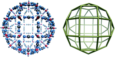
The complexity of the energy landscape increases exponentially with the cluster size,16,21 and it was therefore not possible to reliably locate the lowest energy structure for n = 48, the next size compatible with a tetravalent Goldberg structure, starting from random configurations. However, using a harmonic spherical constraint potential during basin-hopping steps greatly reduces the number of available configurations for the 144 rigid bodies, and the global minimum is then found to be analogous to the experimental system, although less spherical for this parameterisation, due to the stiffness of the square planar coordination. However, if we relax the stiffness by increasing the distance between the charged central site and one repulsive LJ site in the M particles, we obtain the spherical tetravalent Goldberg global minimum for n = 48, in which the elongated axial sites of the M particles point inwards (Fig. 3).
The framework presented above allows for the rational design of highly symmetric MnLm polyhedral shells, in which the vertices of the polyhedra are the M particles, and the L particles are situated along the edges. For small polyhedra (high curvature), the preferred curvature can be set either by using M particles with one fewer axial repulsive site, or highly bent L particles. Clearly, the charge ratio between the sites should be set according to the coordination number in these shells. Global optimisation of clusters with the appropriate number of M and L particles leads to a wide variety of global minima corresponding to symmetric shells: namely the tetrahedron, cube, truncated tetrahedron, dodecahedron, icosahedron, truncated icosahedron, as shown in Fig. 2d–g.
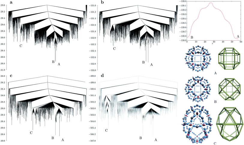
As the shell size increases, the curvature of the shell decreases accordingly, and with it the relative energy difference between other possible shell configurations becomes smaller. The ligand bend angle greatly influences the underlying self-assembling character of the potential energy landscape. We explored the landscapes using discrete path sampling22 for n = 24 and 30 for all three bend angles considered. Fig. 4 shows the disconnectivity graph23,24 for M24L48 with ligand bend angles of about 164°, 157° and 136°. In all cases, the energy difference between the rhombicuboctahedron and pseudorhombicuboctahedron is very small, compared to the rest of the landscape. For the smallest bend angle, the third lowest minimum is a prolate structure with D4d symmetry (labelled C in Fig. 4), in which the M particles are at the vertices of a polyhedron consisting of 8 triangles, 8 pentagons and 2 squares. The energy of such structures increases with increasing bend angle, but in all cases the D4d configuration produces a separate funnel on the landscape. If the coulombic interaction strength is increased (Fig. 4d), this funnel becomes even better separated from the rest of the landscape. From the D4d structure, the rhombicuboctahedral global minimum or the pseudorhombicuboctahedral kinetic trap can be accessed only through significantly higher barriers in this case.
A remarkable feature of the system shown in Fig. 4c is the mechanism through which the pseudorhombicuboctahedral and rhombicuboctahedral structures can interconvert. This process is a highly cooperative rearrangement via a single transition state with an almost symmetrical energy profile featuring two shoulders on both sides. The mechanism can be split into the following sequence of five distinct ‘swinging’ motions: a charged site of the L particle detaches from an M particle (first shoulder), the L particle moves towards the inside of the shell, swings over and attaches itself to the neighbouring M particle through the free charged site, while displacing another L particle at the opposite side of the M particle (second shoulder). The newly displaced L particle repeats the same motion, displacing another L particle, until the displaced particle attaches to an M particle with a free valence. The mechanism is shown in ESI Movie 2.† The same stepwise rearrangement pathway exists for larger bend angles as well, although other mechanisms involving more localised rearrangements are kinetically preferred.
A big challenge in designing nano- or mesoscale motors is how to obtain large-scale motions from inputting energy into the system.25,26 The pathway described above is an example of such a large-scale motion, and could be exploited to be ‘directional’, from state B to state A by using the fact that the formation of the pseudorhombicuboctahedral (B) structure is entropically favoured over the global minimum (A) for the parameters shown in Fig. 4c. In fact, repeated attempts for self-assembly of 24 M and 48 L particles yielded only the pseudorhombicuboctahedral kinetic trap in the low temperature range using molecular dynamics, and we did not observe spontaneous assembly into the global minimum under conditions in which the formation of a single cluster is preferred.
In order to study the dynamics of self-assembly from standalone rigid building blocks, we carried out molecular dynamics simulations using HOOMD-blue,27–29 for the smallest bend angle considered here (dy = 0.6, 136.39°), starting from 150 M and 300 L particles arranged randomly in a cubic box of an edge length of 200 distance units. In the temperature range of kT = 0.01 to 0.04, we observe a range of cluster forming behaviour. At the lowest temperature (kT = 0.01) elongated chains assemble rapidly with tetravalent M particles forming ‘double bonds’ with two other M particles in a linear fashion using two L particles. These small clusters then merge forming longer chains. Protrusions from these chains then form head–tail structures,12 decreasing chain length. At a temperature of kT = 0.02, the formation of closed shells of various sizes is preferred, and no intermediate head–tail structures are observed. At kT = 0.03, the closed shells become more disordered, with several L particles pointing outwards. These shells then merge together forming more disordered clusters. At kT = 0.04, the whole system condenses into an amorphous cluster, with M particles being mostly coordinated with only three L particles. Small oligomers evaporate from this cluster and are reattached in a dynamic fashion. Higher temperature decreases the preferred coordination number of M particles, while lower temperatures direct assembly into the nearest kinetic trap. However, in a very diluted regime, the formation of closed shells is preferred at kT = 0.02 for this bend angle. Low-energy structures can form at this temperature if the system size is appropriate, as we observe for M12L24, M24L48 and M30L60. ESI Fig. 1 and 2† show snapshots along trajectories where formation of closed shells are observed (kT = 0.01 and 0.02). ESI Fig. 3 and 4† show the potential energy profiles of trajectories for various particle numbers and temperatures. The size of the largest cluster formed and the total number of clusters is plotted in ESI Fig. 5–7† for these trajectories.
Although the energy landscapes for the parameterisations presented in Fig. 4 are quite frustrated, with many low-energy competing minima separated by high barriers, it is possible to observe the formation of the icosahedral structure, starting from randomly arranged building blocks, when all charges are increased threefold. In this case, we found that a temperature of kT = 0.32 produces efficient self-assembly from random starting structures. ESI Movie 4† shows a fragment of such a trajectory.
The energy landscape of M12L24 is simple enough to drive assembly into the closed cuboctahedron, starting the simulation from 12 M and 24 L randomly arranged particles in a periodic box. The mechanism for self-assembly involves fast aggregation into smaller oligomers, which merge to form an open structure with variable curvature. Successive rearrangements within the structure then form the preferred curvature and the shell quickly closes afterwards. An example trajectory file is attached as ESI.†
The disconnectivity graph for the largest bend angle considered (Fig. 5a) is markedly different for M30L60 and M24L48 (Fig. 4a). The overall larger size of the shell allows the L particles to flip outward with their unattached charged sites. Such structures constitute a high entropy phase, because in this configuration the particle is free to rotate around the axis defined by the attached site and the central site of the L particle, while the cluster itself has a low potential energy due to all the M particles being four-coordinated except the one that is outside the shell. As the bend angle decreases, the icosahedral structure becomes the global minimum, and the landscape becomes increasingly frustrated, with multiple subfunnels separated by high energies (Fig. 5). For the smallest bend angle considered (Fig. 5c and d), the landscape exhibits an almost glassy topology, with very similar low-energy minima. ESI Movie 3† shows the lowest energy pathway between the chiral tetravalent Goldberg global minimum and the icosahedral low-energy structure.
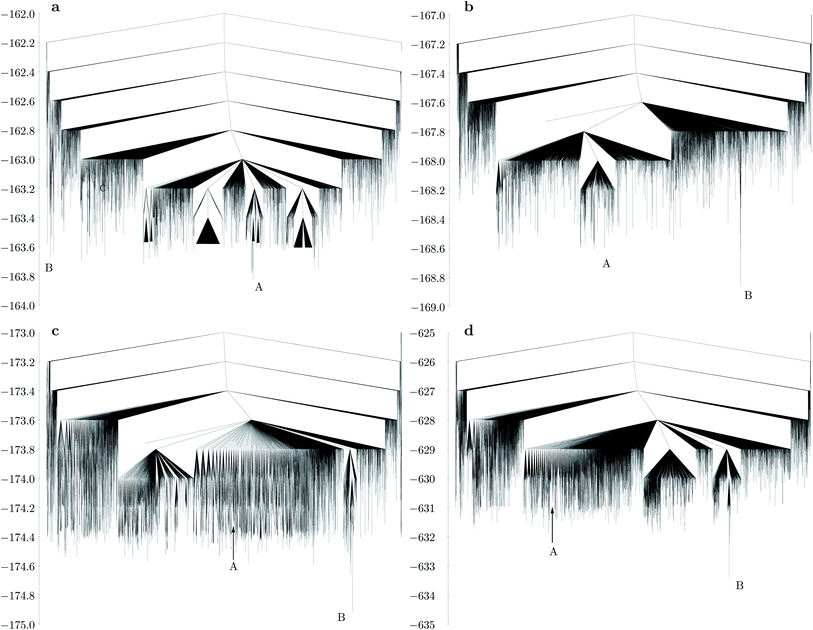 | ||
| Fig. 5 Disconnectivity graphs for M30L60 with different bend angles in the L particle: (a) dy = 0.2, 164.81°; (b) dy = 0.4, 150.14°; (c) dy = 0.6, 136.39°; (d) same bend angle as in (c), but with a three times stronger Coulomb interaction (εQ = 3). A represents the chiral tetravalent Goldberg structure, B is the structure with icosahedral symmetry. Both structures are depicted in Fig. 2b. | ||
4. Conclusions
In conclusion, we have created a simple model that assembles into highly symmetric low-energy shells composed of two types of rigid building blocks, using only isotropic excluded volume and coulombic pairwise interactions between the sites. To the best of our knowledge, no other coarse-grained model supports global minima corresponding to tetravalent Goldberg shells. We have also identified highly cooperative interconversion mechanisms between competing structures that correspond to overall rotatory motions. Such pathways can be further exploited in the computational design of mesoscale motors. The interactions are simple enough to be experimentally realisable on the colloidal length scale.Author contributions
SNF and DJW designed the simulations, IH and SNF conducted the simulations, all authors analysed the results and wrote the paper.Conflicts of interest
There are no conflicts to declare.Acknowledgements
This work was supported by a grant of the Romanian Ministry of Research and Innovation, CNCS-UEFISCDI, project number PN-III-P1-1.1-TE-2019-1018, within PNCDI III.References
- Q.-F. Sun, J. Iwasa, D. Ogawa, Y. Ishido, S. Sato, T. Ozeki, Y. Sei, K. Yamaguchi and M. Fujita, Science, 2010, 328, 1144–1147 CrossRef CAS PubMed.
- D. Fujita, H. Yokoyama, Y. Ueda, S. Sato and M. Fujita, Angew. Chem., Int. Ed., 2015, 54, 155–158 CrossRef CAS PubMed.
- Y. Tachi, S. Sato, M. Yoneya, M. Fujita and Y. Okamoto, Chem. Phys. Lett., 2019, 714, 185–189 CrossRef CAS.
- M. Yoneya, T. Yamaguchi, S. Sato and M. Fujita, J. Am. Chem. Soc., 2012, 134, 14401–14407 CrossRef CAS PubMed.
- M. Yoneya, S. Tsuzuki, T. Yamaguchi, S. Sato and M. Fujita, ACS Nano, 2014, 8, 1290–1296 CrossRef CAS PubMed.
- D. Fujita, Y. Ueda, S. Sato, N. Mizuno, T. Kumasaka and M. Fujita, Nature, 2016, 540, 563–566 CrossRef CAS PubMed.
- M. Goldberg, Tohoku Math. J., 1937, 43, 104–108 Search PubMed.
- F. Li, D. P. Josephson and A. Stein, Angew. Chem., Int. Ed., 2011, 50, 360–388 CrossRef CAS PubMed.
- E. Duguet, A. Désert, A. Perro and S. Ravaine, Chem. Soc. Rev., 2011, 40, 941–960 RSC.
- Y. Wang, Y. Wang, D. R. Breed, V. N. Manoharan, L. Feng, A. D. Hollingsworth, M. Weck and D. J. Pine, Nature, 2012, 491, 51–55 CrossRef CAS PubMed.
- A. Perro, E. Duguet, O. Lambert, J.-C. Taveau, E. Bourgeat-Lami and S. Ravaine, Angew. Chem., Int. Ed., 2009, 48, 361–365 CrossRef CAS PubMed.
- S. N. Fejer, D. Chakrabarti and D. J. Wales, ACS Nano, 2010, 4, 219–228 CrossRef CAS PubMed.
- S. N. Fejer and D. J. Wales, Phys. Rev. Lett., 2007, 99, 086106 CrossRef PubMed.
- S. N. Fejer, D. Chakrabarti and D. J. Wales, Soft Matter, 2011, 7, 3553–3564 RSC.
- S. N. Fejer and D. J. Wales, Soft Matter, 2015, 11, 6663–6668 RSC.
- D. J. Wales and J. P. K. Doye, J. Phys. Chem. A, 1997, 101, 5111 CrossRef CAS.
- D. Chakrabarti and D. J. Wales, Phys. Chem. Chem. Phys., 2009, 11, 1970–1976 RSC.
- S. W. Olesen, S. N. Fejer, D. Chakrabarti and D. J. Wales, RSC Adv., 2013, 3, 12905–12908 RSC.
- D. J. Wales, Chem. Phys. Lett., 1998, 285, 330–336 CrossRef CAS.
- D. Wales, Energy Landscapes: Applications to Clusters, Biomolecules and Glasses, Cambridge University Press, 2003 Search PubMed.
- F. Stillinger and T. Weber, J. Stat. Phys., 1988, 52, 1429–1445 CrossRef.
- D. J. Wales, Mol. Phys., 2002, 100, 3285–3305 CrossRef CAS.
- O. M. Becker and M. Karplus, J. Chem. Phys., 1997, 106, 1495–1517 CrossRef CAS.
- D. J. Wales, M. A. Miller and T. R. Walsh, Nature, 1998, 394, 758–760 CrossRef CAS.
- I. Santiago, Nano Today, 2018, 19, 11–15 CrossRef CAS.
- M. S. Gravett, R. C. Cocking, A. P. Curd, O. Harlen, J. Leng, S. P. Muench, M. Peckham, D. J. Read, J. F. Rogers and R. C. Welch, et al. , Wiley Interdiscip. Rev.: Comput. Mol. Sci., 2022, 12, e1570 CAS.
- J. A. Anderson, C. D. Lorenz and A. Travesset, J. Comput. Phys., 2008, 227, 5342–5359 CrossRef.
- J. Glaser, T. D. Nguyen, J. A. Anderson, P. Lui, F. Spiga, J. A. Millan, D. C. Morse and S. C. Glotzer, Comput. Phys. Commun., 2015, 192, 97–107 CrossRef CAS.
- D. N. LeBard, B. G. Levine, P. Mertmann, S. A. Barr, A. Jusufi, S. Sanders, M. L. Klein and A. Z. Panagiotopoulos, Soft Matter, 2012, 8, 2385–2397 RSC.
Footnote |
| † Electronic supplementary information (ESI) available: Alternative parameterisation of the potential that gives rise to hollow shells of the same symmetry than those presented in the paper, MD simulation snapshots and trajectory analyses. Supplementary Movie 1: Change of the potential energy surface shown in Fig. 1 as the ‘ligand’ particle is rotated in-plane around a vertical axis centered on site D. Supplementary Movie 2: Highly cooperative low-energy single transition state rearrangement between a pseudorhombicuboctahedral structure and the rhombicuboctahedral global minimum (right panel of Fig. 3). Supplementary Movie 3: Lowest energy pathway for interconversion between the tetravalent Goldberg global minimum and the icosahedral structure shown in Fig. 2b. Supplementary Movie 4: Smoothed molecular dynamics trajectory for M30L60, showing the final steps of assembly into an icosahedral structure. trajectories.zip: an archived folder containing the input files and MD trajectories. See https://doi.org/10.1039/d2na00447j |
| This journal is © The Royal Society of Chemistry 2022 |

