 Open Access Article
Theoretical investigations on the superhydrophobicity of intrinsic hydrophilic surfaces with overhang microstructures
P. Xua,
J. R. Baia,
P. Zhoua,
L. L. Wanga,
X. N. Suna,
L. Wei *bc and
Q. F. Zhou*a
aResearch Center of Resources and Environment and School of Chemical Engineering and Materials, Changzhou Institute of Technology, Changzhou 213022, P. R. China. E-mail: zhouqf123@126.com
bSchool of Chemical Engineering, Henan University of Science and Technology, Zhengzhou 450000, P. R. China. E-mail: fdxsbd@163.com
cDepartment of Chemical Engineering, Kansas State University, Manhattan, KS 66506, USA
First published on 20th January 2022
Abstract
It has been accepted generally that it is necessary to obtain the so-called surface superhydrophobicity on intrinsically hydrophobic materials. However, recent experiments have indicated that it could be possible to prepare superhydrophobic surfaces on intrinsically hydrophilic materials by creating adequate roughness. In this work, such a strategy for surface superhydrophobicity on hydrophilic materials with an intrinsic contact angle less than 90° was demonstrated thermodynamically based on a proposed 2-D analytical model. In particular, different (trapezoidal, vertical and inverse-trapezoidal) microstructures were employed to analyze their wetting states such as composite and noncomposite and superhydrophobic behavior as well as the previous corresponding experimental observations. Based on the thermodynamic calculations, it was demonstrated that for an overhang microstructure, intrinsic contact angle, which was restricted by the sidewall angle of micropillars, was not an independent parameter to affect superhydrophobicity. Furthermore, an overhang microstructure was critical to realize the transition from hydrophilicity to superhydrophobicity, and for such a transition, the sidewall angle should be less than the intrinsic contact angle where a positive free energy barrier could support the liquid/vapor interfaces and separate the Wenzel and Cassie states on such hydrophilic surfaces. Most importantly, it was found that for such hydrophilic surfaces, generally, the free energy of the noncomposite or Wenzel states were lower than that of the composite or Cassie states for those trapezoidal, vertical and inverse-trapezoidal microstructures, implying that once a noncomposite state was formed, it can hardly become a composite state, or in other words, even if superhydrophobic behavior was possible, it could be temporary or unstable.
1. Introduction
It is well known that the wettability of solid surfaces is not only dependent upon their chemical compositions but also closely related to the micro/nano-structures on their surfaces.1–3 Superhydrophobic surfaces with large water contact angles (CAs) and small contact angle hysteresis (CAH) have attracted strong interest in various industries due to their unique liquid-shedding or droplet-sliding properties over the past two decades.4–8 The excellent wettability of these surfaces has shown wide potential applications, such as self-cleaning glasses, biological scaffolds, microfluidics, lab-on-a-chip devices, coatings for automotive and aerospace vehicles, and textiles.9–11Although hydrophobicity can be enhanced by a chemical modification that lowers the surface energy, contact angles larger than 120° have never been achieved for water on ideal flat surfaces. Therefore it is generally thought that all superhydrophobic surfaces result from originally hydrophobic substrates with surface microstructures. This has been demonstrated well, e.g., for a CA of the order of 100–120° on such flat surfaces, a microstructured or rough surface shows an amplified CA as high as 150–175°.12–15
However, some studies indicted that roughness can also lead to the superhydrophobicity on a hydrophilic surface. For example, for example, Otten et al. have found that a water droplet can be held by hydrophilic hairs on the leaves of Lady's Mantle.16 Apart from leaves of natural plant, some artificial superhydrophobic surfaces have been prepared on some hydrophilic materials without low surface energy modification.17–20 Furthermore, two approaches to achieve hydrophobicity on inherently hydrophilic surfaces have been developed. One is to make hydrophilic substrates with cavities and the trapped air in cavities can inhibit the liquid from wetting the surface. Abdelsalam et al. have proved that the contact angle of gold surfaces can be larger than 130° if the substrates are decorated with 400–800 nm pores.18 The other one is to prepare re-entrant or overhang microstructures, such as T-shape or inverse-trapezoidal structures, on substrates.19–22 Cao et al. showed that the overhang microstructures can induce superhydrophobicity on Si substrates with an intrinsic contact angle 74°.19 Furthermore, it has proved that the T-shape microstructures can induce superhydrophobic behaviors on hydrophilic surfaces without any organic modifications.22
Although the above results have experimentally demonstrated that the superhydrophobicity can be achieved on hydrophilic surfaces with very rough microstructures. However, the theoretical explanations have not been completely understood. For example, Liu et al.23 studied closed/airproofed microstructures and some special topologies of the pillars or hairs on solid hydrophilic substrates, considering the effect of Laplace pressure and a certain geometric condition on the formation of Cassie's state. Marmur24 theoretically analyzed the possibility of high contact angle from low contact angle surfaces for concave and convex roughness topographies and found that concave parts of roughness topographies may not enable a Cassie's state, while convex roughness features may enable the formation of hydrophobic surfaces from hydrophilic materials. On the contrary, Patankar25 considered the energy of drops on surfaces with cavities, and theoretically explained the possibility of hydrophobic surfaces with cavities from hydrophilic materials. In addition, McHale26 compared the surface free energy (FE) changes based on Young's law, and explained hydrophobic tendencies induced the roughness hydrophilic solid surfaces. Here it is noted that the above studies are in agreement with specific experimental observations, and can advance our understanding of superhydrophobic behavior on hydrophilic surfaces. However, these studies have never addressed the stability for such superhydrophobic behavior. In particular, the explanations and discussions about local surface curvatures in these studies are qualitative. Therefore, it is necessary to conduct a quantitative thermodynamic analysis on the superhydrophobicity on hydrophilic surfaces, especially, with a overhang microstructure.
In this work, based on a proposed 2-D model, we mainly investigate and analyze thermodynamic states and wetting behavior of the above overhang microstructures with an aim at the possibility of superhydrophobicity on hydrophilic surfaces. By such an analysis of free energy states, the effects of topographical features and in particular, intrinsic hydrophilic surfaces on contact angle and contact angle hysteresis as well as composite or Cassie's state can be obtained in order to reveal the thermodynamic mechanism for the superhydrophobicity on hydrophilic surfaces.
2. Thermodynamic analysis
2.1. General 2-D model
The contact angle (CA) of a droplet on an ideal smooth solid surface can be given by classical Young's equation
γla![[thin space (1/6-em)]](https://www.rsc.org/images/entities/char_2009.gif) cos cos![[thin space (1/6-em)]](https://www.rsc.org/images/entities/char_2009.gif) θY = γsa − γls θY = γsa − γls
| (1) |
cos![[thin space (1/6-em)]](https://www.rsc.org/images/entities/char_2009.gif) θW = r θW = r![[thin space (1/6-em)]](https://www.rsc.org/images/entities/char_2009.gif) cos cos![[thin space (1/6-em)]](https://www.rsc.org/images/entities/char_2009.gif) θY θY
| (2) |
| r = 1 + 2h/(a + b) | (3) |
However, the apparent contact angle for the composite can be calculated using Cassie's equation28
cos![[thin space (1/6-em)]](https://www.rsc.org/images/entities/char_2009.gif) θC = fs θC = fs![[thin space (1/6-em)]](https://www.rsc.org/images/entities/char_2009.gif) cos cos![[thin space (1/6-em)]](https://www.rsc.org/images/entities/char_2009.gif) θY + fs − 1 θY + fs − 1
| (4) |
| fs = a/(a + b) = 1/(1 + b/a) | (5) |
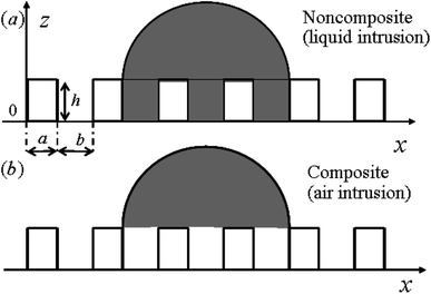
Based on the previous studies,29,30 a 2-D model is proposed to analyze the pillar microstructured surface with a set of geometrical parameters (see Fig. 1). Therefore the thermodynamic analysis of the wetting states related to the surface texture geometry and numerical calculations of free energy and free energy barrier corresponding to contact angle and contact angle hysteresis respectively can be conducted by the free energy and geometrical equations. For this model, some assumptions for the thermodynamic analysis should be followed as:29,30
(1) It is generally accepted that the gravity, chemical heterogeneity and interactions between water and solid and between fluidic molecules within droplet and molecules within solid can be ignored.
(2) The droplet is millimeter scale and is large enough comparing with the dimension of surface asperities. As a result, the line tension, i.e., the excess free energy of a solid–liquid–air system per unit length of the three-phase contact line, becomes extremely small and makes little contribution to the wettability for such a macroscopic droplet.
(3) Based on the above assumptions, the droplet is spherical in the absence of gravity and liquid volume conservation can be kept. Therefore on a horizontal solid surface, this assumption is reasonable as the gravity centre of the droplet will not change significantly as a result of the liquid front movement. Thus, in the present 2-D model, the droplet area should be constant.
For the noncomposite state (see Fig. 1), if a infinite small change, the droplet advances from reference point A (associated with CA of θA and droplet size LA) to the neighboring point B (associated with CA of θB and droplet size LB) (see Fig. 2). Due to the constant droplet area in x–z plane for the 2-D model, i.e., the constant droplet volume for a 3-D model, the geometrical equation can be expressed as:
 | (6) |
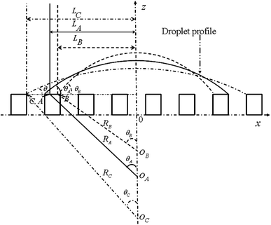 | ||
| Fig. 2 Schematic of variation of wetting states for a droplet from state A to B (or to C) along the contact line. | ||
The free energy for the two states can be written as, respectively.
 | (7) |
 | (8) |
 | (9) |
If the droplet recedes from A to the neighboring point C (associated with CA of θC and droplet size LC, respectively) (see Fig. 2), the equivalent equations can be expressed as:
 | (10) |
 | (11) |
Therefore, similarly, for the composite state, the droplet advances from reference point A to the neighboring point B or recedes from A to the neighboring point C (see Fig. 2), the geometrical equation can be expressed as:
 | (12) |
 | (13) |
 | (14) |
 | (15) |
It should be pointed out that a reference free energy state is assigned as a value of zero by a random choice (e.g., the instantaneous position A) with the initial drop size L0 and θ0, respectively. Hence, the reference state will not impact the results of free energy barrier, which is a relative value with respect to its neighbors (e.g., B and C). Hence, the free energy barrier such as ΔF![[A with combining right harpoon above (vector)]](https://www.rsc.org/images/entities/char_0041_20d1.gif) B and ΔF
B and ΔF![[A with combining right harpoon above (vector)]](https://www.rsc.org/images/entities/char_0041_20d1.gif) C can be determined by successive applications and numerical computations. Similarly, geometrical constraint and free energy barrier equations for other arbitrary instantaneous position can be derived.
C can be determined by successive applications and numerical computations. Similarly, geometrical constraint and free energy barrier equations for other arbitrary instantaneous position can be derived.
2.2. Unified treatments
In the present work, based on the above general 2-D model, for the different overhang microstructures, further unified treatments are conduct necessary in order to investigate effects of all the topographical features and geometrical parameters on superhydrophobic behavior on intrinsic hydrophilic surfaces. In particular, unit height free energy barriers (UHFEB) is proposed to clarify the thermodynamic mechanism for the superhydrophobicity on hydrophilic rough surfaces.For a comparison, three different surface microstructures with inverse-trapezoidal pillars, vertical pillars and trapezoidal pillars were employed in the present work, as shown in Fig. 3. For the unified treatments, α was defined as sidewall angle, H was pillar height, a was pillar width, and b was pillar spacing. If the liquid/vapor interfaces moved down the pillars, the intermediate state would form, and the penetration depth of the drop was defined h (Fig. 3(c)). Because the drop was spherical, the drop length Lk equaled R![[thin space (1/6-em)]](https://www.rsc.org/images/entities/char_2009.gif) sin
sin![[thin space (1/6-em)]](https://www.rsc.org/images/entities/char_2009.gif) θhk where R was radius, and θhk was the apparent contact angle if the penetration depth was h (Fig. 3(b) and (c)). The number of micro-pillars contacted with the drop can therefore be expressed as:
θhk where R was radius, and θhk was the apparent contact angle if the penetration depth was h (Fig. 3(b) and (c)). The number of micro-pillars contacted with the drop can therefore be expressed as:
| n = (2Lk + b)/(a + b) | (16) |
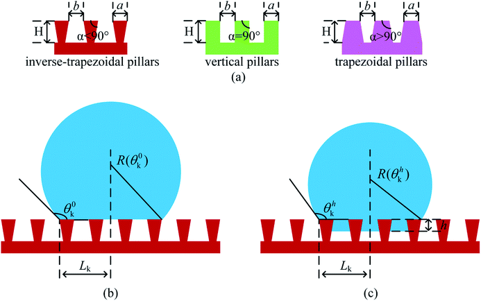 | ||
| Fig. 3 Schematic of overhang microstructures with a droplet. (a) Three different profiles of surface geometry; (b) Cassie state; (c) intermediate state. | ||
For the vertical pillar microstructure, the geometrical equation can be expressed as:
 | (17) |
If the penetration depth of the drop was h (Fig. 3(c)), the free energy can be expressed as:
| Eh = γSVLhSV + γSLLhSL + γLVLhLV | (18) |
 | (19) |
The UHFEB Eu can therefore be defined as the limit of ΔE/Δh as Δh → 0, as shown:
 | (20) |
This indicates that UHFEB can be regarded as the free energy change if liquid/vapor interfaces moved down per unit height. From the above equations and Young's equation, UHFEB can further be normalized with respect to γLV, as shown:
γSV = γSL + γLV![[thin space (1/6-em)]](https://www.rsc.org/images/entities/char_2009.gif) cos cos![[thin space (1/6-em)]](https://www.rsc.org/images/entities/char_2009.gif) θY θY
| (21) |
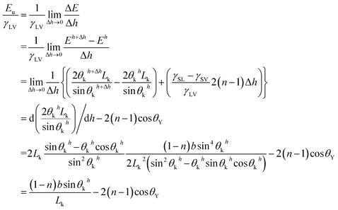 | (22) |
Similarly, for the trapezoidal and inverse-trapezoidal microstructures, the geometrical and normalized UHFEB equations can be expressed as:
 | (23) |
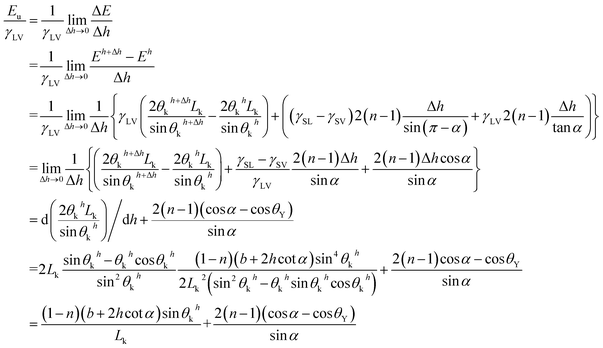 | (24) |
3. Results and discussion
3.1. Changes in free energy and free energy barrier with contact angle
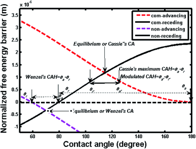
Fig. 4 shows two free energy curves of composite and noncomposite states for a pillar microstructure (a = b = 2 μm, h = 2 μm). One can see that there is only one global free energy minimum for each curve, which is associated with the equilibrium contact angle (ECA/θE) and exactly corresponds to generalized Cassie's contact angle (e.g., θC = 114.4°) and Wenzel's contact angle (e.g., θW = 69.68°), respectively. However, it should be noted that if drop advances from a position A to B or recedes from A to C, the contact angle changes and the local curve can show a fluctuation in free energy, as illustrated in the inset of Fig. 4. These fluctuations demonstrate that the free energy curve contains multi-valued local minimum free energy and maximum free energy, indicating that such extremes represent metastable and unstable equilibrium states, which are related to various apparent contact angles. Therefore, the free energy barrier refers to the difference between local minimum and maximum in the direction of three-phase line motion, i.e., advancing and receding. Furthermore, there are always two free energy barriers, i.e., advancing free energy barrier and receding free energy barrier, connected to each contact angle value.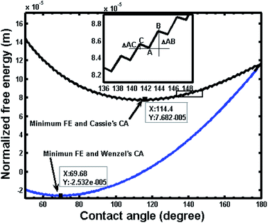 | ||
| Fig. 4 Variation of normalized free energy with contact angle for noncomposite (non) and composite (com) states (L = 10−2 m, a = b = h = 2 μm; intrinsic contact angle, θY = 80°; θW = 69.68°, θC = 114.4°). The inset shows an enlarge view of a segment of free energy curve illustrating the free energy barrier; positions A, B and C correspond to those in Fig. 2. ΔAB and ΔAC represent the free energy barrier for retreating and advancing contact line, respectively. | ||
Fig. 5 shows the advancing and receding free energy barrier for both composite and noncomposite states based on the same geometrical parameters as shown in Fig. 1. Hence, the advancing contact angle (θa) and receding contact angle (θr) as well as contact angle hysteresis defined as (θa − θr) can be determined by the intersecting values of advancing and receding curves with x-axis, respectively. As a result, for the composite state, the advancing (θa = 180°) and receding (θr = θY = 80°) contact angles as well as the maximum theoretical contact angle hysteresis defined as (contact angle hysteresis = θa − θr = 100°) can be determined.
3.2. Effect of sidewall angle
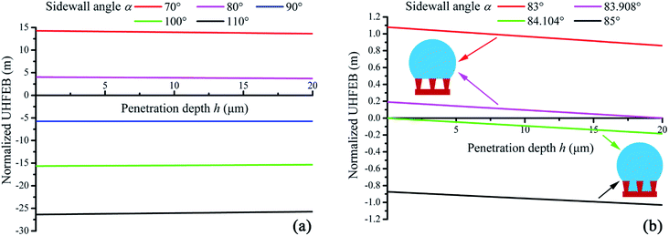
Through eqn (22) and (24), the normalized UHFEB of different surface structures could be calculated numerically. Here it should be indicted that because the free energy (J m−1) had been normalized with respect to γLV (J m−2) in eqn (22) and (24), the unit of normalized UHFEB should be meter. Fig. 6(a) shows a typical change of UHFEB curves on hydrophilic surfaces with inverse-trapezoidal pillars, vertical pillars, and trapezoidal pillars where their sidewall angle α varies, respectively. It could be seen that the value of normalized UHFEB did not change greatly with different penetration depth, and the normalized UHFEB curve would shift down with the increasing sidewall angle α. If the sidewall angle was 70° and 80°, the normalized UHFEB would be larger than 13.6 m and 3.7 m respectively even if the intrinsic contact angle was 85° (Fig. 6(a)). Here it is noted that as indicated above, although the unit of the normalized UHFEB was meter in the present work, in fact, it represented the free energy change. If the liquid/vapor interfaces moved down per unit height, its value could reach meter order. When the normalized UHFEB was always positive, and the system would prefer Cassie state. It meant that a composite interface could appear on the inverse-trapezoidal microstructure surface. Therefore, it proved the experimental observation that superhydrophobicity could be induced on hydrophilic surfaces.19For the inverse-trapezoidal pillar microstructure, Fig. 6(b) shows the critical curve (green curve) about wetting transition. If the sidewall angle increased from 83° to 85°, the normalized UHFEB would become negative and wetting transition would start. If the angle was larger than the critical value 84.104°, the negative UHFEB curve indicated a fully wetted interface would occur since the Wenzel state was more stable than the Cassie state. From the viewpoint of thermodynamics, the above results showed that the stability of a composite interface could be amplified with a decreasing sidewall angle, since a higher UHFEB could inhibit wetting transition. Hence, these results also theoretically explained the experimental phenomena why inverse-trapezoidal micro-textures superhydrophobic surface could perform excellent robustness (not the mechanical robustness).31
From Fig. 6(b), it was also seen that whether the Cassie state could appear mainly depended on the value of normalized UHFEB when penetration depth h was zero (E0u).
Fig. 7 shows the effects of sidewall angle on the wetting states on hydrophilic and hydrophobic surfaces. One can see that the increasing intrinsic contact angle could bring a higher E0u, regardless of the dimensions of the microstructures, implying that a large intrinsic contact angle was preferred for a stable superhydrophobicity. The critical value of intrinsic contact angle (the curve intersecting with the E0u = 0 line) was 70.86° if the sidewall angle was 70°. The positive E0u indicated that a composite interface could appear if θY was in the range of 70.86° to 120°. If the sidewall angle increased from 70° to 110°, the critical value could also increase from 70.86° to 110.97°, implying that a small sidewall angle was crucial for the Cassie state even if the surface was hydrophobic (the critical value of θY larger than 90° for green and pink curves in Fig. 7 due to a large α). Generally, Wenzel's equation indicated that a rough surface would become more hydrophilic if substrates were hydrophilic. However, the results in Fig. 7 show that the intrinsic contact angle, which was restricted by the sidewall angle of rough micro-textures, was not an independent parameter to determine the superhydrophobicity. Therefore, it was important to note that besides pillar width and spacing, the sidewall angle also played a very important role in the superhydrophobic behavior, especially for the transition from noncomposite to composite wetting states on hydrophilic surfaces.
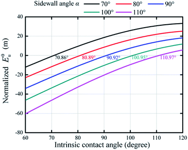 | ||
| Fig. 7 Variations of normalized E0u with respect to intrinsic contact angles for different sidewall angles (a = 20 μm, b = 20 μm, H = 20 μm, S = 10−6 m2). | ||
3.3. Effect of pillar width and pillar spacing
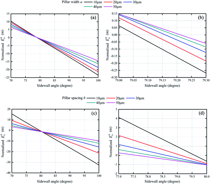
Variations in normalized E0u with respect to sidewall angle α was shown in Fig. 8 for different pillar dimensions. Apparently, effects of pillar width and pillar spacing on normalized E0u were quite similar. From Fig. 8(a), as pillar width increased from 10 μm to 50 μm, the maximum value of normalized E0u decreased from 10.4 m to 6.5 m if the sidewall angle was 70°. And the maximum value of normalized E0u also decreased from 15.6 m to 3.4 m with increasing pillar spacing in Fig. 8(c). These results indicated that the smaller pillar dimensions, the more stable composite states could be. However, in terms of inducing the transition from hydrophilicity to superhydrophobicity, such effects of pillar width and spacing could hardly become apparent. From the previous thermodynamic analysis, a small sidewall angle was crucial to obtain free energy barriers to separate the Wenzel state and Cassie state irrespective of solid surface chemistry. However, the critical value of sidewall angle (the curve intersecting with the E0u = 0 line) changed slightly with different pillar width and spacing in Fig. 8(b) and (d). With pillar width changing, the critical value of sidewall angle ranged from 79.06° to 79.21°, while they were in the 77.62–79.60° range for different pillar spacing. The change of the critical value were only 0.15° and 1.98°, respectively for pillar width and pillar spacing varying in the range of 10 μm to 50 μm. It could be argued that since for preparing microstructures, the control of sidewall angle with such an accuracy is impossible experimentally, the pillar width and spacing could hardly play a crucial role in achieving the superhydrophobicity on a hydrophilic surface, but both affected its stability for this superhydrophobic surface.3.4. Transition of the Cassie state on hydrophilic surfaces
For the wetting transition conditions, the normalized UHFEB should be positive from eqn (22) and (24). Based on eqn (24), the sidewall angle α of pillars should be less than intrinsic contact angle if a positive E0u was expected. Apparently, if α was less than intrinsic contact angle θY, the change of the free energy ΔE could be positive, implying that positive free energy barriers could appear even if a droplet was placed on hydrophilic surfaces with overhang microstructures. Although it was energetically favorable for the droplet to wet the hydrophilic surfaces, the Cassie state could be metastable because extra free energy was needed to overcome the energy barriers during the wetting process.32 The criterion of inducing the transition from hydrophilicity to superhydrophobicity was therefore derived as α < θY. In terms of the previous experimental results, Cao et al.19 prepared an overhanging microstructure with a sidewall angle of 35.3° and 54.7° to achieve the superhydrophobicity on Si substrates with intrinsic contact angle 74°, which were also compatible with the present theoretical analysis.3.5. Comparisons of free energy and free energy barriers between noncomposite and composite states
The above results indicated that for a hydrophilic surface, superhydrophobic behavior can be achieved. Nevertheless, our further theoretical investigations on the direct comparisons of free energy and free energy barriers between noncomposite and composite states indicated that such a superhydrophobicity could be unstable or temporary. Fig. 9 shows the free energy change of a wetting system on the hydrophilic surface (θY = 85°) for a inverse-trapezoidal microstructure. As seen, for both composite and noncomposite wetting states, their free energy first decreased and then increased, i.e., there was a valley with a minimum value, respectively, where the so-called equilibrium contact angle located. It is very interesting to note that the curve for the composite states was above the one for the noncomposite states, i.e., the free energy for the composite states was always higher than the one for the noncomposite states, implying that the composite states were metastable. This indicated that for such a hydrophilic surface, from the viewpoint of thermodynamics, a droplet on this surface would tend to wet the rough microstructure. Further calculations confirmed that there was a large positive free energy barriers between the composite and noncomposite states. The above results therefore provided a solid support for the difficult and complexity to realize the superhydrophobicity on hydrophilic surfaces or materials although now it has been recognized that any efforts in both theoretical and practical aspects could be feasible.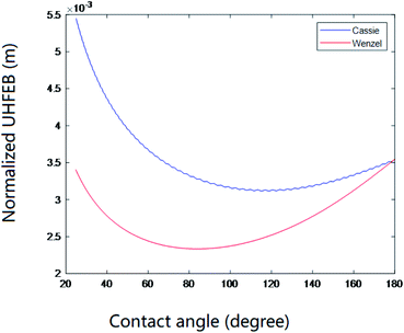 | ||
| Fig. 9 Free energy variations with contact angle (a = 20 μm, b = 20 μm, H = 20 μm, θY = 85°, and S = 10−6 m2). | ||
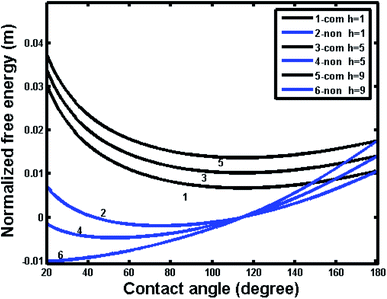
To further understand the superhydrophobic behavior on intrinsic hydrophilic materials, the calculations were also extend to investigate the effects of various geometrical parameters for different intrinsic contact angles. For the simplicity, we employ the pillar microstructure as a typical example. Fig. 10 shows the free energy variations for the noncomposite and composite wetting systems with the intrinsic contact angle of 80° for different pillar heights. One can see that the curves of both noncomposite and composite states intersect at 180° for the same geometry, indicating the same energy state for the noncomposite and composite states. The free energy of composite states for the present system is always higher than that of noncomposite states for different pillar heights, implying that the composite states for this system were more unstable than the noncomposite states.
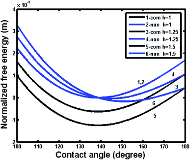
In contrast, Fig. 11 shows the free energy variations with respect contact angle for noncomposite and composite wetting systems with an intrinsic contact angle of 120° for different pillar heights. One can see that the composite state was more stable that the noncomposite state for different pillar heights. In particular, compared Fig. 10 to Fig. 11, it was important to note that the free energy of hydrophilic materials was higher than that of hydrophobic materials; the former had a magnitude of 10−2 m, whereas the later had a magnitude of 10−3 m. The above results indicated that the thermodynamic state for hydrophilic materials was more unstable than that for the hydrophobic materials. Therefore, even though a composite state for hydrophilic materials can be formed, the corresponding superhydrophobicity may be temporary and tend to transfer to hydrophilicity with time, especially, in case of external stimulus such as vibrational energy.30
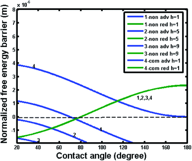
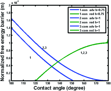
In order to further reveal the intrinsic effect of different materials (hydrophilic or hydrophobic), Fig. 12 and 13 show the free energy barrier variations for the noncomposite and composite wetting systems with the intrinsic contact angle of 80° and 120°, respectively. From Fig. 12, one can see that the free energy barrier and the resultant contact angle hysteresis of the composite state could hardly depend on pillar height. It was important note that the negative free energy barrier indicated that there was not enough energy to provide a transition between noncomposite and composite states. Comparatively, from Fig. 13, one also can see that for an intrinsic contact angle of 120°, the free energy barrier and the resultant contact angle hysteresis of the composite state could not depend on pillar height. However, for the noncomposite state, the contact angle hysteresis increased and there was a positive free energy barrier, implying that there was enough energy to provide a transition between noncomposite and composite states. Here it is worth noting that some experimental studies suggested that such a transition was plausible.33,34 For example, for hydrophilic materials with an intrinsic contact angle of 70°, a transition from noncomposite to composite states could occur if the depth of surface topography pores (a similar parameter to the pillar height) was very large. This happens perhaps because the difference in free energy and barrier between the noncomposite to composite states was so small due to adequate roughness that the transition between the two states could be easily realized under the experimental conditions where external resources may be available.
4. Conclusions
The possibility for the surface superhydrophobicity on hydrophilic materials with an intrinsic contact angle less than 90° was investigated thermodynamically based on a 2-D model. In particular, different (trapezoidal, vertical and inverse-trapezoidal) microstructures were employed to analyze their wetting states such as composite and noncomposite and superhydrophobic behavior as well as the previous corresponding experimental observations. The results show that for a overhang microstructure, intrinsic contact angle was not an independent parameter to affect superhydrophobicity. Furthermore, a overhang microstructure was critical to realize the transition from hydrophilicity to superhydrophobicity, and for such a transition, the sidewall angle should be less than the intrinsic contact angle where a positive free energy barrier could support the liquid/vapor interfaces and separate the Wenzel and Cassie states on such hydrophilic surfaces. Most importantly, it was found that for such hydrophilic surfaces, generally, the free energy of the noncomposite or Wenzel's states were lower than that of the composite or Cassie's states for those trapezoidal, vertical and inverse-trapezoidal microstructures, implying that once a noncomposite state was formed, it can hardly be become a composite state, or in other words, even if superhydrophobic behavior was possible, it could be temporary or unstable.Conflicts of interest
There are no conflicts to declare.Acknowledgements
This work was supported by ChangZhou Institute of Technology (YN18039).References
- M. Ma and R. M. Hill, Superhydrophobic surfaces, Curr. Opin. Colloid Interface Sci., 2006, 11, 193–202, DOI:10.1016/j.cocis.2006.06.002.
- F. Xia and L. Jiang, Bio-Inspired, Smart, Multiscale Interfacial Materials, Adv. Mater., 2008, 20, 2842–2858, DOI:10.1002/adma.200800836.
- Y. L. Zhang, H. Xia, E. Kim and H. B. Sun, Recent developments in superhydrophobic surfaces with unique structural and functional properties, Soft Matter, 2012, 8, 11217–11231, 10.1039/c2sm26517f.
- S. S. Latthe, R. S. Sutar, V. S. Kodag, A. K. Bhosale, A. M. Kumar, K. Kumar Sadasivuni, R. Xing and S. Liu, Self – cleaning superhydrophobic coatings: Potential industrial applications, Prog. Org. Coat., 2019, 128, 52–58, DOI:10.1016/j.porgcoat.2018.12.008.
- J. Peng, X. Zhao, W. Wang and X. Gong, Durable Self-Cleaning Surfaces with Superhydrophobic and Highly Oleophobic Properties, Langmuir, 2019, 35, 8404–8412, DOI:10.1021/acs.langmuir.9b01507.
- B. Bhushan, Y. C. Jung and K. Koch, Self-cleaning efficiency of artificial superhydrophobic surfaces, Langmuir, 2009, 25, 3240–3248, DOI:10.1021/la803860d.
- S. Yanlong, Y. Wu, F. Xiaojuan, W. Yongsheng, Y. Guoren and J. Shuping, Fabrication of superhydrophobic–superoleophilic copper mesh via thermal oxidation and its application in oil–water separation, Appl. Surf. Sci., 2016, 367, 493–499, DOI:10.1016/j.apsusc.2016.01.233.
- W. T. Cao, Y. J. Liu, M. G. Ma and J. F. Zhu, Facile preparation of robust and superhydrophobic materials for self-cleaning and oil/water separation, Colloids Surf., A, 2017, 529, 18–25, DOI:10.1016/j.colsurfa.2017.05.064.
- U. Baig, A. Matin, M. A. Gondal and S. M. Zubair, Facile fabrication of superhydrophobic, superoleophilic photocatalytic membrane for efficient oil–water separation and removal of hazardous organic pollutants, J. Cleaner Prod., 2019, 208, 904–915, DOI:10.1016/j.jclepro.2018.10.079.
- Y. C. Liu, W. J. Huang, S. H. Wu, M. Lee, J. M. Yeh and H. H. Chen, Excellent superhydrophobic surface and anti-corrosion performance by nanostructure of discotic columnar liquid crystals, Corros. Sci., 2018, 138, 1–7, DOI:10.1016/j.corsci.2018.03.044.
- P. Chauhan, A. Kumar and B. Bhushan, Self-cleaning, stain-resistant and anti-bacterial superhydrophobic cotton fabric prepared by simple immersion technique, J. Colloid Interface Sci., 2019, 535, 66–74, DOI:10.1016/j.jcis.2018.09.087.
- H. Bai, L. Wang, J. Ju, R. Sun, Y. Zheng and L. Jiang, Efficient water collection on integrative bioinspired surfaces with star-shaped wettability patterns, Adv. Mater., 2014, 26, 5025–5030, DOI:10.1002/adma.201400262.
- J. W. Gose, K. Golovin, M. Boban, J. M. Mabry, A. Tuteja, M. Perlin and S. L. Ceccio, Characterization of superhydrophobic surfaces for drag reduction in turbulent flow, J. Fluid Mech., 2018, 845, 560–580, DOI:10.1017/jfm.2018.210.
- Y. Tuo, W. Chen, H. Zhang, P. Li and X. Liu, One-step hydrothermal method to fabricate drag reduction superhydrophobic surface on aluminum foil, Appl. Surf. Sci., 2018, 446, 230–235, DOI:10.1016/j.apsusc.2018.01.046.
- A. Rajappan, K. Golovin, B. Tobelmann, V. Pillutla, B. Abhijeet, A. Tuteja and G. H. McKinley, Influence of textural statistics on drag reduction by scalable, randomly rough superhydrophobic surfaces in turbulent flow, Phys. Fluids, 2019, 31, 042107, DOI:10.1063/1.5090514.
- A. Otten and S. Herminghaus, How Plants Keep Dry:A Physicist's Point of View, Langmuir, 2004, 20, 2405–2408, DOI:10.1021/la034961d.
- Y.-T. Cheng and D. E. Rodak, Is the lotus leaf superhydrophobic?, Appl. Phys. Lett., 2005, 86, 144101, DOI:10.1063/1.1895487.
- M. E. Abdelsalam, P. N. Bartlett, T. Kelf and J. Baumberg, Wetting of Regularly Structured Gold Surfaces, Langmuir, 2005, 21, 1753–1757, DOI:10.1021/la047468q.
- L. Cao, H.-H. Hu and D. Gao, Design and Fabrication of Micro-textures for Inducing a Superhydrophobic Behavior on Hydrophilic Materials, Langmuir, 2007, 23, 4310–4314, DOI:10.1021/la063572r.
- H. Ems and S. Ndao, Microstructure-alone induced transition from hydrophilic to hydrophobic wetting state on silicon, Appl. Surf. Sci., 2015, 339, 137–143, DOI:10.1016/j.apsusc.2015.02.135.
- S. Parvate, P. Dixit and S. Chattopadhyay, Superhydrophobic Surfaces: Insights from Theory and Experiment, J. Phys. Chem. B, 2020, 124, 1323–1360, DOI:10.1021/acs.jpcb.9b08567.
- W. Zhang, D. Wang, Z. Sun, J. Song and X. Deng, Robust superhydrophobicity: mechanisms and strategies, Chem. Soc. Rev., 2021, 50, 4031–4061, 10.1039/d0cs00751j.
- J. L. Liu, X.-Q. Feng, G. Wang and S.-W. Yu, Mechanisms of superhydrophobicity on hydrophilic substrates, J. Phys.: Condens. Matter, 2007, 19, 356002, DOI:10.1088/0953-8984/19/35/356002.
- A. Marmur, From Hygrophilic to Superhygrophobic: Theoretical Conditions for Making High-Contact-Angle Surfaces from Low-Contact-Angle Materials, Langmuir, 2008, 24, 7573, DOI:10.1021/la800304r.
- N. A. Patankar, Hydrophobicity of Surfaces with Cavities: Making Hydrophobic Substrates from Hydrophilic Materials?, J. Adhes. Sci. Technol., 2009, 23, 413, DOI:10.1163/156856108x370073.
- G. McHale, All Solids, Including Teflon, Are Hydrophilic (To Some Extent), But Some Have Roughness Induced Hydrophobic Tendencies, Langmuir, 2009, 25, 7185, DOI:10.1021/la900597a.
- R. N. Wenzel, Resistance of Solid Surfaces to Wetting by Water, Ind. Eng. Chem., 1936, 28, 988–994, DOI:10.1021/ie50320a024.
- A. B. D. Cassie and S. Baxter, Wettability of porous surfaces, Trans. Faraday Soc., 1944, 40, 546–551, 10.1039/tf9444000546.
- W. Li and A. Amirfazli, A thermodynamic approach for determining the contact angle hysteresis for superhydrophobic surfaces, J. Colloid Interface Sci., 20061, 292, 195–201, DOI:10.1016/j.jcis.2005.05.062.
- W. Li and A. Amirfazli, Microtextured superhydrophobic surfaces: A thermodynamic analysis, Adv. Colloid Interface Sci., 2007, 132, 51–68, DOI:10.1016/j.cis.2007.01.001.
- M. Im, H. Im, J.-H. Lee, J.-B. Yoon and Y.-K. Choi, A robust superhydrophobic and superoleophobic surface with inverse-trapezoidal microstructures on a large transparent flexible substrate, Soft Matter, 2010, 6, 1401–1404, 10.1039/b925970h.
- G. Whyman and E. Bormashenko, How to Make the Cassie Wetting State Stable?, Langmuir, 2011, 27, 8171–8176, DOI:10.1021/la2011869.
- Y. Lin, H. Chen, G. Wang and A. Liu, Recent Progress in Preparation and Anti-Icing Applications of Superhydrophobic Coatings, Coatings, 2018, 8, 208, DOI:10.3390/coatings8060208.
- L. Wang, S. Zhang, S. Li, S. Yan and S. Dong, Inner surface of Nepenthes slippery zone: ratchet effect of lunate cells causes anisotropic superhydrophobicity, R. Soc. Open Sci., 2020, 7, 200066, DOI:10.1098/rsos.200066.
| This journal is © The Royal Society of Chemistry 2022 |

