 Open Access Article
Creative Commons Attribution 3.0 Unported Licence
Highly stretchable transparent bar coated Ag NW/PEDOT:PSS hybrid electrode for wearable and stretchable devices
Ju-Hyeon Lee,
Vivekanandan Raman ,
Chaeyoung Kang,
Hyun-Uk Ha,
Hae-Jun Seok and
Han-Ki Kim
 *
*
School of Advanced Materials Science and Engineering, Sungkyunkwan University, 2066, Seobu-ro, Jangan-gu, Suwon-si, Gyeonggi-do 16419, Republic of Korea. E-mail: hankikim@skku.edu
First published on 24th January 2022
Abstract
In this study, we demonstrated poly(3,4-ethylenedioxythiophene): poly(styrene sulfonate) (PEDOT:PSS) as a composite with Ag nanowire (Ag NW) to enhance the stretchability of the Ag NW network electrode. The composite Ag NW/PEDOT:PSS hybrid ink (AP ink) was prepared at a ratio of 1![[thin space (1/6-em)]](https://www.rsc.org/images/entities/char_2009.gif) :
:![[thin space (1/6-em)]](https://www.rsc.org/images/entities/char_2009.gif) 10, 1
10, 1![[thin space (1/6-em)]](https://www.rsc.org/images/entities/char_2009.gif) :
:![[thin space (1/6-em)]](https://www.rsc.org/images/entities/char_2009.gif) 20, and 1
20, and 1![[thin space (1/6-em)]](https://www.rsc.org/images/entities/char_2009.gif) :
:![[thin space (1/6-em)]](https://www.rsc.org/images/entities/char_2009.gif) 30, respectively and bar coated on polyurethane substrate. The different ink ratios were studied and optimized with a sheet resistance of 14.93 Ω sq−1. and a transmittance of 88.6% showing a high performance in mechanical stress tests such as bending, folding, rolling, twisting, and stretching. It also showed a conductive bridge effect where the PEDOT:PSS acted as an anchor or support to Ag NW during mechanical strain and PEDOT:PSS also enhanced the electrical conductivity of the Ag NW. Therefore, to prove the real time performance of the electrode as a wearable device, we fabricated transparent electroluminescence devices and thin film heater devices which are highly flexible and demonstrated excellent performance proving that the AP electrode is more suitable candidate for future wearable transparent devices.
30, respectively and bar coated on polyurethane substrate. The different ink ratios were studied and optimized with a sheet resistance of 14.93 Ω sq−1. and a transmittance of 88.6% showing a high performance in mechanical stress tests such as bending, folding, rolling, twisting, and stretching. It also showed a conductive bridge effect where the PEDOT:PSS acted as an anchor or support to Ag NW during mechanical strain and PEDOT:PSS also enhanced the electrical conductivity of the Ag NW. Therefore, to prove the real time performance of the electrode as a wearable device, we fabricated transparent electroluminescence devices and thin film heater devices which are highly flexible and demonstrated excellent performance proving that the AP electrode is more suitable candidate for future wearable transparent devices.
1. Introduction
With the advancement of transparent electrode technology, innovations based on wearable portable gadgets have gained popularity for their human convenience and light weight. Therefore, the necessity and urgency for light weight stretchable electrodes is continuously increasing.1–3 To fabricate a highly stretchable electrode, the electrode must use surface–substrate manufacturing techniques where the stretchable substrate is coated with the stretchable materials.4–10 To date, materials such as silver nanowires (Ag NWs),11 carbon nanotubes (CNTs),12 graphenes,13 and conductive polymers,14 poly(3,4-ethylenedioxythiophene):poly(styrene sulfonate) (PEDOT:PSS) have been used for manufacturing flexible, bendable, and stretchable electrodes. Metal nanowires (Ag or Cu) are promising candidates, with Ag NW having the highest electrical conductivity of 6.3 × 10⁷ S m−1 among all metal electrodes, including copper (Cu). It is noted that Ag NW has better corrosion resistance than Cu. Moreover, carbon nanotubes (CNTs) have high mechanical stability, flexibility, and transparency though the resistivity is extremely high and also flexible graphene is difficult to manufacture in a large scale with restacking and agglomeration problems.15 Although Ag NW has better electrical and optical properties, it has inherent limitations in that the polyvinylpyrrolidone used in Ag NW production introduces an insulating barrier around the Ag NW, increasing the overall sheet resistance of the electrode.16 Moreover, common coating strategies of the Ag NW electrode using various solution-based processes such as bar coating,17 spray coating,18 spin coating19 and vacuum filtration techniques20 are used to make flexible transparent conducting electrodes (TCEs). For example, Dong et al. demonstrated a high performance flexible Ag NW–polyimide (PI) electrode spin coated for non-fullerene solar cell with a power conversion efficiency of 11.6%.21 Zhang et al. studied Ag NW–PEN (polyethylene naphthalate) spin coated as TCE showed a similar comparable result in transparency and conductivity as commercial indium tin oxide (ITO) electrode.22 However, Ag NW has significant disadvantages, including high junction resistance at the contacts of the nanowire, non-uniform morphology, poor mechanical–chemical stability and poor adhesion to the polymer substrate. Meanwhile, although PEDOT:PSS conductive polymers are highly flexible and cheap with a high work function of approximately −5.2 eV, where PEDOT:PSS has been used as a hole conductor, they have a low conductivity and suffer from humidity issues.23 However, the majority of the research was focused on conductivity, with flexibility and base conductive change receiving less attention.24 Therefore, for studying next-generation stretchable devices, research on how to improve stretchability and increase their resistance to water is needed.In this study, we developed an Ag NW/PEDOT:PSS composite ink (AP ink) at various mixing ratios and fabricated the electrode via bar coating. We suggested a stretchability enhancing mechanism called ‘conductive bridge effect’ by mixing PEDOT:PSS and Ag NW. The Ag NW provided high conductivity while PEDOT:PSS provided high stretchability for the electrode. The network of bare Ag NWs is usually disconnected from stretching. On the other hand, the highly elastic PEDOT:PSS which strongly bonded Ag NWs in AP electrode, interlocked the fractured Ag NWs during heavy stretching without significant interrupting the flow of the current. As a result, the electrode has high electrical property and stretchability. We previously demonstrated that PEDOT:PSS composite with Ag NW can enhance the stretchability of Ag NW electrode with brush painting method.25 Though the brush painting method is both simple and cost effective, it is hard to control both the thickness and uniformity control for electrode. Thus, we used bar coating method to control the thickness and uniformity of the electrode by adjusting various parameters such as coating speed, mixing ratio of AP ink, and diameter of coating bar which is called Mayer bar. Moreover, for subjugation of the humidity issue, we added a protective layer called polydimethylsiloxane (PDMS) on top of the AP electrode by spin coating.23,26 The PDMS is cost-effectiveness,27 high transmittance,28 low elastic modulus,29 low surface energy,30 good insulating property,31 and high chemical resistance.32 Thus, applying PDMS as a protective layer would seal the electrode as well as reduce the degradation of the electrode. The highly stretchable transparent AP electrode was demonstrated via comparing the stretchability of AP electrode and bare Ag NW electrode. The AP electrode endured 10% higher strain and more than twice the repeated stretching test compared to the Ag NW electrode. Moreover, the AP electrode was proved to be highly flexible through 10![[thin space (1/6-em)]](https://www.rsc.org/images/entities/char_2009.gif) 000 times of various repetitive mechanical tests.
000 times of various repetitive mechanical tests.
To verify the applicability of the electrode as wearable devices, the electroluminescence (EL) devices and thin film heater (TFH) devices were manufactured using AP electrode. The EL devices worked well in stretched and after stretching state. The performance of the TFH devices was not degraded in the bent or twisted states, however it was slightly degraded in the stretched state. These results showed the high potential of the cost-effective and easily manufactured AP electrode.
2. Experimental
2.1. Synthesis and electrode deposition
The hybrid ink was prepared by adding 10 ml of water-based Ag NW solution (average length of 25 μm, average width of 25 nm, Flexio Co., Ltd.) with 1 ml of PEDOT:PSS solution (Clevios PH 1000, Heraeus) and stirring them for 1 hour using a magnetic stirrer. It was then coated using bar coating technique on to a polyurethane (PU) substrate. The samples were then dried at 70 °C for 10 min. The electrode was optimized by changing the hybrid ink ratios of PEDOT:PSS and Ag NW ink to around 1![[thin space (1/6-em)]](https://www.rsc.org/images/entities/char_2009.gif) :
:![[thin space (1/6-em)]](https://www.rsc.org/images/entities/char_2009.gif) 10, 1
10, 1![[thin space (1/6-em)]](https://www.rsc.org/images/entities/char_2009.gif) :
:![[thin space (1/6-em)]](https://www.rsc.org/images/entities/char_2009.gif) 20, and 1
20, and 1![[thin space (1/6-em)]](https://www.rsc.org/images/entities/char_2009.gif) :
:![[thin space (1/6-em)]](https://www.rsc.org/images/entities/char_2009.gif) 30, respectively. The velocity movement of the bar at 17.5, 35, and 70 mm s−1 during bar coating was used to adjust the thickness of the electrode.
30, respectively. The velocity movement of the bar at 17.5, 35, and 70 mm s−1 during bar coating was used to adjust the thickness of the electrode.
2.2. Protective layer coating
The fabrication of the hybrid Ag NW/PEDOT:PSS electrode and the protective PDMS (base elastomer: curing agent = 10![[thin space (1/6-em)]](https://www.rsc.org/images/entities/char_2009.gif) :
:![[thin space (1/6-em)]](https://www.rsc.org/images/entities/char_2009.gif) 1) (Sylgard 184, Dow Corning) was mixed into n-hexane (Duksan Pharmaceutical) at a ratio of 1
1) (Sylgard 184, Dow Corning) was mixed into n-hexane (Duksan Pharmaceutical) at a ratio of 1![[thin space (1/6-em)]](https://www.rsc.org/images/entities/char_2009.gif) :
:![[thin space (1/6-em)]](https://www.rsc.org/images/entities/char_2009.gif) 2 and the solution was spun coated at 2000 rpm for 30 s on top of the Ag NW/PEDOT:PSS electrode. The PDMS-coated Ag NW/PEDOT:PSS electrode (AP electrode) was then dried in a convection oven at 80 °C for 2 hours.
2 and the solution was spun coated at 2000 rpm for 30 s on top of the Ag NW/PEDOT:PSS electrode. The PDMS-coated Ag NW/PEDOT:PSS electrode (AP electrode) was then dried in a convection oven at 80 °C for 2 hours.
2.3. Material characterization
Electrical and optical properties of AP hybrid electrode were measured using Hall effect measurement (HMS-4500, Ecopia) and UV/vis spectrometer (V-670, Jasco) at a light of wavelength 400 nm to 800 nm, respectively. Surface energy data was collected by measuring the contact angle of droplets of DI water and diiodomethane on samples (Phoenix-MT(A), SEO Co.). The surface morphology of hybrid electrode before and after stretching test were analyzed by field emission-scanning electron microscope (FE-SEM) (JSM-7600F, JEOL). The mechanical flexibility and stretchability of electrodes were measured by laboratory-designed stretching, bending, folding, rolling, and twisting tester. For measuring the stretchability, resistance change of electrodes was noted with increasing strain rate and stretching repetition test at 20% strain. For determining inner/outer critical bending radius of electrodes, resistance change of electrodes was measured by decreasing bending radius until 1 mm. Furthermore, dynamic fatigue tests were used to measure the endurance of AP hybrid electrode. Inner/outer bending fatigue tests were performed 10![[thin space (1/6-em)]](https://www.rsc.org/images/entities/char_2009.gif) 000 times at a bending radius of 2 mm. Inner/outer folding tests and rolling tests were done 10
000 times at a bending radius of 2 mm. Inner/outer folding tests and rolling tests were done 10![[thin space (1/6-em)]](https://www.rsc.org/images/entities/char_2009.gif) 000 times at a bending radius of 3 mm and twisting test was done 10
000 times at a bending radius of 3 mm and twisting test was done 10![[thin space (1/6-em)]](https://www.rsc.org/images/entities/char_2009.gif) 000 times at a twisting angle of 35°.
000 times at a twisting angle of 35°.
2.4. Fabrication of stretchable electroluminescence device
For fabricating stretchable EL devices, ZnS:Cu phosphor powder (Shanghai KPT company) and PDMS were mixed at a weight ratio of 2![[thin space (1/6-em)]](https://www.rsc.org/images/entities/char_2009.gif) :
:![[thin space (1/6-em)]](https://www.rsc.org/images/entities/char_2009.gif) 1.33 The mixed phosphor ink was brush painted on bottom AP electrode then the top AP electrode was attached and dried at 80 °C for 2 hours in convection oven. The alternating current (AC) potential was introduced to phosphor layer of EL devices using AC power supply.
1.33 The mixed phosphor ink was brush painted on bottom AP electrode then the top AP electrode was attached and dried at 80 °C for 2 hours in convection oven. The alternating current (AC) potential was introduced to phosphor layer of EL devices using AC power supply.
2.5. Fabrication of thin film heater
AP electrode (5 × 2.5 cm) was coated with Ag paste to create contact points on the edges of the samples and dried at 80 °C for 10 min. The Ag contact points were then covered with Cu tape to ensure that they made contact with the power source. The PDMS layer was spin coated to protect the electrode. Direct current (DC) voltage was applied to TFH devices using DC power supply. The temperature was monitored using a thermocouple temperature measuring system that was placed on the surface of the TFH devices. The infrared (IR) thermal images were taken using IR camera tools (A35sc, FLIR).3. Results and discussion
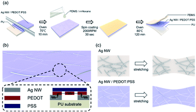
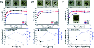
Fig. 1a illustrates the bar coated Ag NW/PEDOT:PSS hybrid ink (AP ink) on PU substrate and PDMS coating on top of AP electrode as protective layer. Fig. 1b shows the conductive bridge structure. Because the electrode was connected with both Ag NW and PEDOT:PSS, there were three possible electrical connections, namely Ag NW–Ag NW, Ag NW–PEDOT:PSS, and PEDOT:PSS–PEDOT:PSS. Fig. 1c shows schematics of electrical bridge effect mechanism. Because each Ag NW has a limited ability to stretch itself, an electrode made entirely of Ag NW may be readily disconnected from stretching, as shown in the upper schematic. In contrast, when PEDOT:PSS was incorporated into an Ag NW electrode, the PEDOT:PSS electrically interlinked the Ag NWs even when the electrode was stretched due to its great stretchability. Although the electrical property of PEDOT:PSS was weaker than that of Ag NW, Ag NW served as the primary current channel, and PEDOT:PSS served as an auxiliary electrode for stretchability. As a result, it can be said that Ag NW has a high electrical property and PEDOT:PSS has a high stretchability.The Ag NW/PEDOT:PSS ink was tested with various concentration ratios to optimize the electrode. Fig. 2 illustrates the optimization of the Ag NW/PEDOT:PSS electrode by varying the bar winding thickness, coating velocity and the concentration ratios. The optimization was done by comparing the transmittance and the sheet resistance of the variables. To determine the compatible process condition, we used Figure of Merits (FoM) (T10/Rsheet).34 where, T is transmittance and Rsheet is sheet resistance.
Fig. 2a shows the electrode bar coated at different winding thickness and it also shows the transmittance and the sheet resistance of the electrode. As the thickness of the bar winding increases, the transmittance decreases while the sheet resistance decreases. This implied that the coating was non-uniform with greater sheet resistances as the winding thickness decreased, and a winding thickness of 30 # exhibited high transmittance and lower sheet resistance with a larger FoM value. Fig. 2b shows the transmittance and sheet resistance properties of the electrode by varying the coating speed. When the coating speed was reduced, the transmittance decreased. This was due to the slow agglomeration of the solvent as the bar moved slower. But with higher coating velocity, there was an increase in sheet resistance. If the coating velocity was high, less time was needed to coat the ink on the substrate. As a result, the thickness of the electrode was reduced. The thinner film showed an increase in the sheet resistance and transmittance. However, it was observed that there was enough time to coat the ink on the substrate even if the velocity was slower. Thus, it can be said that the slower coating resulted in an abnormally thick electrode. And excessively thick electrode film reduced the sheet resistance and transmittance. In Fig. 2c, the ink ratios of Ag NW and PEDOT:PSS were varied at 10![[thin space (1/6-em)]](https://www.rsc.org/images/entities/char_2009.gif) :
:![[thin space (1/6-em)]](https://www.rsc.org/images/entities/char_2009.gif) 1, 20
1, 20![[thin space (1/6-em)]](https://www.rsc.org/images/entities/char_2009.gif) :
:![[thin space (1/6-em)]](https://www.rsc.org/images/entities/char_2009.gif) 1, and 30
1, and 30![[thin space (1/6-em)]](https://www.rsc.org/images/entities/char_2009.gif) :
:![[thin space (1/6-em)]](https://www.rsc.org/images/entities/char_2009.gif) 1, respectively. The concentration ratio of 30
1, respectively. The concentration ratio of 30![[thin space (1/6-em)]](https://www.rsc.org/images/entities/char_2009.gif) :
:![[thin space (1/6-em)]](https://www.rsc.org/images/entities/char_2009.gif) 1 showed excellent potential with an increase in transmittance and a decrease in sheet resistance.
1 showed excellent potential with an increase in transmittance and a decrease in sheet resistance.
The hydroscopic property of PEDOT:PSS allows humidity to be absorbed in the polymer. Then the PEDOT:PSS expanded, increasing the distance between PEDOTs. As a result, the average hopping distance increased while interactions decreased. The dipole moments of absorbed water can also influence the conductivity of PEDOT:PSS. As such, due to the influence of water, the electrical property of PEDOT:PSS may deteriorate.23,35 Also, moisture is the primary cause of silver corrosion. Therefore, water or moisture in the air can have an effect on the reliability of a silver electrode, such as a silver nano wire.26,36 In order to protect the electrode from the adverse effects of water, the PDMS was coated on the AP electrode. Because of the Cassie–Baxter state, the PDMS is hydrophobic due to the weak intermolecular interactions known as the London dispersion forces of the methyl group (–CH3) in PDMS and the helical molecular structure of PDMS that prohibits methyl groups from being on the same plane.37–39
In addition, Fig. 3 shows the image of DI water droplet on bare PU substrate, optimized AP electrode, and PDMS surface. The contact angle can determine the surface energy.40–42 The surface energy of film (γs) was calculated with Owens–Wendt method.43 The γs can be separated into the dispersion part (γds) and the polar part (γps) so that each part can be calculated from the contact angle of diiodomethane (DM) for disperse part and deionized water (DI) for polar part using below equations which well-known as Young equation (eqn (1))44 and Fowke's method (eqn (2)).42
γl![[thin space (1/6-em)]](https://www.rsc.org/images/entities/char_2009.gif) cos cos![[thin space (1/6-em)]](https://www.rsc.org/images/entities/char_2009.gif) θ = γs − γsl θ = γs − γsl
| (1) |
 | (2) |
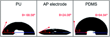 | ||
| Fig. 3 Photography of water droplet on a bare PU substrate, AP electrode on PU substrate, and PDMS on AP electrode. | ||
In these equations, γ is free energy, under scripts l and s are liquid and solid (film) against their vapor, sl is the interface between liquid and solid, and θ is contact angle. The superscripts d and p refer to the dispersion part and the polar part. By plugging eqn (2) into eqn (1), eqn (3) was obtained.
 | (3) |
Using the already known γdl, γpl, and γlv of DM and DI, the free energy of film can be calculated with contact angles. The results in Table 1 show that the AP electrode had the highest surface energy and PDMS had the lowest surface energy. High surface energy suggested that the AP electrode was highly absorbent and easily washed, limiting the possibility of using the AP electrode for diverse applications such as wearable devices. The hydrophobicity of PDMS allows it to successfully resist against moisture and allows it to be applied to wearable devices.45
| Surface | Diiodomethane contact angle [°] | Deionized water contact angle [°] | γds [mJ m−2] | γps [mJ m−2] | γs [mJ m−2] |
|---|---|---|---|---|---|
| PU | 30.99 | 68.58 | 40.728 | 7.499 | 48.227 |
| AP electrode | 29.64 | 24.08 | 38.054 | 32.402 | 70.456 |
| PDMS | 50.80 | 94.94 | 32.977 | 0.722 | 33.699 |
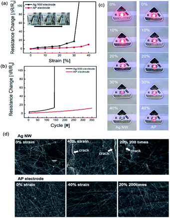
The AP electrode was subjected to stretching as illustrated in Fig. 4. To determine the endurance of the stretching electrode, resistance change ΔR = (R − R0)/R0 was calculated where, R is the measured resistance and R0 is the initial resistance. The resistance was tested in situ under stretched conditions. Fig. 4a shows the durability of Ag NW electrode and optimized AP electrode for the strain percentage. When the strain rate was increased up to 30%, the Ag NW electrode was broken due to the disconnection of Ag NW network and formed a crack on the electrode film. The AP electrode, on the other hand, was subjected to more than 40% strain, whereas the PEDOT:PSS supported the Ag NW by stretching without breaking the link with the nanowires. As shown in Fig. 4b, AP electrode showed highly enhanced endurance for 350 repetition cycles at a strain of 20%. At 20% strain rate repetition test, Ag NW was broken below 150 cycles. Fig. 4c depicts the enhanced stretching caused by the addition of PEDOT:PSS using a stretching jig and a light emitting diode (LED). When the strain percentage increased, the glowing LED brightness gradually decreased in both Ag NW and AP electrode. However, when stretched to 40%, the Ag NW electrode snapped compared to the AP electrode. The AP electrode was not broken at the higher stretch percentage because PEDOT:PSS helped in securing the bond between individual Ag NWs. The FE-SEM images shown in Fig. 4d clearly denoted the morphology of both the normal electrode and the stretched electrode. The FE-SEM image revealed cracks in the Ag NW electrode at 40% strain, demonstrating that the AP electrode was extremely stretchable, and it lasted at 20% stretch for 200 cycles.
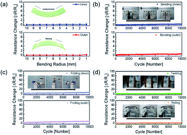
The mechanical fatigue test was carried out to further demonstrate the flexibility of the AP electrode in Fig. 5. If the mechanical tests on the Ag NW electrode were repeated, the Ag NW might be brittlely broken as the dislocation moved across the slip plane.46 The extremely flexible PEDOT:PSS in the AP electrode, on the other hand, still interlocked the Ag NW despite repeated fatigue tests, and the electrode demonstrated improved mechanical durability. Fig. 5a demonstrates that the outer and inner bending are subjected to tensile and compressive stress, respectively, resulting in no resistance change over the whole bending radius range of 10 mm to 1 mm. Even at 1 mm radius, there was no breaking of the electrodes under tensile and compressive stress, demonstrating that the electrode was exceptionally flexible. Furthermore, the outer and inner bending cycle tests at 2 mm radius for 10![[thin space (1/6-em)]](https://www.rsc.org/images/entities/char_2009.gif) 000 cycles revealed minimal resistive change, as illustrated in Fig. 5b. As illustrated in Fig. 5c and d, 10
000 cycles revealed minimal resistive change, as illustrated in Fig. 5b. As illustrated in Fig. 5c and d, 10![[thin space (1/6-em)]](https://www.rsc.org/images/entities/char_2009.gif) 000 cycles of folding and twisting of the AP electrode resulted in no change in resistance.
000 cycles of folding and twisting of the AP electrode resulted in no change in resistance.
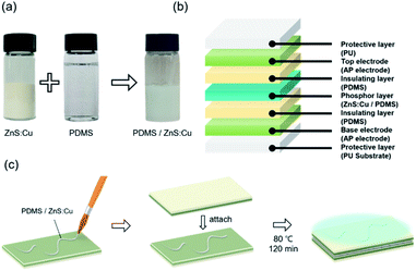
Electroluminescence (EL) devices were fabricated from the Ag NW/PEDOT:PSS electrode as shown in Fig. 6. When an AC voltage was introduced into the EL device composed of AP electrode and phosphor layer, electrons of phosphor layer get excited by the intensity of the electric field generating in the fluorescent layer. When the excited electrons returned to a stable state, the device emitted light. Fig. 6a shows the schematic image of ZnS:Cu and PDMS mixed in a weight ratio of 2![[thin space (1/6-em)]](https://www.rsc.org/images/entities/char_2009.gif) :
:![[thin space (1/6-em)]](https://www.rsc.org/images/entities/char_2009.gif) 1 respectively as a brush paintable phosphor ink. The fabrication and the number of layers of the EL devices are illustrated in Fig. 6b and c. The PDMS layer in the electrode worked as an insulating layer which protected the device from short circuit. Fig. 7a shows the phosphor ink brush painted on the AP electrode to show the canine image in both normal and stretched positions. We also made a wearable EL device which can be used as a safety vest or strap for a night worker or riders as shown in Fig. 7b. The EL devices were stretched at 20% for 300 times without losing their luminescence property, as shown in Fig. 7c. Despite the fact that the brightness decreased slightly as the number of repetitions increased, the EL device was still operational and easily distinguishable from the non-phosphor area.
1 respectively as a brush paintable phosphor ink. The fabrication and the number of layers of the EL devices are illustrated in Fig. 6b and c. The PDMS layer in the electrode worked as an insulating layer which protected the device from short circuit. Fig. 7a shows the phosphor ink brush painted on the AP electrode to show the canine image in both normal and stretched positions. We also made a wearable EL device which can be used as a safety vest or strap for a night worker or riders as shown in Fig. 7b. The EL devices were stretched at 20% for 300 times without losing their luminescence property, as shown in Fig. 7c. Despite the fact that the brightness decreased slightly as the number of repetitions increased, the EL device was still operational and easily distinguishable from the non-phosphor area.
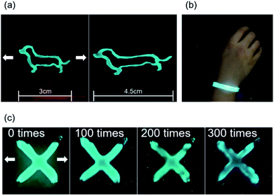 | ||
| Fig. 7 (a) Photography of brush painted EL device before and after stretching, (b) EL device wrapped around human wrist. (c) Stretching fatigue test with EL device. | ||
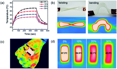
Fig. 8a shows the temperature profile of a TFH made of AP electrode with respect to strain rate. The TFH device attained 67.5 °C without strain and 45.5 °C with 30% stretch. This temperature change can be expressed by following equation:47
| V2/RA(Ts − Ti) = hc | (4) |
4. Conclusions
In this study, we demonstrated that mixing PEDOT:PSS into Ag NW enhanced the stretchability of Ag NW electrode by conductive bridge effect where the added PEDOT:PSS interlinked with the disconnected Ag NW network. The electrode was fabricated using bar coater with optimized AP ink on PU substrate and spin coater with PDMS/n-hexane mixture on the electrode surface. The optical, electrical, and mechanical properties of an electrode were investigated. The optimized AP electrode has 14.93 Ω sq−1. of sheet resistance and 88.6% of transmittance at 550 nm wavelength. The PDMS protective layer has a low surface energy and a hydrophobic property, which can protect the electrode from humidity-induced washing and corrosion. In the dynamic stretching test, the AP electrode endured over 40% stretch strain rate and 20% stretching repetition test for more than 350 times. These results showed enhanced endurance for stretching when compared with bare Ag NW electrodes. Other mechanical tests such as bending, folding, twisting, and rolling showed remarkable performances. For applications of electrode, the AP electrode was fabricated as EL devices and TFH devices. Various designed EL devices were created using brush paintable PDMS/ZnS:Cu phosphor ink. After the stretching cycle test, these devices performed well when stretched and worn 300 times. Moreover, TFH performed effectively in the twisted and bending states. These results demonstrated the potential of AP electrodes in a variety of stretchable or wearable applications.Conflicts of interest
There are no conflicts to declare.Acknowledgements
This work was supported by the Korea Basic Science Institute(KBSI) National Research Facilities & Equipment Center (NFEC) grant funded by the Korea government (Ministry of Education) (No. 2019R1A6C1010031), the Technology Innovation Program (or Industrial Strategic Technology Development Program) (20004934, Flexible touch sensor with high temperature durability over 130 C and transmittance over 88%) and Development of conductive adhesive material using self-assembly adhesion property of conductive particles for electrical connection of 20 m ultra fine pitch stretchable display funded by the Ministry of Trade, Industry & Energy (MOTIE, Korea) (20006479).Notes and references
- S. Huang, Y. Liu, Y. Zhao, Z. Ren and C. F. Guo, Adv. Funct. Mater., 2019, 29, 1805924 CrossRef.
- K. Xu, Y. Lu and K. Takei, Adv. Mater. Technol., 2019, 4, 1800628 CrossRef.
- T. Lv, Y. Yao, N. Li and T. Chen, Nano Today, 2016, 11, 644–660 CrossRef CAS.
- M. Wang, K. Guo and H. Cheng, IEEE Electron Device Lett., 2020, 41, 1118–1121 CAS.
- Y. Li, N. Wang, A. Yang, H. Ling and F. Yan, Adv. Electron. Mater., 2019, 5, 1900566 CrossRef CAS.
- Y. Zhou, H. Wang, J. He, K. Qi and B. Ding, Mater. Lett., 2019, 239, 1–4 CrossRef CAS.
- Z. Wang, L. Zhang, J. Liu and C. Li, ACS Appl. Mater. Interfaces, 2019, 11, 5316–5324 CrossRef CAS PubMed.
- J. Song, Y. Huang, J. Xiao, S. Wang, K. C. Hwang, H. C. Ko, D. H. Kim, M. P. Stoykovich and J. A. Rogers, J. Appl. Phys., 2009, 105, 123516 CrossRef.
- X. Li, S. Yu, L. Zhao, M. Wu and H. Dong, J. Mater. Sci.: Mater. Electron., 2020, 31, 8106–8115 CrossRef CAS.
- D. C. Kim, H. J. Shim, W. Lee, J. H. Koo and D. H. Kim, Adv. Mater., 2020, 32, 1902743 CrossRef CAS PubMed.
- H. S. Liu, B. C. Pan and G. S. Liou, Nanoscale, 2017, 9, 2633–2639 RSC.
- S. Hong, J. Lee, K. Do, M. Lee, J. H. Kim, S. Lee and D. H. Kim, Adv. Funct. Mater., 2017, 27, 1704353 CrossRef.
- K. S. Kim, Y. Zhao, H. Jang, S. Y. Lee, J. M. Kim, K. S. Kim, J. H. Ahn, P. Kim, J. Y. Choi and B. H. Hong, Nature, 2009, 457, 706–710 CrossRef CAS PubMed.
- Y. Wang, C. Zhu, R. Pfattner, H. Yan, L. Jin, S. Chen, F. Molina-Lopez, F. Lissel, J. Liu, N. I. Rabiah, Z. Chen, J. W. Chung, C. Linder, M. F. Toney, B. Murmann and Z. Bao, Sci. Adv., 2017, 3, 1602076 CrossRef PubMed.
- M. R. Benzigar, V. D. B. C. Dasireddy, X. Guan, T. Wu and G. Liu, Adv. Funct. Mater., 2020, 30, 2002993 CrossRef CAS.
- H. G. Im, J. Jang, Y. Jeon, J. Noh, J. Jin, J. Y. Lee and B. S. Bae, ACS Appl. Mater. Interfaces, 2020, 12, 56462–56469 CrossRef CAS PubMed.
- Y. F. Li, S. Y. Chou, P. Huang, C. Xiao, X. Liu, Y. Xie, F. Zhao, Y. Huang, J. Feng, H. Zhong, H. B. Sun and Q. Pei, Adv. Mater., 2019, 31, 1807516 CrossRef PubMed.
- K. K. Kim, I. H. Ha, P. Won, D. G. Seo, K. J. Cho and S. H. Ko, Nat. Commun., 2019, 10, 2582 CrossRef PubMed.
- Y. Sun, M. Chang, L. Meng, X. Wan, H. Gao, Y. Zhang, K. Zhao, Z. Sun, C. Li, S. Liu, H. Wang, J. Liang and Y. Chen, Nat. Electron., 2019, 2, 513–520 CrossRef CAS.
- Z. Ma, S. Kang, J. Ma, L. Shao, Y. Zhang, C. Liu, A. Wei, X. Xiang, L. Wei and J. Gu, ACS Nano, 2020, 14, 8368–8382 CrossRef CAS PubMed.
- X. Dong, P. Shi, L. Sun, J. Li, F. Qin, S. Xiong, T. Liu, X. Jiang and Y. Zhou, J. Mater. Chem. A, 2019, 7, 1989–1995 RSC.
- X. Zhang, V. A. Öberg, J. Du, J. Liu and E. M. J. Johansson, Energy Environ. Sci., 2018, 11, 354–364 RSC.
- M. Kuş and S. Okur, Sens. Actuators, B, 2009, 143, 177–181 CrossRef.
- E. Dauzon, Y. Lin, H. Faber, E. Yengel, X. Sallenave, C. Plesse, F. Goubard, A. Amassian and T. D. Anthopoulos, Adv. Funct. Mater., 2020, 30, 2001251 CrossRef CAS.
- J. E. Lim, S. M. Lee, S. S. Kim, T. W. Kim, H. W. Koo and H. K. Kim, Sci. Rep., 2017, 7, 14685 CrossRef PubMed.
- J. Jiu, J. Wang, T. Sugahara, S. Nagao, M. Nogi, H. Koga, K. Suganuma, M. Hara, E. Nakazawa and H. Uchida, RSC Adv., 2015, 5, 27657–27664 RSC.
- B. Zhang, Q. Dong, C. E. Korman, Z. Li and M. E. Zaghloul, Sci. Rep., 2013, 3, 1098 CrossRef.
- I. D. Johnston, D. K. McCluskey, C. K. L. Tan and M. C. Tracey, J. Micromech. Microeng., 2014, 24, 035017 CrossRef CAS.
- J. C. Lötters, W. Olthuis, P. H. Veltink and P. Bergveld, J. Micromech. Microeng., 1997, 7, 145–147 CrossRef.
- H. Wu, D. T. Chiu, J. R. Anderson, D. C. Duffy, G. M. Whitesides, J. C. McDonald and O. J. Schueller, Electrophoresis, 2000, 21, 27–40 CrossRef.
- R. M. Hakim, R. G. Olivier and H. St-Onge, IEEE Trans. Dielectr. Electr. Insul., 1977, 12, 360–370 Search PubMed.
- J. C. McDonald and G. M. Whitesides, Acc. Chem. Res., 2002, 35, 491–499 CrossRef CAS PubMed.
- J. Wang, C. Yan, K. J. Chee and P. S. Lee, Adv. Mater., 2015, 27, 2876–2882 CrossRef CAS PubMed.
- G. Haacke, J. Appl. Phys., 1976, 47, 4086–4089 CrossRef CAS.
- K. Kawano, R. Pacios, D. Poplavskyy, J. Nelson, D. D. C. Bradley and J. R. Durrant, Sol. Energy Mater. Sol. Cells, 2006, 90, 3520–3530 CrossRef CAS.
- T. E. Graedel, J. Electrochem. Soc., 1992, 139, 1963–1970 CrossRef CAS.
- M. J. Owen, Comments Inorg. Chem., 1988, 7, 195–213 CrossRef CAS.
- M. T. Khorasani, H. Mirzadeh and Z. Kermani, Appl. Surf. Sci., 2005, 242, 339–345 CrossRef CAS.
- V. Jankauskaite, P. Narmontas and A. Lazauskas, Coatings, 2019, 9, 36 CrossRef.
- M.-O. Goebel, J. Bachmann, S. K. Woche, W. R. Fischer and R. Horton, Soil Sci. Soc. Am. J., 2004, 68, 383–393 CrossRef CAS.
- D. Janssen, R. De Palma, S. Verlaak, P. Heremans and W. Dehaen, Thin Solid Films, 2006, 515, 1433–1438 CrossRef CAS.
- D. Y. Kwok and A. W. Neumann, Adv. Colloid Interface Sci., 1999, 81, 167–249 CrossRef CAS.
- D. K. Owens and R. C. Wendt, J. Appl. Polym. Sci., 1969, 13, 1741–1747 CrossRef CAS.
- H. L. Kornberg and H. A. Krebs, Nature, 1957, 180, 756–757 CrossRef PubMed.
- S. Wooh, N. Encinas, D. Vollmer and H. J. Butt, Adv. Mater., 2017, 29, 1604637 CrossRef PubMed.
- D. Kim, S. H. Kim, J. H. Kim, J. C. Lee, J. P. Ahn and S. W. Kim, Sci. Rep., 2017, 7, 45903 CrossRef CAS PubMed.
- S. H. Lim and H. K. Kim, Sci. Rep., 2020, 10, 1–13 CrossRef PubMed.
| This journal is © The Royal Society of Chemistry 2022 |

