 Open Access Article
Increasing anhydrous chromium chloride concentration in AlCl3–EMIC ionic liquid: a step towards non-hydrogen-embrittlement chromium electroplating
Duohua Xuab,
Jidan Lic,
Chunyuan Lianga,
Jincheng Liua,
Hongtao Wang *ab and
Guoping Lingd
aCenter for X-Mechanics, Zhejiang University, 310027 Hangzhou, China. E-mail: htw@zju.edu.cn
bZJU-Hangzhou Global Scientific and Technological Innovation Center, Zhejiang University, 311200 Hangzhou, China
cCapital Aerospace Machinery Corporation Limited, 100076 Beijing, China
dDepartment of Materials Science and Engineering, Zhejiang University, 310027 Hangzhou, China
First published on 12th January 2022
Abstract
Non-hydrogen-embrittlement chromium electroplating has wide applications in industry. Using an ionic liquid (AlCl3–1-ethyl-3-methyl-imidazolium chloride, AlCl3–EMIC) as the electrolyte provides a viable way for metal electrodeposition. However, the low solubility of anhydrous chromium chloride salt in acidic AlCl3–EMIC IL makes the electrodeposition process essentially impractical. We propose a new method for dissolving CrCl3 or CrCl2, which effectively increases the concentration of anhydrous chromium salts in AlCl3–EMIC IL. Moreover, we demonstrate for the first time that the electroless deposition of BCC Cr can be realized on an Al substrate using this solution, which indicates that the reduction potential of chromium ions in AlCl3–EMIC IL is more positive than that of aluminum ions. This proves the thermodynamic possibility of electroplating metallic Cr. Therefore, our work paves the way for the engineering application of electroplating non-hydrogen-embrittlement chromium.
1. Introduction
Electroplating hard chromium (EHC) is widely used in various industrial fields for its high hardness, excellent wear and corrosion resistance.1,2 However, the application of the general Cr(VI) electroplating process has been restricted by legislation because of its high toxicity and carcinogenicity.3 The Cr(III) electroplating process is less toxic, but it is difficult to obtain a coating with thickness above 10 μm, limiting its industrial application. Moreover, both processes are conducted in aqueous solution, resulting in the risk of hydrogen embrittlement to the substrate.4 High-strength steels are particularly prone to hydrogen embrittlement, as less than 1 ppm of hydrogen is sufficient to result in a dramatic degradation of their mechanical properties.5To completely avoid hydrogen embrittlement, an ionic liquid can be used as the electrolyte for metal electrodeposition. Meanwhile, the ionic liquid renders the electroplating process great advantages, such as a wide electrochemical window, high conductivity and non-volatility.6–8 Among synthesized ILs, AlCl3–EMIC is most widely used in electroplating metals and alloys.9–12 However, anhydrous CrCl3 is insoluble in acidic AlCl3–EMIC ionic liquid (acidic IL), e.g. molar ratio AlCl3![[thin space (1/6-em)]](https://www.rsc.org/images/entities/char_2009.gif) :
:![[thin space (1/6-em)]](https://www.rsc.org/images/entities/char_2009.gif) EMIC = 2
EMIC = 2![[thin space (1/6-em)]](https://www.rsc.org/images/entities/char_2009.gif) :
:![[thin space (1/6-em)]](https://www.rsc.org/images/entities/char_2009.gif) 1.13 High purity CrCl2 (99.99%) can be dissolved in an acidic IL.14 Since Cr(II) is unstable and easily oxidized to Cr(III), the surface of CrCl2 powder may have been partially oxidized during production and storage. This further lowers the chromium salts concentration in an acid IL.
1.13 High purity CrCl2 (99.99%) can be dissolved in an acidic IL.14 Since Cr(II) is unstable and easily oxidized to Cr(III), the surface of CrCl2 powder may have been partially oxidized during production and storage. This further lowers the chromium salts concentration in an acid IL.
An alternative method is to use hydrated Cr(III) salt and EMIC for electroplating.4,15,16 In this way, the electrolyte is essentially an aqueous solution so that hydrogen embrittlement cannot be completely avoided. On the other hand, anhydrous chromium salts, including both CrCl3 and CrCl2, can be dissolved in alkaline AlCl3–EMIC IL (alkaline IL).13 But chromium ions cannot be reduced to metallic Cr for the stable structure of the chromium complex ion in alkaline IL.17
Here, we proposed a novel method to dissolve anhydrous chromium salt in order to improve chromium chloride concentration in AlCl3–EMIC IL, which lays a solid foundation for preparing solution for electroplating metal Cr. Moreover, we demonstrate that the electroless deposition of Cr on Al substrate can be realized, which proves the thermodynamic feasibility of electroplating metallic Cr in the obtained solution.
2. Experimental
2.1 Preparation of ionic liquid
The anhydrous AlCl3 powder (99.99%, Alfa Aesar) was slowly added to EMIC until the molar ratio of AlCl3 and EMIC is 2![[thin space (1/6-em)]](https://www.rsc.org/images/entities/char_2009.gif) :
:![[thin space (1/6-em)]](https://www.rsc.org/images/entities/char_2009.gif) 1. During the mixture process, the temperature is kept below 70 °C. After stirring for 24 h, the anhydrous AlCl3 powder is fully dissolved. Aluminum wires with purity 99.99% are immersed in the ILs for at least 48 h at 50 °C to remove impurities. The processed acid AlCl3–EMIC IL (acid IL) then becomes colorless and transparent. In the same way, the molar ratio of AlCl3 to EMIC was adjusted to 0.8
1. During the mixture process, the temperature is kept below 70 °C. After stirring for 24 h, the anhydrous AlCl3 powder is fully dissolved. Aluminum wires with purity 99.99% are immersed in the ILs for at least 48 h at 50 °C to remove impurities. The processed acid AlCl3–EMIC IL (acid IL) then becomes colorless and transparent. In the same way, the molar ratio of AlCl3 to EMIC was adjusted to 0.8![[thin space (1/6-em)]](https://www.rsc.org/images/entities/char_2009.gif) :
:![[thin space (1/6-em)]](https://www.rsc.org/images/entities/char_2009.gif) 1, and colorless and transparent alkaline AlCl3–EMIC IL (alkaline IL) is obtained after purification.
1, and colorless and transparent alkaline AlCl3–EMIC IL (alkaline IL) is obtained after purification.
2.2 Dissolution of chromium salt
In our experiments, only CrCl2 with purity above 99.99% can be dissolved in the prepared acid IL. Even though, the actual solubility is still low since Cr2+ is easily oxidized to Cr3+. To overcome the above difficulty, we propose a novel method so that CrCl3 or CrCl2 with lower impurity can be used and the process prevents any possible Cr2+ oxidation. It is noted that CrCl3 or CrCl2 with impurity 99.9% (Alfa Aesar) can be dissolved in alkaline IL. The key step is the following refining process by immersing Al wires in the prepared solution, which greatly increases the chromium salt concentration. The last step is to add acidic IL until the solution becomes colorless and transparent. The chromium salt concentration is 0.45 mol L−1 in the solution.2.3 Sample preparation
The Al and Cr substrate with purity 99.99% are used and cut into samples with size of 15 mm × 30 mm × 1 mm. After mechanical polishing, all samples are immersed in ethanol and cleaned ultrasonically for 5 minutes. After dried with nitrogen, the samples are sealed with tape to set aside a 10 mm × 10 mm area for further research. The Al substrates are subjected to anodic etching pretreatments to remove surface oxide, which helps improve the bond between Al substrate and Cr coating. The Al plates are used as both the anode and the cathode during the anodic etching process. The acid IL is used as the electrolyte. The duration is 2 min and the current density is set to 30 mA cm−2. Similarly, the Cr plate is subjected to pretreatment of linear scanning voltammetry (LSV) before the open circuit potential (OCP) test. For LSV test, the Al plate is used as counter electrode and Cr plate is used as working electrode. The aluminum wire immersed in a porous ceramic glass tube filled with acid IL is used as a reference electrode. Scan rate is 10 mV s−1.2.4 Characterization methods
The absorption spectrum of the prepared solution is tested by a spectrometer (Model ND-1000, Nanodrop Company). The morphology of the Cr deposit is characterized by a scanning electron microscope (SEM) equipped an energy dispersive spectrometer (Model SU-8010, HITACHI Company). The three-dimensional profile information including deposit thickness and roughness are tested with an optical profilometer (Model NT9100, Veeco Company). The composition is analyzed by the inductively coupled plasma and atomic emission spectrometer (ICP-AES, Model 730-ES, Varian Company). The phase is identified using the graze incidence X-ray diffraction (GI-XRD, Model SmartLab, Rigaku Company). The microstructure is characterized by a transmission electron microscope operated at 200 kV (TEM, Model JEM-2100, JEOL Company). The open circuit potential test is performed during the displacement deposition process. For cyclic voltammetry (CV) test, the Al plate is used as the counter electrode. The working electrode is a glassy carbon electrode. The aluminum wire immersed in a porous ceramic glass tube filled with acid IL is used as a reference electrode. Scan rate is 10 mV s−1. All electrochemical tests are performed using an electrochemical workstation (Model CHI660e, Chenhua Company). We note that the AlCl3–EMIC IL is sensitive to water. The solution preparation, the anode etching and electroless deposition experiments are carried out in a glove box filled with argon, in which the oxygen and water content are maintained below 1 ppm.3. Results and discussion
3.1 Discussion on the chromium salt dissolution process
By gradually adding acidic IL to the alkaline IL containing anhydrous CrCl2 (99.9%), the transparent blue-green alkaline IL becomes turbid at first and turns to be clear. We note that some red precipitate at the bottom of the beaker is identified to be CrCl3, indicating CrCl3 is insoluble in acidic IL. This is due to the partially oxidation of CrCl2 to CrCl3 before dissolution. Once the alkaline IL containing CrCl2 is refined by the aluminum wire, no red precipitate can be observed with the addition of acidic IL. With the addition of acidic IL, the turbid solution gradually becomes clear, indicating the formation of Cr(II) complex in the acidic IL. In order to prevent Cr(II) from being oxidized into Cr(III) by the residue water or oxygen within glove box, we use pure metallic Cr to refine the solution. The prepared solution is colorless and transparent after refinement. This shows that the metallic Cr preferentially loses electrons to prevent Cr(II) from being oxidized.3.2 Discussion on Al refining effect
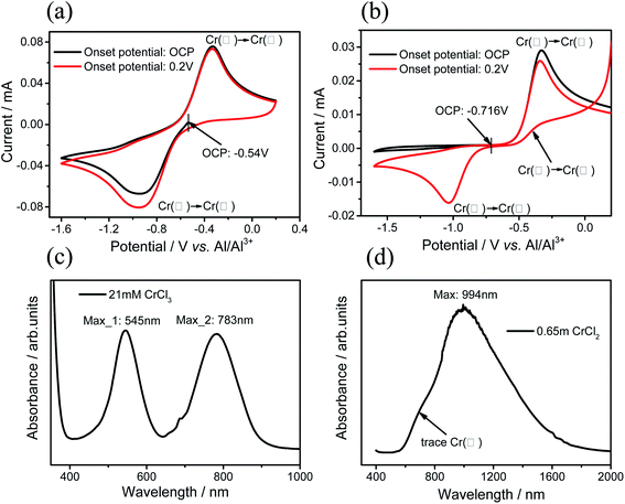
The refining step plays a key role in dissolving anhydrous chromium salt in AlCl3–EMIC IL. The alkaline IL dissolving Cr(III) presents blue-violet color, while the alkaline IL dissolving Cr(II) presents green color.15 To unveil the mechanism of the refining process, the alkaline IL solution dissolving CrCl3 is prepared. As expected, the solution is clear and shows blue-violet color. The solution is refined by adding Al wires and kept at 50 °C for a week. The color gradually changes to green, indicating the reduction of Cr(III) to Cr(II). Meanwhile, the appearance of the Al wires becomes dark and roughened.For alkaline IL dissolving Cr(III), the CV curves shows a pair of redox peaks when sweeping from the OCP potential −0.54 V or 0.2 V (Fig. 1(a)). The reduction peak around −1.0 V reveals that Cr(III) is reduced to Cr(II), while the oxidation peak around −0.4 V indicates that Cr(II) is oxidized to Cr(III). After refining, the reduction peak disappears and only the oxidation peak shows up when sweeping from the OCP at −0.716 V (Fig. 1(b)), which should be consistent with the CV result of solution dissolving only high purity CrCl2 (99.99% in purity) in alkaline IL. The comparison shows that Cr(III) is reduced to Cr(II) after the Al refining step.
In order to verify whether the reduction reaction is complete, the absorption spectrum study has been carried out. It is known that the spectra are characterized by the two absorption peaks at the wavelengths of 545 nm and 783 nm for the alkaline IL dissolving Cr(III) and one absorption peak at the wavelengths of 994 nm for the alkaline IL dissolving Cr(II).15 Fig. 1(c) and (d) show the absorption spectra from the alkaline IL dissolving Cr(III) and the refined solution, respectively. The observation is consistent with the results from ref. 15, revealing that nearly all Cr(III) is reduced to Cr(II) after the refining step. Close observation reveals that a small superposed peak shows up around 700 nm in Fig. 1(d), which may indicate the trace Cr(III) in the refined solution. Nevertheless, all experiments show that aluminum can effectively reduce Cr(III) to Cr(II) in alkaline AlCl3–EMIC IL. We note that the Cr electroplating requires the AlCl3–EMIC IL to be acidic. For this purpose, the acid IL is added until the solution becomes colorless and transparent. The final Cr(II) salt concentration is 0.45 mol L−1 in the acid solution.
The early study shows that chromium ions cannot be reduced to metallic Cr for the stable structure of the chromium complex ion in alkaline IL.17 As comparison, the electroless deposition has been performed to explore the possibility of Cr electroplating using the prepared solution by the proposed two-step method. Because the standard electrode potential of Al is more negative than that of Cr, once Al is immersed in prepared solution, its surface may undergo a displacement reaction.
In order to completely remove the oxide film on Cr substrate to observe stable OCP potential, the LSV test of Cr substrate was conducted as shown in Fig. 2(a). It can be seen that after the first two scans, the initial oxidation potential of the third and fourth scan shift negatively, indicating that the oxide film on Cr substrate is largely destroyed, which makes Cr substrate easier to oxidize. The rapid decrease of the current density in LSV curve indicates Cr passivation. After passivation, a lavender film is observed on Cr surface. The film is unstable and disappeared after being immersed in IL for 1 min when the applied potential is removed.
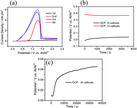 | ||
| Fig. 2 (a) LSV curve of Cr electrode, scan rate: 10 mV s−1, (b) OCP of Cr cathode and Al cathode at 25 °C for 1 h. (c) OCP of Al cathode at 60 °C for 10 h in IL. | ||
The OCP test is carried out to see if there is any reaction on Al surface without bias. As shown in Fig. 2(b), the OCP potential of the Cr working electrode is stable at 0.366 V and Al working electrode is about 0.039 V when performed at 23 °C. When performed at 60 °C, the OCP potential of Al working electrode is about 0.065 V (Fig. 2(c)). The slowly rising potential indicates the beginning of the displacement reaction of Cr on the Al substrate surface. The OCP potential of the Al electrode is lower than that of Cr electrode, which may come from both the Cr deposits and the Al substrate for the less-dense microstructures.
3.3 Characterization of the Cr coating
In the experiment, we find that anodic pre-treatment is critical for improving the bonding force between Cr coating and Al substrate. If Al substrate is directly immersed in IL to deposit after mechanical polishing, the Cr coating is easily to peel off when the Cr-plated sample is placed in the atmosphere for a period of time. If Al substrate is pre-treated by anodic etching before deposition, the Cr coating can be well combined with Al substrate after long-term storage in the atmosphere. This shows that the anode etching pre-treatment greatly improves the bonding force between the Cr coating and the Al substrate. On the one hand, the oxide film on the surface of Al substrate is completely removed. On the other hand, ionic liquid does not contain water and prevent the surface of active Al substrate from being oxidized again.Fig. 3 shows the surface morphology of the deposits. After immersing Al plate in prepared solution for 1 hour at 23 °C, particles with size about a few microns are found on the surface (Fig. 3(a)) and a large area of Al substrate is exposed. After 90 h, the surface is uniformly covered by continuous metallic coating (Fig. 3(b)). The EDS result shows that the Cr content is 97 at% and the rest is Al. The presence of a small amount of Al may be due to the Al substrate. A close observation shows that the deposit is an aggregate of particles with size 1–2 μm (Fig. 3(c)). Each particle is composed of smaller grains with size about 50 nm (Fig. 3(d)).
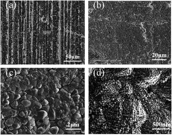 | ||
| Fig. 3 SEM images of Cr deposits coated in Al substrate in case (a) immersing time: 1 h, at 23 °C, and case (b)–(d) immersion time: 90 h, at 23 °C, at different magnifications. | ||
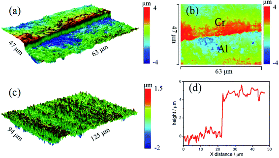
In order to determine the phase structure of the coating, GI-XRD tests are carried out on deposits. Besides the strong diffraction peaks of Al substrate, the diffraction peaks of metallic Cr are also detected (Fig. 4), which corresponds to (110), (200) and (211) crystal planes. The surface profile information of deposits was shown in Fig. 5. The thickness of the deposits is about 4 μm, and the roughness Ra is about 180 nm. Furthermore, the deposition rate is increased at elevated temperature. For example, the coating thickness reaches about 6–7 μm after 10 hours at 50 °C.
The TEM characterization further confirms the phase of the coating is body-centered cubic Cr by the selected area electron diffraction (SAED) pattern. The diffraction rings come from (110), (200), (211) and (220) lattice planes of BCC Cr, as indicated in Fig. 6(a). Fig. 6(c) and (d) show the high-resolution TEM images of the deposits. The interplanar spacing is measured to be 0.2 nm, which corresponds to the Cr(110) crystal plane. No Al phase can be found by TEM. The Cr content is measured to be 94 at% by ICP. It can be concluded that the deposit is mainly metallic chromium. The small amount of Al is probably introduced from the Al substrate during ICP sample preparation. These results indicate that the reduction potential of chromium ions is more positive than that of aluminum ions. In case of electrodeposition, chromium ions can be preferentially discharged at the cathode from a thermodynamic point of view.
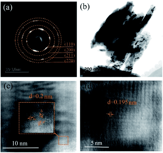 | ||
| Fig. 6 TEM images of the Al substrate including (a) SAED patterns, (b) low-magnification bright-field TEM image, (c) and (d) high-magnification TEM image. | ||
4 Conclusions
This work proposes a new method for dissolving anhydrous CrCl3 or CrCl2, which effectively improves the solubility of chromium salts in AlCl3–EMIC IL. The electroless deposition of Cr on Al surface in AlCl3–EMIC IL has been demonstrated using the solution. The deposited film uniformly covered the Al substrate with a thickness 4–6 μm. The phase is identified to be BCC Cr by XRD and TEM. The above results firmly prove the thermodynamic feasibility of electroplating metallic Cr in obtained solution. We believe that electroplating non-hydrogen embrittlement metallic Cr from such solution has great potential in engineering applications.Author contributions
H. Wang and G. Ling designed the project. Duohua Xu and Jincheng Liu contributed to experiments and data analysis. Jidan Li contributed to discussions during the work. Chunyuan Liang conducted TEM observations and data analysis. All authors wrote the paper and provided feedback on the paper.Conflicts of interest
There are no conflicts to declare.Acknowledgements
This research was funded by the Natural Science Foundation of China (Grant No. 11725210).References
- D. D. Pianta, J. Frayret, C. Gleyzes, C. Cugnet, J. C. Dupin and I. L. Hecho, Determination of the chromium(III) reduction mechanism during chromium electroplating, Electrochim. Acta, 2018, 284, 234–241 CrossRef.
- S. Eugénio, C. M. Rangel, R. Vilar and S. Quaresma, Electrochemical aspects of black chromium electrodeposition from 1-butyl-3-methylimidazolium tetrafluoroborate ionic liquid, Electrochim. Acta, 2011, 56, 10347–10352 CrossRef.
- E. L. Smith, A. P. Abbott and K. S. Ryder, Deep eutectic solvents (DESs) and their applications, Chem. Rev., 2014, 114, 11060–11082 CrossRef CAS PubMed.
- L. Sun and J. F. Brennecke, Characterization of imidazolium chloride ionic liquids plus trivalent chromium chloride for chromium electroplating, Ind. Eng. Chem. Res., 2015, 54, 150422160835004 Search PubMed.
- B. Sun, W. Lu, B. Gault, R. Ding and D. Raabe, Chemical heterogeneity enhances hydrogen resistance in high-strength steels, Nat. Mater., 2021, 20, 1629–1634 CrossRef CAS PubMed.
- N. V. Plechkova and K. R. Seddon, Applications of ionic liquids in the chemical industry, Chem. Soc. Rev., 2008, 37, 123–150 RSC.
- A. P. Abbott, G. Frisch and K. S. Ryder, Electroplating using ionic liquids, Annu. Rev. Mater. Res., 2013, 43, 335–358 CrossRef CAS.
- M. Armand, F. Endres, D. R. MacFarlane, H. Ohno and B. Scrosati, Ionic-liquid materials for the electrochemical challenges of the future, Nat. Mater., 2009, 8, 621–629 CrossRef CAS PubMed.
- Y. Wang, R. G. Reddy and R. Wang, Dendrite-free Al recycling via electrodeposition using ionic liquid electrolytes: The effects of deposition temperature and cathode surface roughness, J. Cleaner Prod., 2020, 287, 125043 CrossRef.
- J. Tang and K. Azumi, Optimization of pulsed electrodeposition of aluminum from AlCl3-1-ethyl-3-methylimidazolium chloride ionic liquid, Electrochim. Acta, 2011, 56, 1130–1137 CrossRef CAS.
- J. Ding, B. Xu and G. Ling, Al–Mn coating electrodeposited from ionic liquid on NdFeB magnet with high hardness and corrosion resistance, Appl. Surf. Sci., 2014, 305, 309–313 CrossRef CAS.
- Y. Sato and K. Azumi, Al–Zn co-electrodeposition by a double counter electrode electrodeposition system from an AlCl3–1-ethyl-3-methylimidazolium chloride ionic liquid bath, Surf. Coat. Technol., 2016, 286, 256–261 CrossRef CAS.
- T. J. Melton, J. Joyce, J. T. Maloy, J. A. Boon and J. S. Wilkes, Electrochemical studies of sodium chloride as a Lewis Buffer for room temperature chloroaluminate molten salts, J. Electrochem. Soc., 1990, 137, 3865 CrossRef CAS.
- A. Nishikata and T. Tsuru, Electrodeposition of aluminum-chromium alloys from AlCl3-BPC melt and its corrosion and high temperature oxidation behaviors, Electrochim. Acta, 1997, 42(15), 2347–2354 CrossRef.
- A. P. Abbott and K. J. Mckenzie, Application of ionic liquids to the electrodeposition of metals, Phys. Chem. Chem. Phys., 2006, 8, 4265–4279 RSC.
- A. P. Abbott, A. A. Al-Barzinjy, P. D. Abbott, G. Frisch, R. C. Harris, J. Hartley and K. S. Ryder, Speciation, physical and electrolytic properties of eutectic mixtures based on CrCl3·6H2O and urea, Phys. Chem. Chem. Phys., 2014, 16, 9047–9055 RSC.
- J. S. Y. Liu, P. Y. Chen, I. W. Sun and C. L. Hussey, Electrochemical studies of chromium(III) and chromium(II) chloride complexes in basic aluminum chloride-1-methyl-3-ethylimidazolium chloride room temperature molten salts, J. Electrochem. Soc., 1997, 144(7), 2388–2392 CrossRef CAS.
| This journal is © The Royal Society of Chemistry 2022 |

