 Open Access Article
Cross-linked β-CD-CMC as an effective aqueous binder for silicon-based anodes in rechargeable lithium-ion batteries†
Hao-wen Jianga,
Yan Yanga,
Yi-ming Niea,
Zhi-fang Sua,
Yun-fei Longa,
Yan-xuan Wen ab and
Jing Su
 *a
*a
aSchool of Chemistry and Chemical Engineering, Guangxi University, Nanning, Guangxi, China. E-mail: sujing@gxu.edu.cn
bGuangxi Key Laboratory of Processing for Non-ferrous Metallic and Featured Materials, Guangxi University, Nanning, China
First published on 18th February 2022
Abstract
As a non-active material component, the binder can effectively maintain the integrity of battery electrodes. In this work, based on the inspired structure of fishing nets, a three-dimensional mesh adhesive using widely sourced raw materials CMC and β-CD was designed. These cross-linked cyclodextrins have the advantage of dispersing the stress at the anchor point and moderating the significant volume changes of the Si anode. The Si/β-CD-CMC electrode maintains a reversible capacity of 1702 mA h g−1 even after 200 cycles at a high current of 0.5C. This work represents a significant step forward in Si anode binders and enables the cross-linked cyclodextrins to have potential applications in energy storage systems.
1. Introduction
Due to the rapid development of electric vehicles (EVS) and hybrid electric vehicles (HEV), higher requirements are placed on the energy density of lithium-ion batteries (LIBS).1–3 The theoretical capacity of silicon is as high as 4200 mA h g−1, which is about 10 times higher than that of traditional graphite. It is considered a promising anode material for lithium-ion batteries. However, the significant volume changes in Si electrode materials during charging and discharging can rapidly degrade capacity.4 Aimed at preventing electron transfer discontinuities caused by cracking and flaking of the pole pieces, researchers need to not only reduce the volume expansion by nanosizing,5 morphology control,6 alloying,7 and carbon cladding,8 but also improve the mechanical stability between the active particles and the collector.9 Although much research has been carried out on Si electrodes, it is too early to expect them to be commercialized.In traditional LIBs research, it is often assumed that the binder is one of the non-functional components.10,11 The role of the binder is to connect conductive additives and bond them to the surface of the collector. However, the widely-used PVDF binders form weak connections mainly through van der Waals interactions and do not provide a strong enough bond for Si particles.12 To mitigate this problem, researchers have used reactive groups such as hydroxyl and carboxyl groups to form hydrogen or chemical bonds stronger than van der Waals forces.13,14 Some raw materials with reactive groups such as carboxymethyl cellulose (CMC),15 guar gum,16 carrageenan,17 chitosan,18 and polyacrylic acid (PAA)19 have been investigated. Unfortunately, most of the studied binder systems have only a one-dimensional linear structure, resulting in a unidirectional binding force. Some three-dimensional cross-linked polymers, including PAA-CMC,20 CMC-CA,21 cross-linked dextrins,22 and pectin/PAA,23 can generate multi-point forces with Si, disperse stress in different directions and have better strain resistance.
β-Cyclodextrin is produced by the cyclodextrin glucosyltransferase produced by starch, which is a 7-membered sugar macrocycle with monomeric glucose units.24 The three-dimensional structure of the β-cyclodextrin molecule has a cylindrical shape with one large end and one small end. The small port is made up of 7 primary hydroxyl groups on C6, and the large port is composed of 14 secondary hydroxyl groups on C2 and C3. It has attracted increasing interest as an alternative binder for electrodes due to its rich hydroxyl group.25 Jeong et al. have synthesized hyperbranched β-cyclodextrin polymers as binders. Due to the reticular structure of β-CDp that allows multi-dimensional contact with Si, the binder had kept the stability of the electrode structure effectively. The specific capacity of the Si anode was 1471 mA h g−1 after 200 cycles.26 Subsequently, the group selected β-CDp and adamantine (AD) as the host-guest pair and designed the host-guest complex by “dynamic cross-linking”, which produced excellent cycling performance with a capacity retention of 90% after 150 cycles.27 The introduction of quaternary ammonium cations in β-CD by Zeng et al. helped alleviate the shuttle of polysulfides and the volume change in lithium-sulfur batteries.28
Carboxymethyl cellulose is the first natural binder to receive attention and is widely used in industrial production in the binder of silicon-based materials.29 The CMC strongly interacts with the oxide layer on the Si surface and thus binds the Si particles tightly together. On the other hand, the CMC can strongly interact with the collector (copper foil).30 As a green binder, CMC is directly soluble in water and has excellent compatibility with electrolytes. In contrast, PVDF requires expensive, toxic, flammable and explosive N-methylpyrrolidone as a solvent.31 The condensation reaction of CMC with silicon oxides on the surface of Si particles was further studied by FTIR spectroscopy by Hochgatterer et al.32 Li et al. demonstrated that CMC could modulate the formation of SEI layers on the surface of Si particles, thereby improving the capacity retention and cycle life.30 Bride et al. prepared different Si/C/CMC by changing the formula of the composite material. Use various characterization techniques to understand the specific role of CMC binders better. And to demonstrate that this binder can be successfully extended to other materials (tin, germanium, antimony).33 However, as CMC is a straight-chain polymer, it will slip during the violent volume expansion of Si anode, resulting in the detachment of the electrode material from the collector fluid and leading to irreversible capacity degradation. On the other hand, CMC's high brittleness and low elongation could not suffer the volume change of Si anode, which destroys the entire structure of the composite material.
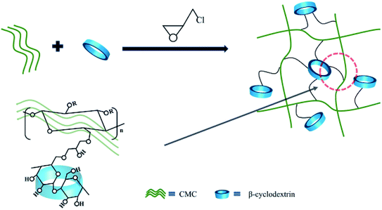
This work has designed a three-dimensional binder with fishing nets structure using the widely sourced raw materials CMC and β-CD as raw materials. The linear natural polymer CMC forms a dense network of “fishing nets”. Due to its abundant hydroxyl groups, β-CD is suitable as an anchor point for the network. The advantage of this strategy is that it can disperse the stress at the anchor point. We have systematically investigated the structure, stability, adhesion and electrochemical properties of silicon-based electrodes. The overall results show that the dense three-dimensional network structure effectively prevents the molecular chains from slipping off the Si surface and mechanically maintains the integrity of the silicon-based electrodes. Renewable, low-cost, structurally and performance-improved binders from cellulose hold great promise for the new era of LIBs.
2. Experimental
2.1. Electrode preparation
Commercial silicon (Si) pellets were purchased from Shanghai ST-NANO Science & Technology Co., Ltd. The average particle size of silicon is 100 nm and is used directly without any treatment. β-Cyclodextrin and epichlorohydrin were purchased from Tianjin Damao Chemical Reagent Factory. CMC is purchased from Sinopharm Chemical Reagent Co., Ltd. The electrolyte composed of Fluoroethylene Carbonate (FEC) and lithium hexafluorophosphate solution (1 M LiPF6 in EC/DEC = 50/50 (v/v)) were purchased from Suzhou DuoDuo Chemical Technology Co., Ltd.The synthesis process of β-CD-CMC binder is shown in Fig. 1. Briefly, a lower concentration of sodium hydroxide solution is prepared, and then a proportion of β-cyclodextrin and carboxymethyl cellulose are added in turn, respectively. The mixture is left to stand at room temperature until it is completely dissolved and the air bubbles are removed by standing or ultrasound. The solution after removal of air bubbles is added with stirring to an excess of epichlorohydrin and stirred rapidly at room temperature for 30 min. The temperature was then raised to 30 °C and keep stirring continued for 2 h. After which stirring stopped, the temperature was raised to 60 °C and hold for 10 h. The product is freeze–dried and ground.34
The silicon-based electrode plates were prepared as follows. The silica nanopowder was mixed with acetylene black and binder in a weight ratio of 6![[thin space (1/6-em)]](https://www.rsc.org/images/entities/char_2009.gif) :
:![[thin space (1/6-em)]](https://www.rsc.org/images/entities/char_2009.gif) 2
2![[thin space (1/6-em)]](https://www.rsc.org/images/entities/char_2009.gif) :
:![[thin space (1/6-em)]](https://www.rsc.org/images/entities/char_2009.gif) 2. The mixture is vigorously stirred to obtain a homogeneous slurry with water as the medium then applied to the current collector (copper foil) with a scalpel. The spacing between the scalpel and the copper foil was controlled to 90 μm when coating. The film was pre-dried in an oven at 60 °C for 6 h and then dried overnight at 120 °C under vacuum for solvent movement. The dry film was cut into circular pole pieces of 14 mm diameter for cell assembly.35
2. The mixture is vigorously stirred to obtain a homogeneous slurry with water as the medium then applied to the current collector (copper foil) with a scalpel. The spacing between the scalpel and the copper foil was controlled to 90 μm when coating. The film was pre-dried in an oven at 60 °C for 6 h and then dried overnight at 120 °C under vacuum for solvent movement. The dry film was cut into circular pole pieces of 14 mm diameter for cell assembly.35
2.2. Characterization and electrochemical testing
The coin cell (CR2032) was assembled in a glove box filled with argon gas (water and oxygen content less than or equal to 0.1 ppm). A thin sheet of pure lithium was used as both the counter electrode and reference electrode. The electrolyte was a lithium hexafluorophosphate solution (1 M LiPF6 in EC/DEC = 50/50 (v/v) with 10% FEC). The diaphragm is a microporous polypropylene membrane (Celgard 2400, USA). The sealer, purchased from Shenzhen Kejing Co., Ltd, is used with a pressure setting of 1000 psi. The assembled battery was tested for charging and discharging using the NEWARE system in a voltage window of 0.01–1.0 V vs. Li/Li+ at the constant charge–discharge current. Cyclic voltammetry (CV) and electrochemical impedance spectroscopy (EIS) testing was conducted using an electrochemical workstation manufactured by Gamry, USA. The CV test has a scan voltage range of 0.1 to 1.5 V and a scan rate of 0.1 mV s−1. EIS test is carried out at frequencies between 0.1 Hz and 100 kHz with an AC voltage of 5 mV. The theoretical capacity of Si was 4200 mA h g−1. The cycling performance was tested at 0.5C, with the first three cycles as a lower current of 0.1C for activation. The surface of the electrode poles before and after cycling was observed using an S3400N Scanning Electron Microscope (SEM) manufactured by COXEM. The X-ray diffraction tests of the samples were undertaken with a German Bruker D8 Advance X-ray diffractometer using Cu Kα radiation (λ = 1.5406 Å). Test conditions are 20° min−1 stroke rate and 10–80° scan range. The chemical composition and functional groups were determined using Fourier Transform Infrared Spectroscopy (FTIR) in the wavelength range of 4000 cm−1 to 500 cm−1. Thermogravimetric analysis (TG) is performed in air at a ramp rate of 10 °C min−1, from room temperature to 600 °C.2.3. Mechanical property testing
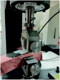
Peeling tests were performed through the Instron micro force tester. Peeled samples cut into appropriate sizes. The coated side of the electrode sample has been adhered with tape adhesive. To ensure that the same force is applied to each sample, a 200 g weight is used to apply the initial pressure. The equipment used for the experiment is shown in Fig. 2. The peeling speed was 10 mm min−1.3. Results and discussion
3.1. Evidence of cross-linking products
In order to demonstrate the presence of cross-linking, the binder samples prepared in different proportions were characterized by FTIR compared to a simple mixture of β-CD and CMC in a 1![[thin space (1/6-em)]](https://www.rsc.org/images/entities/char_2009.gif) :
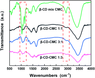
:![[thin space (1/6-em)]](https://www.rsc.org/images/entities/char_2009.gif) 1 mass ratio, the results of which are shown in Fig. 3. A comparison of three different ratios of β-cyclodextrin polymers shows that the absorption peaks of the polymers almost match, indicating that the β-CD-CMCs obtained by changing the feeding ratio have the similar structural composition. A comparison of the performance of β-CD-CMC prepared in three different ratios as Si-based electrode binders is shown in Fig. S1.† The absorption peak at a wavelength of 3403 cm−1 can be attributed to the asymmetric stretching vibration of –O–H. The peak at 2920 cm−1 corresponds to the antisymmetric stretching vibrational absorption peak of –CH2. It is noteworthy that the absorption peak at 2920 cm−1 of β-CD-CMC broadens for the grafted sample splits into two peaks. This phenomenon is due to the grafting of epichlorohydrin, resulting in introducing a new –CH2 group. The absorption peaks at 1422 cm−1 and 945 cm−1 are from α-1,4-glycosidic bond skeleton vibrations. The cliffs at 1025–1157 cm−1 are the stretching vibrations of C–O within the β-CD cavity and the absorption peaks of the stretching vibrations of C–O–C.36 The absorption peak at 1600 cm−1 is derived from the C
1 mass ratio, the results of which are shown in Fig. 3. A comparison of three different ratios of β-cyclodextrin polymers shows that the absorption peaks of the polymers almost match, indicating that the β-CD-CMCs obtained by changing the feeding ratio have the similar structural composition. A comparison of the performance of β-CD-CMC prepared in three different ratios as Si-based electrode binders is shown in Fig. S1.† The absorption peak at a wavelength of 3403 cm−1 can be attributed to the asymmetric stretching vibration of –O–H. The peak at 2920 cm−1 corresponds to the antisymmetric stretching vibrational absorption peak of –CH2. It is noteworthy that the absorption peak at 2920 cm−1 of β-CD-CMC broadens for the grafted sample splits into two peaks. This phenomenon is due to the grafting of epichlorohydrin, resulting in introducing a new –CH2 group. The absorption peaks at 1422 cm−1 and 945 cm−1 are from α-1,4-glycosidic bond skeleton vibrations. The cliffs at 1025–1157 cm−1 are the stretching vibrations of C–O within the β-CD cavity and the absorption peaks of the stretching vibrations of C–O–C.36 The absorption peak at 1600 cm−1 is derived from the C![[double bond, length as m-dash]](https://www.rsc.org/images/entities/char_e001.gif) O stretching vibration of the CMC. Most of the remaining peaks overlap with β-cyclodextrin.37 After cross-linking by epichlorohydrin, the peak broadens and flattens at 1000–1200 cm−1. This is due to the creation of new ether bonds after cross-linking. The absorption peak of the resulting ether bond superimposing on the original peak, proves that the product has been successfully cross-linked.
O stretching vibration of the CMC. Most of the remaining peaks overlap with β-cyclodextrin.37 After cross-linking by epichlorohydrin, the peak broadens and flattens at 1000–1200 cm−1. This is due to the creation of new ether bonds after cross-linking. The absorption peak of the resulting ether bond superimposing on the original peak, proves that the product has been successfully cross-linked.
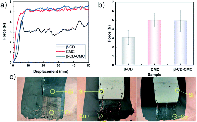
Fig. 4 shows the experimental results of the 180° peel experiment. The results show that the average peel force of the cross-linked binder is higher than that of β-CD. β-CD is a rigid molecule and inclined to form intramolecular hydrogen bonds. The intermolecular force within the β-CD is hydrogen bonds. This is suggested that the mechanical stability of β-CD is easily destroyed. The average peel strength is shown in Fig. 4(b). After being cross-linked with β-CD, the bonding properties of the CMC are slightly improved. Thanks to the introduction of β-CD, the multi-dimensional hydrogen bonding in the polymer is adapted to the volume changes of Si. A high-resolution optical camera shows that the stripped Si/β-CD exposes far more copper foil than the other samples suggest that one-dimensional, low-molecular β-CD is the leading cause of capacity decay.
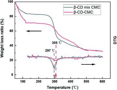
Thermogravimetric analysis (TG) confirms the presence of cross-linked structures as well (Fig. 5). The TG curves of the cross-linked β-CD-CMC samples are similar to those of the β-CD mixed with CMC in a 1![[thin space (1/6-em)]](https://www.rsc.org/images/entities/char_2009.gif) :
:![[thin space (1/6-em)]](https://www.rsc.org/images/entities/char_2009.gif) 1 mass ratio. There are two weight loss components of β-CD.38 Firstly, 50 °C to 110 °C corresponds to the loss of water molecules adsorbed externally and captured inside the cavity of β-CD. A rigid hydrogen bond exists in the unmodified β-CD molecule, when there is a hydrophobic surface and a hydrophilic surface of β-CD. The water molecules captured and adsorbed by β-CD are mainly contributed by the hydrophilic surface. After cross-linking with CMC, the rigid hydrogen bond of β-CD is broken, resulting in a variation of hydrophilicity of β-CD. To summarize, we consider that the difference in weight loss of the TG curves at 50–110 °C is caused by the varying amounts of water molecules adsorbed externally and captured in the cavity of β-CD. 250 °C to 400 °C corresponds to the thermal decomposition of β-CD and CMC. Cross-linking occurs mainly on the hydroxyl groups of β-CD and CMC. The β-CD and CMC without cross-linking contain a large amount of hydroxyl groups, and this part of hydroxyl groups will be lost after cross-linking. We suggest that the difference is caused by the different hydroxyl content. The formation of cross-linked β-CD-CMC keeps the original molecular structure of the raw material, on top of which covalent and hydrogen bonds of cross-linking are introduced, which is the major reason for the improved thermal stability, and the weight loss peak increases from 297 to 305 °C.
1 mass ratio. There are two weight loss components of β-CD.38 Firstly, 50 °C to 110 °C corresponds to the loss of water molecules adsorbed externally and captured inside the cavity of β-CD. A rigid hydrogen bond exists in the unmodified β-CD molecule, when there is a hydrophobic surface and a hydrophilic surface of β-CD. The water molecules captured and adsorbed by β-CD are mainly contributed by the hydrophilic surface. After cross-linking with CMC, the rigid hydrogen bond of β-CD is broken, resulting in a variation of hydrophilicity of β-CD. To summarize, we consider that the difference in weight loss of the TG curves at 50–110 °C is caused by the varying amounts of water molecules adsorbed externally and captured in the cavity of β-CD. 250 °C to 400 °C corresponds to the thermal decomposition of β-CD and CMC. Cross-linking occurs mainly on the hydroxyl groups of β-CD and CMC. The β-CD and CMC without cross-linking contain a large amount of hydroxyl groups, and this part of hydroxyl groups will be lost after cross-linking. We suggest that the difference is caused by the different hydroxyl content. The formation of cross-linked β-CD-CMC keeps the original molecular structure of the raw material, on top of which covalent and hydrogen bonds of cross-linking are introduced, which is the major reason for the improved thermal stability, and the weight loss peak increases from 297 to 305 °C.
3.2. Effect of cross-linking binder on Si based electrodes
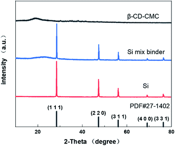
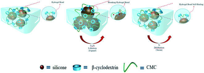
XRD technology tested the crystal structure of the binder mixed with Si and the results are shown in Fig. 6. Our commercial silicon has a crystalline silicon core coated with a silicon oxide layer. However, the oxide layer was too thin to be detected by XRD.39 However, the crystalline structure of the Si nanoparticles can be demonstrated from Fig. 6. The peaks of the individual features in the results are consistent with Si's PDF card (PDF#27-1402).The strategy for this paper is shown in Fig. 7. Three-dimensional polymers outperform linear and branched polymers. The cross-linked network of the binder is formed by covalent interactions. The network structure provides many intersection points. These intersections effectively disperse the large stresses generated during the cycle. The hydroxyl group on the Si surface can form hydrogen bonds with the hydroxyl group on the β-CD. Some covalent bonds similar to ester groups may be formed on drying, leading to stronger interactions between the Si nanoparticles and the binder network.22 Hydrogen bonding interactions can induce binder attachment to the surface of the Si particles prior to cycling for the purpose of controlling the SEI film.40 During the Si alloying process, hydrogen bonds are broken due to the compression of the volume changing Si particles. But the solid mechanical properties of the binder network can disperse and dissolve these stresses. Hydrogen bonding interactions are dynamic. During Si dealloying, the hydrogen bonding interaction forces are reconstructed. β-CD has a high hydroxyl content and can achieve strong interactions with Si nanoparticles. Therefore β-CD has the potential to be a promising binder.
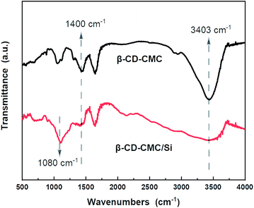
FTIR tests were performed on β-CD-CMC/Si to investigate the multi-dimensional interactions between Si and binder. As shown in Fig. 8, two absorption peaks appeared for Si nanopowder at 890 cm−1 and 1080 cm−1. This is due to the symmetric and asymmetric stretching vibrations of the Si–O–Si bond. When combined with β-CD-CMC, the –O–H peak has taken a significant shift and deformation, indicating that hydrogen bonding interactions between the binder and Si. Notably, the peak at 1400 cm−1 changes to a broad one, and the relative peak intensity decreases, reflects the formation of chemical interactions between β-CD-CMC and Si.22 The intense interaction between the binder and the active Si material during cycling facilitates the integrity of the electrode, mitigating the damage to the electrode structure due to significant volume changes of Si.
3.3. Electrochemical performance
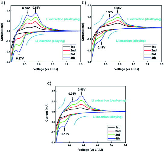
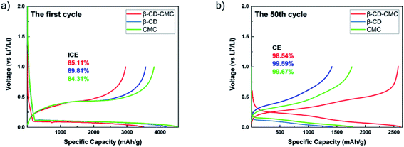
In order to characterize the electrochemical behaviour of the silicon-based electrodes, CV tests were carried out for the first four charge/discharge cycles. The test results are shown in Fig. 9. The three binders CMC, β-CD and β-CD-CMC have similar reaction voltages. There is a broad cathodic peak at 0.17–0.18 V, corresponding to the Li insertion (alloying). Two anodic peaks appear near 0.36 V and 0.53–0.56 V for charging process, corresponding to the Li extraction (dealloying). The intensity of the alloying and dealloying peaks of Si increases continuously in the CV test. This phenomenon can be attributed to the activation of Si nanoparticles.41,42 CV results are obtained at a constant voltage scan rate. It can therefore be assumed that some Si nanoparticles are not initially involved in the reaction. In subsequent cycles, unreacted Si nanoparticles were added to the reaction, increasing peak intensity. Eventually, the CV becomes stable.The capacity–voltage curves are shown in Fig. 10(a) and (b). During the first discharge, there is a clear voltage plateau between 0 and 0.18 V. This lithiation process is related to the peak at 0.17 V in the CV test. During the first charge, plateaus occur around 0.3 V–0.4 V and 0.55 V respectively. This de-lithiation process is associated with peaks at 0.36 V and 0.55 V in cyclic voltammetry tests.43 From Fig. 10(a), the first charge/discharge capacities of Si/β-CD-CMC, Si/β-CD and Si/CMC are 2962/3471 mA h g−1, 3565/4188 mA h g−1 and 3818/4529 mA h g−1 respectively. The corresponding coulombic efficiencies are 85.11%, 89.81% and 84.31% respectively. The cross-linked binder did not exhibit the highest coulomb efficiency and the highest reversible capacity on the first cycle. This phenomenon may be due to the large voids formed by the cross-linked binder network and the incomplete coverage of the Si surface, resulting in the uncontrolled growth of SEI. During subsequent cycles, however, the cross-linked binder can continuously adapt to the changing volume of the Si nanoparticles. The volume–voltage curve after 50 cycles is shown in Fig. 10(b). All electrodes undergo decay in capacity after cycling. Although Si/β-CD and Si/CMC have a high initial reversible capacity, they decrease significantly after 50 cycles. They are 1418 mA h g−1 and 1769 mA h g−1 respectively. In contrast, Si/β-CD-CMC still has a high discharge specific capacity of 2575 mA h g−1 after 50 cycles. The capacity retention rate reaches 86.9%, illustrated that Si/β-CD-CMC has better cycling properties.
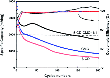
To further investigate the cycling performance of each electrode, charge and discharge tests were carried out on each electrode at a current density of 0.5C. The results of the test are shown in Fig. 11. Si/β-CD has the fastest rate of decline. Due to the poor adhesion of the β-CD, resulted in the exfoliation of electrode material from the collector. There is no strong bonding between each individual molecule in low molecular mass β-CD. The β-CD is not sufficient to withstand the huge expansion of Si nanoparticles during lithiation, which limits the cycling stability. Although the mechanical properties of CMC are close to those of β-CD-CMC(shown in Fig. 4), CMC still produces substantial capacity decay. This can be attributed to the random distribution of carboxyl groups in CMC.44 The inhomogeneous distribution of functional groups results in the CMC not being able to make multi-dimensional contact with the Si nanoparticles and provides excellent mechanical strength to resist the volume expansion of Si. Unlike CMC, β-CD has the advantage of a homogeneous distribution of functional groups. The hydroxyl groups in β-CD are evenly distributed in each monomeric unit. As a result, β-CD can be uniformly covered on the surface of the Si nanoparticles, forming a stable SEI layer on the surface of the Si particles. Furthermore, in contrast to CMC, which is rich in hydroxyl and carboxyl groups, cyclodextrins are only rich in hydroxyl groups. Thus β-CD interacts better with the oxidised surface of Si nanoparticles.45
From the Coulomb curve in Fig. 11, we can observe that the Coulomb efficiency curve of β-CD-CMC/Si electrode shows an increasing trend from low to high, and the same Coulomb curve trend can be expected in the study of Jeong et al. on xanthan gum as a silicon based anode binder.46 We argue that the key reason is the presence of pores in the network of the cross-linked binder, which results in a small number of particles not being completely coated by the binder. This part of particles generates an uncontrollable SEI layer in the pre-circulation period. At the late stage of cycling, these uncoated particles fall off and no more electrode reaction occurs, and at that time the Coulomb efficiency of the β-CD-CMC/Si electrode gradually grows and eventually exceeds that of the β-CD/Si and CMC/Si electrodes.
To combine the advantages of β-CD with CMC, β-CD is cross-linked to CMC using EPI. Cross-linked networks can significantly improve the cycling performance of electrodes. The cross-linked polymer network ensures that the binder adheres to the surface of the Si with multi-dimensional non-covalent interactions (shown in Fig. 12(a)). During the lithiation process, the Si particles stretch the polymer network outwards due to the enormous volume expansion of Si. Thanks to the β-CD anchor points on the cross-linked binder, the constructed polymer network can effectively withstand these stresses. As shown in the SEM diagram of Fig. 12(b). The enormous stresses are evenly dispersed everywhere, allowing the entire structure to be maintained. With 200 cycles at 0.5C current, it still maintains a capacity of 1702 mA h g−1, a capacity retention rate of 49%.
Aiming to understand the silicon-based electrodes' failure mechanism, the electrode surface morphology before and after cycling was observed. The surface morphology for each original electrode shown in Fig. 13(a)–(c) is uniformly coated on the copper foil. There are no significant differences in the morphology of each electrode before cycling.
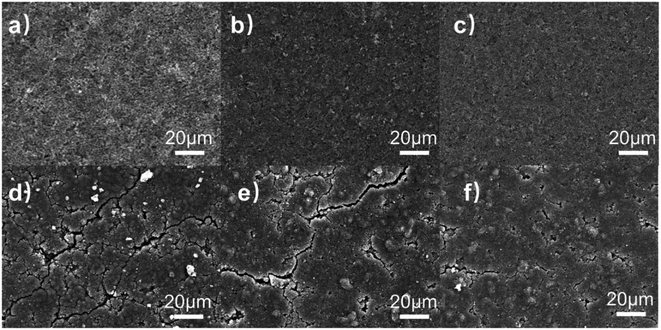 | ||
| Fig. 13 (a to c) The surface morphology of CMC/Si, β-CD/Si and β-CD-CMC/Si (d to f) The morphology of the electrodes after 50 cycles. | ||
The morphology of the electrodes after 50 cycles is shown in Fig. 13(d)–(f), respectively. Both the Si/CMC and Si/β-CD electrodes have developed more cracks and most of the surface is not smooth (Fig. 13(d) and (e)). However, Si/β-CD electrodes produce much finer and deeper cracks than Si/CMC. The formation of cracks in β-CD is that the low molecular weight β-CD cannot withstand the enormous stresses, as can also be seen in the tensile tests. The cracks in CMC arise from the sliding of linear molecules. Cross-linked Si/β-CD-CMC electrodes produce only a few and minor cracks after energy cycling. In terms of mechanical properties, this is due to the cross-linked binder maintaining the adhesion of the CMC. The cross-linked binder has a better mesh structure to accommodate the volume expansion of the Si nanoparticles. β-CD-CMC avoids the slippage of linear molecules and maintains electrode integrity, resulting in better electrochemical performance. It is also worth noting that some distinct protrusions can be observed in the SEM image of the Si/β-CD-CMC electrode after cycling which due to the significant volume change of Si squeezing the cross-linked network into deformation. The poor resilience of the CMC resulted in the network not being able to recover. This may also be an essential reason for the capacity degradation of Si/β-CD-CMC electrodes.
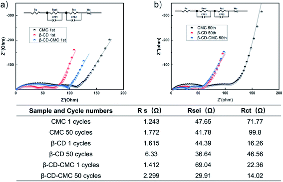
To further understand the formation of the SEI layer, EIS tests were carried out and the test results are shown in Fig. 14. All electrodes are tested in a fully discharged state. The test result graph consists of three resistors. They correspond to the ultra high-frequency region Rs, the high-frequency region Rsei and the medium frequency region Rct.35 All data were fitted using the same equivalent circuit and the fit results are given in table. The β-CD-CMC binder has the largest Rsei for the first cycle. This is due to the large voids formed by the cross-linked binder network, which fails to completely cover the surface of the Si in the first cycle, resulting in the uncontrolled growth of the SEI. This result is consistent with the one obtained from Fig. 10(a). The SEI of the β-CD-CMC electrode was controlled after subsequent cycles, leading to a reduction in Rsei. The same trend can be seen with the β-CD binder. The CMC binder and β-CD binder, while stabilizing the growth of the SEI layer, do not maintain the integrity of the electrode after multiple cycles, leading to an increase in Rct. The results show that the three-dimensional cross-linking strategy is very promising and effective.
4. Conclusion
The 3D network structure formed by the two different components of the cross-linked binder is beneficial for Si negative electrode materials. This three-dimensional structure can withstand the significant volume changes generated by Si during charging and discharging. The reactive groups (hydroxyl, carboxyl) in the binder form a stable chemical bond with Si. These chemical bonds help the electrode maintain structural stability over long cycles, resulting in a high reversible capacity. (1) The three-dimensional structure is important for regulating the volume deformation of silicon-based electrodes during cycling. β-CD-CMC has a three-dimensional structure while inheriting the adhesion ability of CMC, which can better obtain long cycling performance. (2) Because of the addition of β-CD, β-CD-CMC can also stabilize the SEI layer generated by silicon particles during charging and discharging to a certain extent. (3) The hydrogen bonding present inside β-CD-CMC can self-repair the cracks generated in the electrode during cycling to a certain extent. The Si/β-CD-CMC electrode maintains a reversible capacity of 1702 mA h g−1 even after 200 cycles at a high current of 0.5C. This electrode is significantly higher than the Si/β-CD and Si/CMC electrodes. Thus β-CD-CMC is an effective green binder for Si-based electrodes and offers a new option for future industrial development.Conflicts of interest
There are no conflicts to declare.Acknowledgements
The authors appreciate the financial support from the Guangxi Natural Science Foundation (No. 2021GXNSFAA220115) and the National Natural Science Foundation of China (No. 51864005).Notes and references
- N. Nitta, F. Wu, J. T. Lee and G. Yushin, Mater. Today, 2015, 18, 252–264 CrossRef CAS.
- G. Zhou, F. Li and H. Cheng, Energy Environ. Sci., 2014, 7, 137–1338 Search PubMed.
- Y. Hu and X. Sun, J. Mater. Chem. A, 2014, 2, 10712–10738 RSC.
- D. Shao, H. Zhong and L. Zhang, ChemElectroChem, 2014, 1, 1679–1687 CrossRef CAS.
- Y. Liu, G. Zhou, K. Liu and Y. Cui, Acc. Chem. Res., 2017, 50, 2895–2905 CrossRef CAS PubMed.
- M. T. McDowell, S. W. Lee, I. Ryu, H. Wu, W. D. Nix, J. W. Choi and Y. Cui, Nano Lett., 2011, 11, 4018–4025 CrossRef CAS PubMed.
- H. Zhao, W. Yuan and G. Liu, Nano Today, 2015, 10, 193–212 CrossRef CAS.
- N. Liu, Z. Lu, J. Zhao, M. T. McDowell, H. Lee, W. Zhao and Y. Cui, Nat. Nanotechnol., 2014, 9, 187–192 CrossRef CAS PubMed.
- R. Tang, L. Ma, Y. Zhang, X. Zheng, Y. Shi, X. Zeng, X. Wang and L. Wei, ChemElectroChem, 2020, 7, 1992–2000 CrossRef CAS.
- H. Chen, M. Ling, L. Hencz, H. Y. Ling, G. Li, Z. Lin, G. Liu and S. Zhang, Chem. Rev., 2018, 118, 8936–8982 CrossRef CAS PubMed.
- A. N. Preman, H. Lee, J. Yoo, I. T. Kim, T. Saito and S. Ahn, J. Mater. Chem. A, 2020, 8, 25548–25570 RSC.
- M. Zheng, X. Fu, Y. Wang, J. Reeve, L. Scudiero and W. Zhong, ChemElectroChem, 2018, 5, 2288–2294 CrossRef CAS.
- Y. Shi, X. Zhou and G. Yu, Acc. Chem. Res., 2017, 50, 2642–2652 CrossRef CAS PubMed.
- D. Bresser, D. Buchholz, A. Moretti, A. Varzi and S. Passerini, Energy Environ. Sci., 2018, 11, 396–3127 RSC.
- U. S. Vogl, P. K. Das, A. Z. Weber, M. Winter, R. Kostecki and S. F. Lux, Langmuir, 2014, 30, 10299–10307 CrossRef CAS PubMed.
- J. Liu, Q. Zhang, T. Zhang, J. Li, L. Huang and S. Sun, Adv. Funct. Mater., 2015, 25, 3599–3605 CrossRef CAS.
- Y. Bie, J. Yang, Y. Nuli and J. Wang, J. Mater. Chem. A, 2017, 5, 1919–1924 RSC.
- L. Yue, L. Zhang and H. Zhong, J. Power Sources, 2014, 247, 327–331 CrossRef CAS.
- S. Komaba, K. Shimomura, N. Yabuuchi, T. Ozeki, H. Yui and K. Konno, J. Phys. Chem. C, 2011, 115, 13487–13495 CrossRef CAS.
- B. Koo, H. Kim, Y. Cho, K. T. Lee, N. Choi and J. Cho, Angew. Chem., Int. Ed., 2012, 51, 8762–8767 CrossRef CAS PubMed.
- Y. Liu, Z. Tai, T. Zhou, V. Sencadas, J. Zhang, L. Zhang, K. Konstantinov, Z. Guo and H. K. Liu, Adv. Mater., 2017, 29, 1703028 CrossRef PubMed.
- S. Chen, H. Y. Ling, H. Chen, S. Zhang, A. Du and C. Yan, J. Power Sources, 2020, 450, 227671 CrossRef CAS.
- J. Wang, C. Wan and J. Hong, ChemElectroChem, 2020, 7, 3106–3115 CrossRef CAS.
- F. M. Bezerra, M. J. Lis, H. B. Firmino, J. G. Dias Da Silva, R. D. C. S. Curto Valle, J. A. Borges Valle, F. A. P. Scacchetti and A. L. Tessaro, Molecules, 2020, 25, 3624 CrossRef CAS PubMed.
- K. Kiti and O. Suwantong, Int. J. Biol. Macromol., 2020, 164, 3250–3258 CrossRef CAS PubMed.
- Y. K. Jeong, T. Kwon, I. Lee, T. Kim, A. Coskun and J. W. Choi, Nano Lett., 2014, 14, 864–870 CrossRef CAS PubMed.
- T. Kwon, Y. K. Jeong, E. Deniz, S. Y. AlQaradawi, J. W. Choi and A. Coskun, ACS Nano, 2015, 9, 11317–11324 CrossRef CAS PubMed.
- F. Zeng, W. Wang, A. Wang, K. Yuan, Z. Jin and Y. Yang, ACS Appl. Mater. Inter, 2015, 7, 26257–26265 CrossRef CAS PubMed.
- J. Drofenik, M. Gaberscek, R. Dominko, F. W. Poulsen, M. Mogensen, S. Pejovnik and J. Jamnik, Electrochim. Acta, 2003, 48, 883–889 CrossRef CAS.
- J. Li, R. B. Lewis and J. R. Dahn, Electrochem. Solid-State Lett., 2007, 10, A17 CrossRef CAS.
- F. Wu, W. Li, L. Chen, Y. Lu, Y. Su, W. Bao, J. Wang, S. Chen and L. Bao, J. Power Sources, 2017, 359, 226–233 CrossRef CAS.
- N. S. Hochgatterer, M. R. Schweiger, S. Koller, P. R. Raimann, T. Wöhrle, C. Wurm and M. Winter, Electrochem. Solid-State Lett., 2008, 11, A76 CrossRef CAS.
- J. S. Bridel, T. Azaïs, M. Morcrette, J. M. Tarascon and D. Larcher, Chem. Mater., 2010, 22, 1229–1241 CrossRef CAS.
- D. Jeong, S. Joo, Y. Hu, V. V. Shinde, E. Cho and S. Jung, Eur. Polym. J., 2018, 105, 17–25 CrossRef CAS.
- H. Mi, X. Yang, F. Li, X. Zhuang, C. Chen, Y. Li and P. Zhang, J. Power Sources, 2019, 412, 749–758 CrossRef CAS.
- J. Zhang, N. Wang, W. Zhang, S. Fang, Z. Yu, B. Shi and J. Yang, J. Colloid Interface Sci., 2020, 578, 452–460 CrossRef CAS PubMed.
- S. Lv, R. Gao, Q. Cao, D. Li and J. Duan, Cem. Concr. Res., 2012, 42, 1356–1361 CrossRef CAS.
- Y. Zhou, R. Zhang, K. Chen, X. Zhao, X. Gu and J. Lu, J. Taiwan Inst. Chem. Eng., 2017, 78, 510–516 CrossRef CAS.
- D. Munao, J. W. M. van Erven, M. Valvo, E. Garcia-Tamayo and E. M. Kelder, J. Power Sources, 2011, 196, 6695–6702 CrossRef CAS.
- D. Bo, H. Xuanning, C. Zhenfei, M. Yangzhou, S. Guangsheng, Y. Weidong and W. Cuie, Inorg. Chem. Commun., 2020, 113, 107771 CrossRef CAS.
- C. Chen, S. H. Lee, M. Cho, J. Kim and Y. Lee, ACS Appl. Mater. Inter, 2016, 8, 2658–2665 CrossRef CAS PubMed.
- H. Zhong, J. He and L. Zhang, Polymer, 2021, 215, 123377 CrossRef CAS.
- Y. Wang, H. Xu, X. Chen, H. Jin and J. Wang, Energy Storage Materials, 2021, 38, 121–129 CrossRef.
- D. Mazouzi, B. Lestriez, L. Roué and D. Guyomard, Electrochem. Solid-State Lett., 2009, 12, A215 CrossRef CAS.
- J. Ryu, S. Kim, J. Kim, S. Park, S. Lee, S. Yoo, J. Kim, N. S. Choi, J. H. Ryu and S. Park, Adv. Funct. Mater., 2019, 30, 1908433 CrossRef.
- Y. K. Jeong, T. Kwon, I. Lee, T. Kim, A. Coskun and J. W. Choi, Energy Environ. Sci., 2015, 8, 1224–1230 RSC.
Footnote |
| † Electronic supplementary information (ESI) available. See DOI: 10.1039/d1ra08538g |
| This journal is © The Royal Society of Chemistry 2022 |

