 Open Access Article
An in situ DRIFTS study on nitrogen electrochemical reduction over an Fe/BaZr0.8Y0.2O3−δ-Ru catalyst at 220 °C in an electrolysis cell using a CsH2PO4/SiP2O7 electrolyte
Yao Yuana,
Naoya Fujiwaraa,
Shohei Tada b and
Ryuji Kikuchi
 *a
*a
aDepartment of Chemical System Engineering, The University of Tokyo, 7-3-1, Hongo, Bunkyo-ku, Tokyo 113-8656, Japan. E-mail: rkikuchi@chemsys.t.u-tokyo.ac.jp
bDepartment of Materials Sciences and Engineering, Ibaraki University, Ibaraki, 316-8511, Japan
First published on 17th March 2022
Abstract
In situ DRIFTS measurements of an Fe/BZY-Ru cathode catalyst in an electrolysis cell using a CsH2PO4/SiP2O7 electrolyte were carried out in a mixed N2–H2 gas flow under polarization. The formation of N2Hx species was confirmed under polarization, and an associative mechanism in the electrochemical NRR process was verified.
NH3 production contributes about 2% of the world's energy consumption annually, and most of the consumption is from the strongly endothermic steam reforming of methane (SRM) at 800–1000 °C in the Haber–Bosch process. Other major energy consuming processes include CO2 removal, reactant gas purification, reactant gas compression for NH3 synthesis, and NH3 separation.1 Due to its high energy density, NH3 was expected to be a promising energy carrier in recent years.2 NH3 produced by renewable energy sources can be used as a carbon-free energy carrier. One of the promising methods to utilize renewable energy sources for NH3 production is electrochemical N2 reduction. Various electrolysis cells with solid and liquid electrolytes have been reported for electrochemical N2 reduction over a wide temperature range. For the electrochemical N2 reduction reaction (NRR) at low temperatures (T < 100 °C), the main limitation is the difficulty of N2 activation and the low solubility of N2 in aqueous media. High temperatures (T > 500 °C) can lead to decomposition of the produced NH3. Hence, an electrochemical NRR at intermediate temperatures is desirable. Phosphates such as CsH2PO4 and CsH5(PO4)2 are typically used as electrolytes at intermediate temperatures. These inorganic oxyacid salts have high proton conductivity and stability. CsH2PO4 mixed with SiP2O7 as a matrix exhibits a proton conductivity of ca. 1 × 10⁻² S cm−1 at 220 °C.3 In our previous work on electrochemical NH3 synthesis using an Fe/BZY-RuO2 catalyst and CsH2PO4/SiP2O7 electrolyte at 220 °C and ambient pressure, the highest current efficiency of 7.1% and the highest NH3 yield rate of 4.5 × 10⁻¹⁰ mol (s−1 cm2) were achieved at −0.4 V (vs. open circuit voltage (OCV)) and −1.5 V, respectively. In addition, N2H4 was successfully detected at −0.2 V (vs. OCV), which indicated an associative mechanism,4 which is one of the two main reaction mechanisms in NH3 synthesis, namely, associative and dissociative mechanisms. In the associative mechanism the N
![[triple bond, length as m-dash]](https://www.rsc.org/images/entities/char_e002.gif) N bond in a N2 molecule adsorbed on the catalyst surface is cleaved after an H atom attaches to the N atom of the adsorbed N2 molecule, whereas in the dissociative mechanism the N
N bond in a N2 molecule adsorbed on the catalyst surface is cleaved after an H atom attaches to the N atom of the adsorbed N2 molecule, whereas in the dissociative mechanism the N![[triple bond, length as m-dash]](https://www.rsc.org/images/entities/char_e002.gif) N bond is broken on the catalyst surface before an H atom attaches to the N2 molecule.
N bond is broken on the catalyst surface before an H atom attaches to the N2 molecule.
Typical electrochemical characterizations such as impedance spectroscopy,5,6 current–voltage curve (IV curve) testing,7,8 cyclic voltammetry,9 and potentiostatic pulse experiment10 can only provide indirect information on surface reactions at the electrode. It is indispensable to analyse directly adsorbed species on the electrode catalysts for the understanding of the reaction mechanism. In situ spectroscopy is making rapid progress and has already been applied to electrochemical devices, providing valuable information of the chemical species during the reactions.11 In situ diffuse reflectance infrared Fourier transform spectroscopy (DRIFTS) for electrolysis cells attracts much attention recently.12,13 In situ DRIFTS has recently become a powerful tool for investigating the reaction pathway in electrochemical N2 reduction reaction.14–16 In DRIFTS, infrared (IR) beam irradiates the sample disk, and then can be reflected at or transmitted through the sample disk. The scattered IR beam is collected by the spherical focusing mirrors and finally converted by a detector.
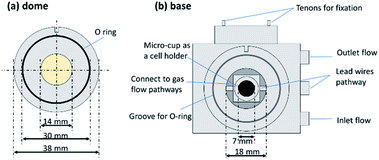
In this work, a commercial DRIFTS setup was modified and applied to electrochemical N2 reduction as shown in Fig. 1. To enable an operation temperature higher than 200 °C that is requisite for proton conduction in the electrolyte, an electrical heating wire was placed in the base near the micro-cup. The temperature was measured by a thermocouple located next to the heating wire. An electrolysis cell was set on the micro-cup of the metal base. For protection of the ZnSe window from oxidation at the high operating temperature, a water-cooling system was attached to the metal base near the dome to keep the temperature of the window below 200 °C. The specific size of the apparatus is shown in the Fig. 2. An O-ring fits to the dome can ensure gas tightness of the small space in the dome. There are three pathways which connect the inside space of the dome and atmosphere. Two of them are used for the inlet and outlet gas flows, and the one connecting directly with the micro-cup was used for Pt lead wires. To avoid a short-circuit between the two Pt lead wires, a thin polyimide film (12.5 μm thick, Kapton, Dupont, Delaware, United States) which is stable from −269 to +400 °C was used to cover the Pt wires.
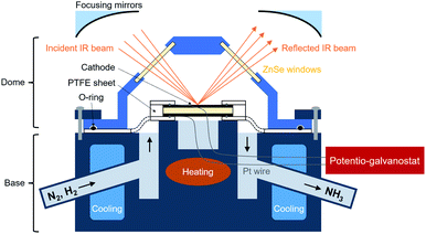 | ||
| Fig. 1 A schematic of modified DRIFTS setup applied to electrochemical N2 reduction. The temperature of the electrolysis cell is measured at the same place where it is heated. | ||
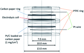
In our previous study of the electrochemical NH3 synthesis process at 220 °C, a ø 10 mm carbon paper was used on the cathode side to increase the current collection area.4 However, in the in situ DRIFTS tests, the cathode catalysts must be exposed to the IR beam, hence a carbon ring with an inside diameter of 7 mm was used instead as shown in Fig. 3. On the anode side, a ø 10 mm Pt/C loaded on carbon paper was used for current collection. The electrolysis cell consists of 0.1 g SiP2O7/CsH2PO4 electrolyte (mix ratio of SiP2O7![[thin space (1/6-em)]](https://www.rsc.org/images/entities/char_2009.gif) :
:![[thin space (1/6-em)]](https://www.rsc.org/images/entities/char_2009.gif) CsH2PO4 was 1
CsH2PO4 was 1![[thin space (1/6-em)]](https://www.rsc.org/images/entities/char_2009.gif) :
:![[thin space (1/6-em)]](https://www.rsc.org/images/entities/char_2009.gif) 1) compressed with 0.035 g Fe/BZY-Ru (mix ratio of Fe/BZY
1) compressed with 0.035 g Fe/BZY-Ru (mix ratio of Fe/BZY![[thin space (1/6-em)]](https://www.rsc.org/images/entities/char_2009.gif) :
:![[thin space (1/6-em)]](https://www.rsc.org/images/entities/char_2009.gif) RuO2 was 1
RuO2 was 1![[thin space (1/6-em)]](https://www.rsc.org/images/entities/char_2009.gif) :
:![[thin space (1/6-em)]](https://www.rsc.org/images/entities/char_2009.gif) 1) catalyst on the top layer. In our previous work of the electrochemical NH3 synthesis using Fe/BZY-RuO2, we have successfully detected N2H4 as well as NH3, which indicated the triple bond of N2 was broken simultaneously with the addition of H. Fe/BZY was prepared in the same way as in the previous work.4 The as-prepared Fe/BZY powder was mixed with RuO2 powder, and then the mixture was reduced in H2 flow at 220 °C for 1 h. To fix the electrolysis cell, the current collection materials and the Pt lead wires, PTFE sheets (Gore Hyper-Sheet Gasket, W. L. Gore & Associate, Inc., Delaware, USA) formed into rings were used as the support. The experimental conditions in the dome are similar to those in a single-chamber reactor. The inlet gas is a mixture of N2 and H2, which is different from the two-chamber reactor in electrolysis tests in the previous work. A background spectrum was measured under H2 gas flow of 8 mL min−1 at 160 °C with 100 scans at OCV. All DRIFTS spectra are displayed as log(I0/I) where I0/I is the relative reflectance (I0 is the background reflectance). Then the measurements were carried out under N2 gas flow of 8 mL min−1 at 300 °C at OCV and under mixed N2 and H2 gas flow (both are 8 mL min−1) at 250 °C at OCV and various applied biases.
1) catalyst on the top layer. In our previous work of the electrochemical NH3 synthesis using Fe/BZY-RuO2, we have successfully detected N2H4 as well as NH3, which indicated the triple bond of N2 was broken simultaneously with the addition of H. Fe/BZY was prepared in the same way as in the previous work.4 The as-prepared Fe/BZY powder was mixed with RuO2 powder, and then the mixture was reduced in H2 flow at 220 °C for 1 h. To fix the electrolysis cell, the current collection materials and the Pt lead wires, PTFE sheets (Gore Hyper-Sheet Gasket, W. L. Gore & Associate, Inc., Delaware, USA) formed into rings were used as the support. The experimental conditions in the dome are similar to those in a single-chamber reactor. The inlet gas is a mixture of N2 and H2, which is different from the two-chamber reactor in electrolysis tests in the previous work. A background spectrum was measured under H2 gas flow of 8 mL min−1 at 160 °C with 100 scans at OCV. All DRIFTS spectra are displayed as log(I0/I) where I0/I is the relative reflectance (I0 is the background reflectance). Then the measurements were carried out under N2 gas flow of 8 mL min−1 at 300 °C at OCV and under mixed N2 and H2 gas flow (both are 8 mL min−1) at 250 °C at OCV and various applied biases.
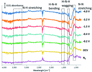
According to the results in Fig. 4, three kinds of sharp peaks at 1050, 1300 and 1540 cm−1, and a broad peak at 3300 cm−1 were observed. Peak at 1050 cm−1 is attributed to N–N stretching (reported at 1106 cm−1),17 which appeared in all experimental conditions even when only N2 gas was supplied. This implies that the N2 adsorption sites on the catalyst surface are highly active. Peaks at 1300, 1540 and 3300 cm−1 are assigned to H–N–H wagging, H–N–H bending and N–H stretching (reported at 1270, 1461 and 3235 cm−1).17 These three kinds of peaks appeared only when both N2 and H2 were supplied, and seem to become stronger with applied bias. It is obvious that N2Hx species, which can be intermediate species in the associative mechanism, were formed on the surface of Fe/BZY-Ru. The peak at 900 cm−1 is probably attributed to NH3 gas.18 It is likely that the peaks at 1400 cm−1 and 2800 cm−1 are assigned to NH4+.19 The strong signal at 2360 cm−1 is associative with gas-phase CO2 that exists in IR beam path outside the dome.
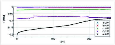
Only quite low current densities were able to be loaded as shown in Fig. 5. Reactant gases were introduced to the system without humidification, which might have led to low proton conductivity and electrolyte decomposition. In addition, current collection area of the carbon paper ring on the cathode side is small.
In situ DRIFTS measurements were carried out in a N2–H2 gas mixture under polarization, which corresponds to a situation in a single-chamber reactor. The background was measured in H2 flow, and the sample measurements were carried out in a mixed N2–H2 gas flow. In the obtained spectra, a peak at 1100 cm−1 was assigned to N–N stretching, and those at 1301, 1600, and 3300 cm−1 were assigned to –NH2 wagging, H–N–H bending, and N–H stretching. The intensity of the H–N–H wagging peak was enhanced by increasing the applied voltage. Appearance of these peaks confirmed the formation of N2Hx (1 ≤ x ≤ 4) species in the NRR process and consequently demonstrated that NRR proceeded via an associative mechanism over Fe/BZY-Ru cathode catalyst on a SiP2O7/CsH2PO4 electrolyte.
Author contributions
Yao Yuan: investigation, data curation, formal analysis, writing – original draft. Naoya Fujiwara: methodology, resources, visualization. Shohei Tada: methodology, data curation, formal analysis. Ryuji Kikuchi: conceptualization, supervision, writing – review & editing.Conflicts of interest
There are no conflicts to declare.Acknowledgements
A part of this work was supported by Japan Society for the Promotion of Science (JSPS) KAKENHI Grant Number JP20J14232, Japan, and Japan Science and Technology Agency (JST) Core Research for Evolutional Science and Technology (CREST) Grant Number JPMJCR1441, Japan.References
- I. Rafiqul, C. Weber, B. Lehmann and A. Voss, Energy, 2005, 30, 2487–2504 CrossRef CAS.
- N. V. Rees and R. G. Compton, Energy Environ. Sci., 2011, 4, 1255–1260 RSC.
- N. Fujiwara, H. Nagase, S. Tada and R. Kikuchi, ChemSusChem, 2021, 14, 417–427 CrossRef CAS PubMed.
- Y. Yuan, S. Tada and R. Kikuchi, Mater. Adv., 2021, 2, 793–803 RSC.
- R. Lan and S. Tao, RSC Adv., 2013, 3, 18016–18021 RSC.
- B. Xu, L. Xia, F. Zhou, R. Zhao, H. Chen, T. Wang, Q. Zhou, Q. Liu, G. Cui, X. Xiong, F. Gong and X. Sun, ACS Sustainable Chem. Eng., 2019, 7, 2889–2893 CrossRef CAS.
- P. Shen, Y. Liu, Q. Li and K. Chu, Chem. Commun., 2020, 56, 10505–10508 RSC.
- Q. Fan, C. Choi, C. Yan, Y. Liu, J. Qiu, S. Hong, Y. Jung and Z. Sun, Chem. Commun., 2019, 55, 4246–4249 RSC.
- K. Fricke, F. Harnisch and U. Schröder, Energy Environ. Sci., 2008, 1, 144–147 RSC.
- Y. Jännsch, J. J. Leung, M. Hämmerle, E. Magori, K. Wiesner-Fleischer, E. Simon, M. Fleischer and R. Moos, Electrochem. Commun., 2020, 121, 106861 CrossRef.
- M. F. Baruch, J. E. Pander, J. L. White and A. B. Bocarsly, ACS Catal., 2015, 5, 3148–3156 CrossRef CAS.
- D. J. Cumming, C. Tumilson, S. F. R. Taylor, S. Chansai, A. V. Call, J. Jacquemin, C. Hardacre and R. H. Elder, Faraday Discuss., 2015, 182, 97–111 RSC.
- N. Shi, Y. Xie, D. Huan, Y. Yang, S. Xue, Z. Qi, Y. Pan, R. Peng, C. Xia and Y. Lu, J. Mater. Chem. A, 2019, 7, 4855–4864 RSC.
- Y. Yao, S. Zhu, H. Wang, H. Li and M. Shao, J. Am. Chem. Soc., 2018, 140, 1496–1501 CrossRef CAS PubMed.
- X. Qu, L. Shen, Y. Mao, J. Lin, Y. Li, G. Li, Y. Zhang, Y. Jiang and S. Sun, ACS Appl. Mater. Interfaces, 2019, 11, 31869–31877 CrossRef CAS PubMed.
- J.-T. Ren, C.-Y. Wan, T.-Y. Pei, X.-W. Lv and Z.-Y. Yuan, Appl. Catal., B, 2020, 266, 118633 CrossRef CAS.
- P. Song, H. Wang, L. Kang, B. Ran, H. Song and R. Wang, Chem. Commun., 2019, 55, 687–690 RSC.
- S. Süzer and L. Andrews, J. Chem. Phys., 1987, 87, 5131–5140 CrossRef.
- C. Sun and D. Xue, CrystEngComm, 2015, 17, 2728–2736 RSC.
| This journal is © The Royal Society of Chemistry 2022 |

