 Open Access Article
Polyhedral oligosilsesquioxane-modified boron nitride enhances the mechanical properties of polyimide nanocomposites†
Yajun Zhanga,
Jie Wanga and
Yinjie Chen *b
*b
aCollege of Mechanical and Electrical Engineering, Beijing University of Chemical Technology, Beijing 100020, China. E-mail: zhyj@mail.buct.edu.cn
bBeijing Engineering Research Center of Printed Electronics, Beijing Institute of Graphic Communication, Beijing 102600, China. E-mail: chenyinjie@bigc.edu.cn
First published on 2nd March 2022
Abstract
A novel high-strength polyimide (PI) nanocomposite film was designed and constructed by the copolymerization of epoxidized polyhedral oligomeric silsesquioxane-modified hexagonal boron nitride and polyamic acid (PAA). The composite filler (EPPOSS@Gh-BN) was composed of silane coupling agent KH550 modified hexagonal boron nitride (Gh-BN) and epoxidized polyhedral oligomeric silsesquioxanes (EPPOSS), which improved not only the dispersion of the h-BN but also the effective interfacial stress transfer, leading to an enhanced mechanical strength of the resultant PI nanocomposite film of 114 MPa even with a slight EPPOSS@Gh-BN loading of 0.30 wt%, and the storage modulus was increased by more than 30% to 4 GPa compared to pure PI. Meanwhile, the PI/EPPOSS@Gh-BN nanocomposite has better heat transfer performance, higher hydrophobicity, lower dielectric properties, and higher heat stability than pure PI, and is therefore expected to provide an ideal platform for the development of highly flexible electronics in the future.
1. Introduction
Polyimide (PI) has high chemical stability, temperature resistance, low dielectric properties, and electrical insulation properties, has been widely used as an insulating material in the electronics industry, machinery, medicine and other fields.1–7 However, PI has a slow heat transfer rate and larger electronic polarizability and therefore reduces the life of circuit components in wet environments and increases the dielectric constant in modern electronic devices.To address this issue, it is generally effective to introduce functional fillers into the polymer matrix.8,9 Common functional fillers include graphene,10–13 carbon nanotubes,14–16 boron nitride,17,18 and metal materials.19
However, graphene, carbon nanotubes, and metallic materials have high conductivity, dielectric constants and dielectric losses,16,20,21 which are not suitable for electronic insulation materials and seriously hinder the transmission of electronic signals in electronic packaging materials. Hexagonal boron nitride (h-BN) is a ceramic material with a structure similar to that of a graphene hexagon.22–25 h-BN is not only an excellent conductor of heat,26,27 but also an electrical insulator with a wide band gap,28,29 and its thermal conductivity is among the highest of all electric insulators; it is therefore ideal for improving the comprehensive performance of PI composite films.30,31 Currently, many studies describe h-BN composite fillers using carbon based nanomaterials such as graphene nanoplatelets, carbon nanotube and MWCNTs in the field of PI matrix, improving thermal conductivity while minimizing dielectric properties.8,11,15 However, the poor dispersion and weak interfacial interactions between h-BN and polymer matrix limit the reinforcement effects of h-BN.32–34
A common solution to the abovementioned issue involves the surface modification of h-BN, which enhances the dispersibility and compatibility of the polymer matrix. Silane coupling agents have been shown to improve the dispersity performance of graft-polymerization-modified h-BN fillers effectively.35–37 However, the mechanical properties of the BN/polymer composites did not increase significantly, thus they do not offer the flexibility required for application in flexible electronics, such as flexible printed circuits, soft robotics, wearable electronic sensors, flexible electronic displays, and other emerging application.38
Polyhedral oligomeric silsesquioxane (POSS) is an organic–inorganic hybrid nanomaterial that has been widely studied as an effective filler for low dielectric polymer composites owing to its unique hollow structure.39,40 In particular, the inorganic cubic-cage core provides mechanical properties.41 Guo et al.42 used KH560 to modify h-BN, and then combined the amino group on the NH2-POSS molecule with the epoxy group on KH560 to obtain POSS-modified h-BN (f-BN) successfully. When the f-BN content was 30 wt%, the thermal conductivity of the f-BN/PI composite increased to 0.71 W m K−1, which is higher than that of the BN/PI composites with 30 wt% BN (thermal conductivity of 0.69 W m K−1). However, few studies have been conducted to investigate the mechanical properties of POSS/PI composites.
In this study, the silane coupling agent KH550 was firstly used to pretreat h-BN (Gh-BN was obtained). Epoxy-based POSS (EPPOSS) was used as a modifier to achieve the synergy effect of the synthesis of EPPOSS@Gh-BN and ultrasonic liquid exfoliation of h-BN to obtain EPPOSS@Gh-BN nanosheets, in which the EPPOSS was prepared using the vinyl POSS (VIPOSS) cyclooxidation reaction. The PI/EPPOSS@Gh-BN nanocomposite films were prepared from a polyamic acid (PAA) (PI precursor) and EPPOSS@Gh-BN filler. It has a high tensile strength of 114 MPa and storage modulus of 4 GPa, better heat transfer performance, low dielectric constant of 3.27 and dielectric loss of 0.02, and thermal conductivity of 0.36 W m K−1, with 0.3 wt% content of EPPOSS@Gh-BN (0.2 wt% Gh-BN with 0.1 wt% EPPOSS). The preparation process of the PI/EPPOSS@Gh-BN nanocomposites is depicted in Scheme 1.
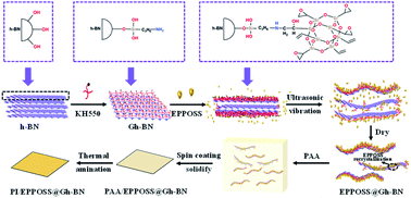 | ||
| Scheme 1 Schematic diagram of synthesis of composite filler EPPOSS@Gh-BN and PI/EPPOSS@Gh-BN nanocomposite film. | ||
2. Experimental section
2.1. Materials
Polyamic acid (PAA) was purchased from Dongguan Yipin Chemical Co., Ltd. Hexagonal boron nitride (h-BN, 0.1–1 μm) was obtained from Qinghe Chuangying Metal Material Co., Ltd. Silane coupling agent (KH550) was purchased from Nanjing Chenggong Silicone Material Co., Ltd. POSS-octavinyl substituted (VIPOSS) was supplied by Shanghai Aladdin Biochemical Technology Co., Ltd. 3-Chlorperoxybenzoic acid (MCPBA) was provided by Shanghai Macklin Biochemical Co., Ltd. Tetrahydrofuran (THF) and dichloromethane (DCM) were purchased from Tianjin Damao Chemical Reagent Factory. N,N-Dimethylacetamide (DMAc) and sodium sulfate were obtained from Sinopharm Chemical Reagent Co., Ltd. Sodium hydrogen carbonate was purchased from Tianjin Guangfu Technology Development Co., Ltd.2.2. Surface functionalization of h-BN fillers
Certain amounts of KH550 solution and h-BN were mixed and stirred for 4 h at 80 °C, followed by filtration and washing with ethanol and drying at 80 °C for another 24 h. Finally, KH550 was grafted onto h-BN (Gh-BN). Subsequently, EPPOSS was obtained by mixing 3.2 g of VIPOSS and 5.5 g of MCPBA in 40 mL of dichloromethane for a reflux reaction at 40 °C for 36 h. The solid m-chlorobenzoic acid in the middle of the suspension was filtered, the excess 3-chlorperoxybenzoic acid in dichloromethane was reduced with saturated sodium sulfite solution, and the newly generated m-chlorobenzoic acid was washed off with saturated sodium bicarbonate aqueous solution. Finally, the dichloromethane solution obtained by separation was rotary-evaporated to obtain the EPPOSS solids. The quantitative Gh-BN was poured into the EPPOSS/THF solution and stirred for 4 h at 60 °C, then filtered and dried to obtain EPPOSS-grafted Gh-BN (EPPOSS@Gh-BN).2.3. Fabrication of PI/EPPOSS@Gh-BN nanocomposite films
The composite films used silicon wafer as the substrate. The clean silicon wafer was first soaked into 30% hydrogen peroxide solution for 12 h. It was then cleaned with deionized water and vacuum dried at 80 °C for 2 h. Subsequently, it was treated with oxygen plasma for 5 min. The appropriate amounts of PAA, EPPOSS@Gh-BN and DMAc were mixed in a flask, and stirred for 30 min. The mixture was then allowed to stand for 1 h, at which time its viscosity was 6100 mPa s; it was finally spin-coated (60 rps, 2 s) onto the silicon wafer, followed by thermal imidization process (80 °C for 4 h, 120 °C for 1 h, 150 °C for 30 min, 200 °C for 10 min, 250 °C for 10 min). In this manner, the PI/EPPOSS@Gh-BN nanocomposite films of 80 μm were fabricated.2.4. Characterization
Fourier-transform infrared (FTIR) spectroscopy was performed on a TENSOR II (Bruker) spectrometer in the wavenumber range of 400–4000 cm−1. The silicon content on the hexagonal boron nitride surface was analysed by X-ray photoelectron spectroscopy (XPS) using an ESCALAB 250Xi electron spectrometer from Thermo Scientific. X-ray diffraction (XRD) analysis of hexagonal boron nitride was performed on a Rigaku (Japan) X-ray diffractometer MiniFlex 300/600. The fractured surface of epoxy composite films were observed using a JSM-7610FPlus thermal field emission scanning electron microscope (SEM). The composite sheets were firstly quenched with liquid nitrogen, and then the fracture surface was sputtered with thin layers of gold to avoid charge accumulation. The thermal conductivity coefficients of the composites were measured by a TPS 2500S (Hot Disk Crop., Sweden). Thermal gravimetry (TG) analysis was conducted by a TGA/DSC3+ (Mettler Toledo Crop., China), under nitrogen gas at a heating rate of 10 °C min−1. Thermomechanical analysis (TMA) was recorded on a TA-Q 400 thermal analysis system in nitrogen at a heating rate of 5 °C min−1. Dynamic mechanical analysis (DMA) was recorded on a TA-Q800 thermal analysis system at a heating rate of 3 °C min−1 and a frequency of 1 Hz in nitrogen. The tensile strength and strain properties of the composite films were tested using a tensile testing machine from Guangdong Dongfang Saniron Automation Technology. The contact angle images taken by an industrial camera were fitted using ImageJ software to measure the contact angle and determine the hydrophobic properties of the composite film accurately. The FLUKE TiS20 thermal imaging camera was used to take LED thermal imaging pictures of different substrates, and the Fluke Connect software measured the temperature range.3. Results and discussion
3.1. Structural analysis
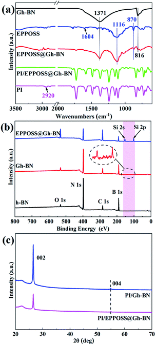
Characterization of the chemical structures of EPPOSS@Gh-BN and PI/EPPOSS@Gh-BN was performed as shown in Fig. 1(a) by FTIR. The spectrum of Gh-BN is similar to that of h-BN, exhibiting two obvious characteristic peaks at 1371 cm−1 and 816 cm−1, which correspond to in-plane B–N stretching vibrations and out-of-plane B–N–B bending vibrations, respectively.17,35 The bands observed at 2919 cm−1, 2850 cm−1 and 1100–900 cm−1 can be ascribed to (–CH4) antisymmetric and symmetric stretching and Si–O vibration absorption of h-BN covalently modified by KH550 as shown in Fig. S1(a).† The characteristic absorption peak of EPPOSS@Gh-BN is detected at 1116 cm−1, which is evidence of the presence of Si–O–Si vibration,40 confirming that EPPOSS was successfully grafted onto the surface of Gh-BN. The formation of EPPOSS by VIPOSS epoxidation reaction was confirmed by the absorption peaks at 1604 cm−1 (–C![[double bond, length as m-dash]](https://www.rsc.org/images/entities/char_e001.gif) C vibration) and 870 cm−1 (C–O–C symmetric and asymmetric stretching vibration), as shown in Fig. S1(a).† Meanwhile, the intensity of the peak at 870 cm−1 for the FTIR spectra of EPPOSS@Gh-BN in Fig. 1(a) is considerably reduced compared with that of EPPOSS, which is attributed to the reaction of the epoxy group of the EPPOSS with the amino groups on the Gh-BN. In addition, the peak of 2920 cm−1 is not visible in the PI/EPPOSS@Gh-BN curve, which indicates that the EPPOSS@Gh-BN are involved in the reaction of the PI. Furthermore, the peaks at 1780 cm−1, 1727 cm−1, 1369 cm−1 and 724 cm−1 in Fig. S1(b)† proved the successful generation of PI.43
C vibration) and 870 cm−1 (C–O–C symmetric and asymmetric stretching vibration), as shown in Fig. S1(a).† Meanwhile, the intensity of the peak at 870 cm−1 for the FTIR spectra of EPPOSS@Gh-BN in Fig. 1(a) is considerably reduced compared with that of EPPOSS, which is attributed to the reaction of the epoxy group of the EPPOSS with the amino groups on the Gh-BN. In addition, the peak of 2920 cm−1 is not visible in the PI/EPPOSS@Gh-BN curve, which indicates that the EPPOSS@Gh-BN are involved in the reaction of the PI. Furthermore, the peaks at 1780 cm−1, 1727 cm−1, 1369 cm−1 and 724 cm−1 in Fig. S1(b)† proved the successful generation of PI.43
XPS was employed to determine the chemical composition on the h-BN platelet surface. As shown in Fig. 1(b), the obvious B 1s and N 1s peaks of h-BN and C 1s and O 1s peaks of background are present in the XPS survey diagrams of h-BN,31 Gh-BN and EPPOSS@Gh-BN, which are located at 190.49 eV, 398.09 eV, 283.87 eV and 532.80 eV, respectively. Moreover, the Si peak on EPPOSS@Gh-BN was detected due to the functionalized Si element of EPPOSS. The XRD results in Fig. 1(c) further confirm the crystalline structure of h-BN. The characteristic peaks at 26.5° and 54.9° are assigned to the (002) and (004) crystallographic planes of h-BN, respectively.44,45 These results indicate that both KH550 and EPPOSS were successfully introduced onto the surface of h-BN.
3.2. SEM results
Fig. 2 shows the typical SEM images of the fractured cross-sections of the PI and PI nanocomposite films with h-BN (0.2 wt%), Gh-BN (0.2 wt%), EPPOSS (0.1 wt%) and EPPOSS@Gh-BN (0.2 wt% Gh-BN with 0.1 wt% EPPOSS). Pure PI exhibits a smooth fracture cross-sections in Fig. 2(a) and (b). Further, in Fig. 2(c) and (d), the h-BN films are granular and relatively large and interface debond of surrounding PI matrix, indicating relatively poor compatibility between the PI and h-BN phases. After h-BN was modified by KH550, the dispersion inside the PI substrate is improved, as shown in Fig. 2(e) and (f). The agglomeration of Gh-BN inside the matrix was reduced, and sheet-like Gh-BN was observed. Second, the fracture interface of the PI/Gh-BN film was observed to be densely branched, enabling the film to prevent crack propagation via energy absorption.46 Fig. 2(g) and (h) show the fracture cross-sections of the PI/EPPOSS film. EPPOSS can be dissolved in DMAc, and after the preparation of PI nanocomposite films, the solvent DMAc was heated and evaporated, resulting in the recrystallization of EPPOSS from the PI matrix. The distribution is uniform and the size is small (approximately about 50 nm). In Fig. 2(i) and (j), there are fewer fracture interface branches and EPPOSS is evenly distributed between the Gh-BN and PI substrates in the PI/EPPOSS@Gh-BN. This is because EPPOSS can be used as an intermediate between Gh-BN and PI, promoting the compatibility of both materials.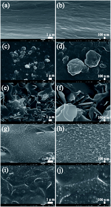 | ||
| Fig. 2 SEM micrographs of pure PI (a) and (b); PI nanocompostite films with h-BN (c) and (d); Gh-BN (e) and (f); EPPOSS (g) and (h); EPPOSS@Gh-BN (i) and (j). | ||
Furthermore, in order to investigate the alignment of modified BN in PI composite film, a comparative investigation with 3 wt% EPPOSS@Gh-BN and h-BN was performed. The PI in the fracture interface of the PI/EPPOSS@Gh-BN film is interconnected, with fracture surface branches that are dense and fibre-like, as shown in Fig. S2(a),† while the filler and the matrix are in close contact, forming a superimposed state with the PI under the action of EPPOSS, as shown in Fig. S2(b).† Fig. S2(c)† shows that the PI fracture interface is rough, the h-BN filler contacts the matrix poorly, and the filler orientation is different and irregular.
3.3. Mechanical properties
The mechanical properties of particle-filled polymer composites depend on the efficiency of the stress transfer across the interface between the matrix and filler.44 Fig. 3(a) shows that, at the same h-BN content of 0.2 wt%, PI/EPPOSS@Gh-BN (0.2 wt% Gh-BN with 0.1 wt% EPPOSS), PI/Gh-BN, and PI/EPPOSS (0.1 wt%) exhibit higher tensile strengths than pure PI, while that of PI/h-BN is lower. In particular, PI/EPPOSS@Gh-BN is stronger than PI/Gh-BN due to the good dispersion of the EPPOSS@Gh-BN fillers in the PI matrix, indicating that EPPOSS can act as an efficiency intermediary between PI and Gh-BN to promote the compatibility of the two materials. In addition, thickness dependent tensile strength and TGA of PI/EPPOSS@Gh-BN were evaluated (Fig. S3†).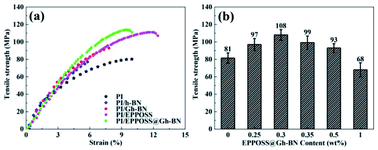 | ||
| Fig. 3 Tensile strengths of PI nanocomposite films with different fillers (a) and PI/EPPOSS@Gh-BN with different filler contents (b). | ||
Fig. 3(b) shows the effect of the EPPOSS@Gh-BN content on the tensile strength of the PI nanocomposite films. The tensile strengths of the PI/EPPOSS@Gh-BN nanocomposite films initially increased with increasing EPPOSS@Gh-BN content (0.25 and 0.3 wt%) and then decreased with further increases. The PI/EPPOSS@Gh-BN nanocomposite films with 0.3 wt% EPPOSS@Gh-BN exhibited an average tensile strength of 108 MPa, and the highest mechanical strength of 114 MPa, which is 40% higher than that of pure PI. And the PI/EPPOSS@Gh-BN in Fig. S4(c)† exhibits an excellent storage modulus, which is 4 GPa at room temperature, more than 30% higher than that of pure PI. The addition of a low content of Gh-BN, EPPOSS or nanocomposite fillers did not show favorable effect on Tg of the PI (Fig. S4(b)†), this is consistent with the differential scanning calorimetry (DSC) curves in Fig. S4(a).† Furthermore, the CTE of PI/EPPOSS@Gh-BN (CTE = 6.33 × 10⁻⁵ °C) is marginally lower than that of pure PI, which is because of the improved chain orientation of PI by Gh-BN (Fig. S5†). It is therefore evident that appropriate amounts of EPPOSS@Gh-BN (≤0.5 wt%) can effectively transfer the stress and prevent cracking under external forces, improving the tensile strengths of the PI/EPPOSS@Gh-BN nanocomposite films.
3.4. Dielectric properties
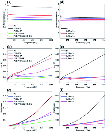
Fig. 4 depicts the dielectric constants, dielectric losses, and electrical conductivities of the PI and PI nanocomposite films as a functions of the RF frequency. Fig. 4(a) shows that the dielectric constants of PI/Gh-BN (0.2 wt% Gh-BN) are higher than those of PI, whereas PI/EPPOSS (0.1 wt% EPPOSS) and PI/EPPOSS@Gh-BN (0.2 wt% Gh-BN with 0.1 wt% EPPOSS) have lower dielectric constants than PI. This finding can be attributed to the agglomeration of Gh-BN in the polymer matrix, where the organic functional groups present on h-BN enhance the possibilities of polarization and moisture absorption.47 The decrease is largely dependent on the EPPOSS modification with a nano-porous structure because porosity will always lead to a lower dielectric constant as air has the lowest dielectric constant among all materials.48–50 Moreover, PI/EPPOSS@Gh-BN shows the lowest measured values of electrical conductivities and dielectric losses in the range of 10 MHz, as shown in Fig. 4(b) and (c). The dielectric loss tangent is closely associated with the electrical conductivity of the polymer matrix, which is determined by the dipole concentration and charge carrier density in the materials.51 This characteristic may be due to the hindrance caused by the EPPOSS-modified Gh-BN, which is well intercalated and dispersed in the polymer matrix and further lowers the electrical conductivity. Fig. 4(d)–(f) depict the electrical properties of PI/EPPOSS@Gh-BN with different EPPOSS@Gh-BN contents. Both the dielectric constants and dielectric losses of the PI/EPPOSS@Gh-BN nanocomposite films are significantly lower than those of the original PI resin throughout the frequency range. As the content of EPPOSS in the PI matrix increases, the introduction of air in PI leads to dielectric constant and dielectric loss of PI/EPPOSS@Gh-BN to decrease gradually. Specifically, as POSS provides the nanocomposites with superior characteristics, the dielectric constant, electrical conductivity, and dielectric loss of PI/EPPOSS@Gh-BN are significantly lower than those of pristine PI throughout the frequency range.3.5. Thermal conductivity
The hot disk transient flat heat source method was used to test the thermal conductivities of the prepared composite films, and the probe was placed between the two samples, to test the thermal conductivity within 1 s, and at the temperature point of 50 °C. The thermal conductivities and thermal diffusivities of the PI and PI nanocomposite films are depicted in Fig. 5. The thermal conductivities of the Gh-BN (0.2 wt%), EPPOSS (0.1 wt%), and EPPOSS@Gh-BN (0.3 wt%) filled PI nanocomposite films exhibit slight improvement compared to that of the pure PI film, with enhancements of 6%, 3%, and 9%, respectively. The thermal diffusivity of the PI/EPPOSS@Gh-BN nanocomposite film is higher than that of pure PI, whereas the PI/Gh-BN and PI/EPPOSS films are lower than that of pure PI because of the accumulation of h-BN in the matrix, which increased the interface thermal resistance and further reduced the thermal diffusivity.51 Similar to the mechanical behaviour, the EPPOSS-modified Gh-BN exhibited a higher thermal conductivity than h-BN, which may be attributed to the good dispersion of BN platelets in the PI matrix originating from the surface treatment, which reduces the scattering of phonons and improves the thermal diffusion ability.52,53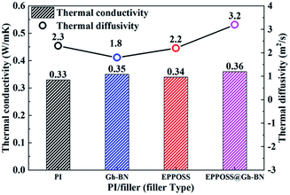 | ||
| Fig. 5 Thermal conductivity and thermal diffusivity of the PI nanocomposite films as a function of filler type. | ||
3.6. Thermal stability
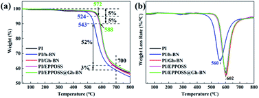
To evaluate the thermal stability of the PI nanocomposite films, TGA and DTG plots of the PI films are shown in Fig. 6. As can be seen, the thermal stabilities of the PI/Gh-BN (0.2 wt%) and PI/EPPOSS (0.1 wt%) films with low filling amounts are lower than that of pure PI. At 700 °C, the residual weight ratio of the PI/EPPOSS@Gh-BN (0.3 wt%) film can reach 57% with faster decomposition rate in the DTG curve. Further, the addition of a low content of Gh-BN or EPPOSS to the PI does not affect the weightlessness temperature of the nanocomposite film, but PI/h-BN reduces the weight loss temperature (T5% decreases by more than 50 °C, T10% and Tmax decrease by approximately 40 °C). Consequently, the weight loss temperatures of the PI/EPPOSS@Gh-BN nanocomposite fillers increase (T5% increases by 3 °C, T10% increases by 2 °C), due to the homodispersion of the EPPOSS@Gh-BN nanocomposite filler in the matrix. According to the DTG plots in Fig. 6(b), the maximum decomposition temperatures (Tmax) for the PI, PI/Gh-BN, PI/EPPOSS, and PI/EPPOSS@Gh-BN nanocomposite films are all higher than 600 °C. However, the thermal performance of PI/h-BN is significantly lower than that of pure PI; which is believed to be due to the poor compatibility between h-BN and the matrix, which blocked the aromatic ring structure of PI and reduced the thermal performance.3.7. Infrared thermal imaging test
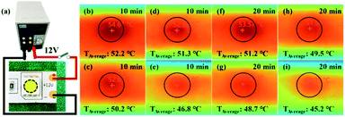
Furthermore, to verify the heat management ability of the PI/EPPOSS@Gh-BN nanocomposite films for electronic devices, the PI nanocomposite film was utilized as a substrate to bond to 12 V LED strips (Fig. 7(a)). The temperature distributions of the LED strips were detected by Fluke infrared thermal cameras. The Fluke Connect tools can calculate the maximum and average temperatures of the surrounding area of the center LED. Fig. 7(b), (c), (d) and (e) show that when the LED is lit and operated for 10 min, the mean temperatures surrounding the LED chip of pure PI, PI/Gh-BN, PI/EPPOSS and PI/EPPOSS@Gh-BN were 52.2, 50.2, 51.3 and 46.8 °C, respectively. The average temperature of the PI/EPPOSS@Gh-BN-based LEDs was lower than that of other base LEDs. After 20 min of operation, the surface temperature tended to be stable and the mean temperatures surrounding the LED chip of pure PI, PI/Gh-BN, PI/EPPOSS and PI/EPPOSS@Gh-BN-based LEDs were 51.2, 48.7, 49.5 and 45.2 °C, respectively, suggesting better heat transfer performance of the PI/EPPOSS@Gh-BN film. These results significantly agree with the thermal conductivity results. The PI/EPPOSS@Gh-BN nanocomposite film was observed to effectively dissipate heat and to exhibit a wide range of applications in thermal management.3.8. Hydrophobicity
The propensity of polymer composites to absorb water is a very significant problem that can drastically deteriorate the dielectric, mechanical, and other properties of these composites. Fig. 8 shows that the contact angles of EPPOSS@Gh-BN (0.2 wt% Gh-BN with 0.1 wt% EPPOSS), PI/Gh-BN, PI/h-BN, and PI/EPPOSS (0.1 wt%) with the same h-BN content of 0.2 wt% and PI/EPPOSS@Gh-BN with different filler contents. The contact angle of the pristine polymer exhibits the lowest value, whereas that of PI/EPPOSS@Gh-BN has the best value (approximately 95°) due to the synergistic hydrophobic effect of EPPOSS and h-BN. Further, the contact angle remained above 90° when EPPOSS@Gh-BN was loaded (red line); notably, the dielectric constant can be reduced when the contact angle is maintained above 90°. These results are in good agreement with the dielectric results. It was seen that the hydrophobic properties of the PI/EPPOSS@Gh-BN nanocomposite film can prevent the circuit board from being damaged by water conduction and therefore has a wide range of applications in the modern circuit and electronics industry.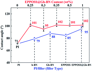 | ||
| Fig. 8 Contact angles of the PI nanocomposite films with different fillers and PI/EPPOSS@Gh-BN with different filler contents. | ||
4. Conclusion
In this study, we designed and synthesized EPPOSS functionalized KH550-modified h-BN to achieve improved mechanical properties. When EPPOSS@Gh-BN was filled with 0.3 wt%, the highest mechanical strength of the films was 114 MPa, which is more than 40% of that of pure PI. And the storage modulus of 4 GPa was increased by more than 30% compared to pure PI. Meanwhile, lower dielectric properties, improved thermal conductivity and thermal diffusivity, and better heat transfer performance could be obtained with the PI nanocomposites, which showed excellent comprehensive properties. These results demonstrate that EPPOSS can effectively improve the compatibility between PI and h-BN, and that EPPOSS@Gh-BN can therefore effectively improve the comprehensive performance of PI at low filling content, expanding the wide range of application of multifunctional PI polymer-based nanocomposites.Conflicts of interest
There are no conflicts to declare.Acknowledgements
This work was supported by the National Natural Science Foundation of China (Grant No. 51927806), Science and Technology Planning Project of 2020 Beijing Education Commission (KM202010015006).References
- G. Qiu, W. Ma and L. Wu, Polym. Int., 2020, 69, 485–491 CrossRef CAS.
- Z. Wang, G. Fang, J. He, H. Yang and S. Yang, React. Funct. Polym., 2020, 146, 104411 CrossRef CAS.
- E. Sugimoto, IEEE Electr. Insul. Mag., 2002, 5, 15–23 Search PubMed.
- X. Huang, Z. Ding, J. Wang, J. Wang and Q. Li, ACS Appl. Electron. Mater., 2020, 2, 3418–3425 CrossRef CAS.
- F. Yang, X. Zhao, T. Xue, S. Yuan, Y. Huang, W. Fan and T. Liu, Sci. China Mater., 2020, 64, 1267–1277 CrossRef.
- Y. Zhang, H. Wu, Y. Guo, Y. Yang, Q. Yu, J. Liu, B. Wu and F. Lv, Nanomaterials, 2021, 11, 141 CrossRef CAS PubMed.
- R. Revathi, P. Prabunathan and M. Alagar, Polym. Bull., 2018, 76, 387–407 CrossRef.
- D. Ding, Z. Shang, X. Zhang, X. Lei, Z. Liu, Q. Zhang and Y. Chen, Ceram. Int., 2020, 46, 28363–28372 CrossRef CAS.
- Y. Yang, J. Gao, T. Lei, J. Yang, J. Wang and J. Liu, Polym. Eng. Sci., 2020, 60, 1044–1053 CrossRef CAS.
- J. An, E. J. Lee, B. J. Kim, H. J. Kim, Y. J. Kim, J. Shim and I. Hong, Mater. Lett., 2015, 161, 321–324 CrossRef CAS.
- R. Li, C. Ding, J. Yu, X. Wang and P. Huang, High Perform. Polym., 2021, 33, 905–913 CrossRef CAS.
- Y. Qian, Y. Lan, J. Xu, F. Ye and S. Dai, Appl. Surf. Sci., 2014, 314, 991–999 CrossRef CAS.
- X. Wu, Y. Zhang, P. Du, Z. Jin, H. Zhao and L. Wang, New J. Chem., 2019, 43, 5697–5705 RSC.
- B. Govindaraj and M. Sarojadevi, Polym. Adv. Technol., 2018, 29, 1718–1726 CrossRef CAS.
- W. Yan, Y. Zhang, H. Sun, S. Liu, Z. Chi, X. Chen and J. Xu, J. Mater. Chem. A, 2014, 2, 20958–20965 RSC.
- J. Lim, D. G. Shin, H. Yeo, M. Goh, B. Ku, C. Yang, D. S. Lee, J. Hwang, B. Park and N. You, J. Polym. Sci., Part B: Polym. Phys., 2014, 52, 960–966 CrossRef CAS.
- T. Wang, M. Wang, L. Fu, Z. Duan, Y. Chen, X. Hou, Y. Wu, S. Li, L. Guo, R. Kang, N. Jiang and J. Yu, Sci. Rep., 2018, 8, 1557 CrossRef PubMed.
- M. Haruki, J. Tada, R. Funaki, H. Onishi and Y. Tada, Thermochim. Acta, 2020, 684, 178491 CrossRef CAS.
- H. Qi, G. Zhang, Z. Zheng, J. Yu and C. Hu, Friction, 2020, 9, 301–314 CrossRef.
- J. An and Y. G. Jeong, Eur. Polym. J., 2013, 49, 1322–1330 CrossRef CAS.
- L. Nayak, M. Rahaman, A. Aldalbahi, T. K. Chaki and D. Khastgir, Polym. Eng. Sci., 2017, 57, 291–298 CrossRef CAS.
- Y. Liu, S. Bhowmick and B. I. Yakobson, Nano Lett., 2011, 11, 3113–3116 CrossRef CAS PubMed.
- G. Satta, G. Cappellini, M. Palummo and G. Onida, Comput. Mater. Sci., 2001, 22, 78–80 CrossRef CAS.
- A. Pakdel, Y. Bando and D. Golberg, Chem. Soc. Rev., 2014, 43, 934–959 RSC.
- M. Xu, T. Liang, M. Shi and H. Chen, Chem. Rev., 2013, 113, 3766–3798 CrossRef CAS PubMed.
- R. Yang, M. Sheng, Y. Zhang, H. Gong, X. Lin, Y. Pei and X. Zhang, High Perform. Polym., 2020, 33, 417–428 CrossRef.
- H. Cho, T. Nakayama, H. Suematsu, T. Suzuki, W. Jiang, K. Niihara, E. Song, N. S. A. Eom, S. Kim and Y. Choa, Compos. Sci. Technol., 2016, 129, 205–213 CrossRef CAS.
- A. M. Satawara, G. A. Shaikh, S. K. Gupta and P. N. Gajjar, Mater. Today: Proc., 2021, 47, 529–532 CAS.
- I. Miyazato, T. Hussain and K. Takahashi, J. Mater. Chem. C, 2020, 8, 9755–9762 RSC.
- Q. Chi, Z. Gao, T. Zhang, C. Zhang, Y. Zhang, Q. Chen, X. Wang and Q. Lei, ACS Sustainable Chem. Eng., 2018, 7, 748–757 CrossRef.
- S. Cheng, Y. Zhou, J. Hu, J. He and Q. Li, IEEE Trans. Dielectr. Electr. Insul., 2020, 27, 498–503 CAS.
- T. Fei, Y. Li, B. Liu and C. Xia, High Perform. Polym., 2019, 32, 324–333 CrossRef.
- H. L. Lee, O. H. Kwon, S. M. Ha, B. G. Kim, Y. S. Kim, J. C. Won, J. Kim, J. H. Choi and Y. Yoo, Phys. Chem. Chem. Phys., 2014, 16, 20041–20046 RSC.
- B. Pukánszky, Composites, 1990, 21, 255–262 CrossRef.
- C. Kizilkaya, Y. Mülazim, M. V. Kahraman, N. K. Apohan and A. Güngör, J. Appl. Polym. Sci., 2012, 124, 706–712 CrossRef CAS.
- J. Gu, Q. Zhang, J. Dang and C. Xie, Polym. Adv. Technol., 2012, 23, 1025–1028 CrossRef CAS.
- J. Song, Z. Dai, J. Li, H. Zhao and L. Wang, High Perform. Polym., 2017, 31, 116–123 CrossRef.
- S. Kim, T. Liu and X. Wang, ACS Appl. Mater. Interfaces, 2015, 7, 20865–20874 CrossRef CAS PubMed.
- Z. He, J. Xie, Z. Liao, Y. Ma, M. Zhang, W. Zhang, H. Yue and X. Gao, Prog. Org. Coat., 2021, 151, 106030 CrossRef CAS.
- C. Huang, J. Li, G. Xie, F. Han, D. Huang, F. Zhang, B. Zhang, G. Zhang, R. Sun and C. Wong, Macromol. Mater. Eng., 2019, 304, 1900505 CrossRef CAS.
- K. Mishra, G. Pandey and R. P. Singh, Polym. Test., 2017, 62, 210–218 CrossRef CAS.
- Y. Guo, Z. Lyu, X. Yang, Y. Lu, K. Ruan, Y. Wu, J. Kong and J. Gu, Composites, Part B, 2019, 164, 732–739 CrossRef CAS.
- C. Qu, Y. Tang, D. Wang, X. Fan, H. Li, C. Liu, K. Su, D. Zhao, J. Jing and X. Zhang, J. Appl. Polym. Sci., 2020, 138, 49640 CrossRef.
- G. Li, R. Xing, P. Geng, Z. Liu, L. He, N. Wang, Q. Zhang and X. Qu, Polym. Adv. Technol., 2018, 29, 337–346 CrossRef CAS.
- J. Thomas, N. E. Weston and T. E. O'Connor, J. Am. Chem. Soc., 1962, 84, 4619–4622 CrossRef CAS.
- S. Kim, S. Ando and X. Wang, RSC Adv., 2015, 5, 40046–40054 RSC.
- D. Yang, Y. Ni, X. Kong, H. Xue, W. Guo and L. Zhang, Appl. Surf. Sci., 2019, 495, 143638 CrossRef.
- S. Kim, X. Wang, S. Ando and X. Wang, RSC Adv., 2014, 4, 27267–27276 RSC.
- T. Seçkin, S. Köytepe and H. İ. Adıgüzel, Mater. Chem. Phys., 2008, 112, 1040–1046 CrossRef.
- C. Zhang, S. Guang, X. Zhu, H. Xu, X. Liu and M. Jiang, J. Phys. Chem. C, 2010, 114, 22455–22461 CrossRef CAS.
- X. Huang, C. Zhi, P. Jiang, D. Golberg, Y. Bando and T. Tanaka, Adv. Funct. Mater., 2013, 23, 1824–1831 CrossRef CAS.
- R. J. Warzoha and A. S. Fleischer, Nano Energy, 2014, 6, 137–158 CrossRef CAS.
- Y. Yao, X. Zeng, K. Guo, R. Sun and J. Xu, Composites, Part A, 2015, 69, 49–55 CrossRef CAS.
Footnote |
| † Electronic supplementary information (ESI) available. See DOI: 10.1039/d2ra00267a |
| This journal is © The Royal Society of Chemistry 2022 |

