 Open Access Article
Preparation of a carbon fibre-reinforced carbon aerogel and its application as a high-temperature thermal insulator
Haiming Zhanga,
Junzong Fengb,
Liangjun Lib,
Yonggang Jiangb and
Jian Feng *b
*b
aInstitute of Applied Physics, Jiangxi Academy of Science, Nanchang 330096, China
bScience and Technology on Advanced Ceramic Fibres and Composites Laboratory, College of Aerospace Science and Engineering, National University of Defense Technology, Deya Road 109, Changsha, 410073, Hunan, China. E-mail: fengj@nudt.edu.cn
First published on 9th May 2022
Abstract
Carbon aerogels (CAs) have attracted attention in thermal insulation. However, the traditional sol–gel method for preparing them involves time-consuming solvent exchange and rigorous supercritical drying processes, and the obtained CAs are brittle and crumble easily. To address these problems, a carbon fibre-reinforced carbon aerogel (CF/CA) was prepared via combining a resorcinol–furfural (RF) gel containing a salt (ZnCl2) with polyacrylonitrile (PAN) fiber felt. The CF/CA not only has low thermal conductivity (0.6904 W m−1 K−1) even at an ultra-high temperature of 1800 °C in an argon atmosphere but also exhibits relatively high compressive strength (6.10 MPa, 10% ε) and a low density of 0.68 g cm−3. The CF/CAs can be used as ultrahigh-temperature thermal insulators (under inert atmospheres or vacuum) in thermal protection systems such as space vehicles or industrial high temperature furnaces. Our novel strategy may lead to lower-cost and large scale industrial processes of CF/CAs.
1. Introduction
Among all aerogels to date,1–9 carbon aerogels (CAs) have the highest thermal stability and can maintain their unique nanoporous structure even at temperatures as high as 2000 °C under inert atmospheres.10–12 This high thermal stability of CAs, combined with excellent thermal insulation properties and low density, makes CAs promising candidates for ultrahigh temperature thermal insulation in thermal protection systems such as space vehicles or industrial high temperature furnaces.13,14 However, CAs are brittle and fragile,15 the mechanical properties of CAs can be improved by reinforcing them with fibres to form carbon fibre–carbon aerogel composites (CF/CAs).16,17 The traditional sol–gel method for preparing CF/CAs involves solvent-exchange and supercritical-fluid drying processes,18–22 organic waste liquids from the solvent-exchange process pollute the environment,23 moreover, the supercritical-fluid drying process demands high-temperature and pressure conditions,24,25 thereby increasing the safety risk and production costs.26,27Many attempts have been made to prepare CAs by ambient drying.28–31 For example, highly porous carbon was prepared using glucose as carbon precursor and eutectic of lithium chloride/zinc chloride as porogen, appearing as powder.28 Hierarchical porous functional carbon was prepared by using ionic liquids as carbon precursor and eutectic mixture of LiCl/ZnCl2 as salt template, the hierarchical porous carbon also appears as powder.29 Mesoporous carbon aerogel was prepared by using calcium carbonate particles as salt template under ambient pressure drying, but the carbon precursor gel was subjected to solvent-exchange several times with petroleum ether.30 Phenolic polymer-derived CA was prepared by direct polymerisation of reactive monomers phenol and formaldehyde under hypersaline conditions using ZnCl2 salt, the phenol–formaldehyde–ZnCl2 monolith was transformed into a foamy during the simultaneous carbonization and foaming processes, the foamy CA possess micron-sized macropores and cannot be used as a matrix for thermal-insulating CF/CA.31 In practice, it is a challenge to prepare CF/CAs for thermal insulation by ambient pressure drying.32–36
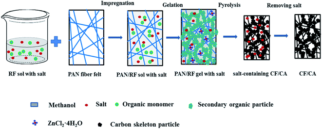
In this study, CF/CA for thermal insulation was prepared by impregnating polyacrylonitrile (PAN) fibre felts with resorcinol (R)–furfural (F) sol containing salt (ZnCl2), followed by ageing and pyrolysis. The RF sol containing salt was synthesized by direct polymerisation of R and F in methanol (MeOH) using ZnCl2 as a salt template. Herein, salt template is acted as dehydration and porogens, a portion of salt combines with water molecules generated by the reaction of R and F to form ZnCl2·4H2O during the sol–gel process,37 the RF gel with salt undergoes sufficient polycondensation reaction, thus enhancing the nano-skeleton strength of RF gel, the obtained CF/CA did not shrink largely during the carbonization process owing to its strengthness and the support of salt template. After carbonization, the salt template could be easily removed with water, the robust carbon skeleton can withstand the capillary force related to the surface tension of water during ambient pressure drying, thereby opening up abundant micropores and few mesopores in the CF/CA.38–40 Abundant nanopores (pore size less than 69 nm) are efficient in reducing the total thermal conductivity by reducing the gaseous thermal conductivity,41 moreover, the obtained CF/CA has significantly increased mechanical properties. Compared with the traditional sol–gel method for preparing CF/CAs,41–44 this procedure eliminates the need for solvent-exchange and supercritical-fluid drying processes. To our knowledge, the preparation of CF/CAs via combining RF gel containing salt with PAN fiber felts has not been reported.
2. Experimental section
2.1 Materials
The reactive monomers, including R and F, ZnCl2 and MeOH were supplied by Sinopharm Chemical Reagent Co. Ltd. Hexamethylenetetramine (HTM) was supplied by Tianjin Wind Boat Chemical Reagent Technology Co. Ltd. The polyacrylonitrile (PAN) fibre felt was purchased from Nantong Senyou Carbon Fibre Co. Ltd. The chemical reagents were obtained as analytical grade and used without any further purification.2.2 Fabrication of carbon fibre-reinforced carbon aerogel
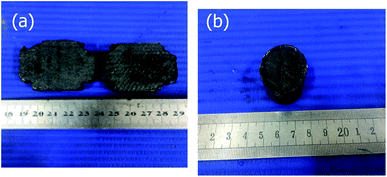
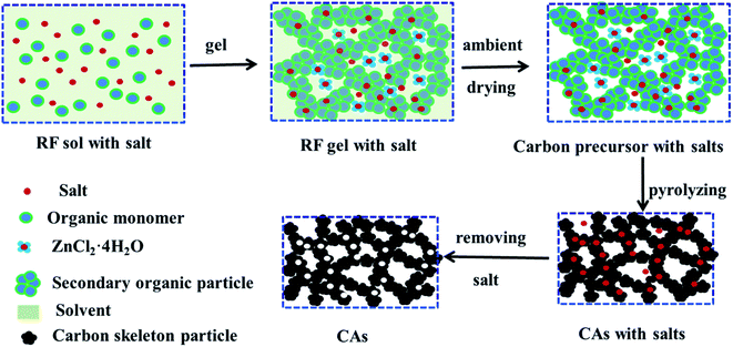
Carbon fiber reinforced carbon aerogel (CF/CA) was prepared by pyrolysis of resorcinol–furfural (RF) gel containing salt (ZnCl2) reinforced by PAN fiber felts. Firstly, RF gel containing salt was synthesised via the sol–gel process using R and F as monomers, MeOH as solvent, HMT as catalyst, and ZnCl2 as salt template. The flow chart for the preparation process is shown in Fig. 1. The F/R, HTM/R, MeOH/R and ZnCl2/R molar ratios were 2, 0.024, 12 and 1.0, respectively. After thoroughly blending the chemical reagents, RF sol with salt was obtained. Then, PAN/RF sol with salt was prepared by impregnating PAN fibre felt (apparent density: 0.12 g cm−3) with RF sol with salt under vacuum. The PAN/RF sol with salt was sealed with a plastic film and immersed in a 50 °C water bath pot for 24 h. RF sol with salt undergoes sufficient chemical cross-linking reaction during aging treatment and transforms into a RF gel with salt, which exhibits high mechanical strength. The PAN/RF gel with salt was carbonized directly at 650 °C for 2 h under nitrogen flow (200 ml min−1) with a heating rate of 2.5 °C min−1. The obtained salt-containing CF/CA was soaked in deionised water to remove salt template and dried in ambient pressure, then, the CF/CA (Fig. 2a) was obtained. CA (Fig. 2b) was also prepared by pyrolysing RF gel with salt under the same condition of preparing CF/CA.2.3 Characterizations
The linear shrinkage rate (Lshri) of the samples was calculated from the dimension of the samples before and after carbonization according to eqn (1). Dbefore and Dafter refer to the radial diameter of the samples before and after carbonization process.
 | (1) |
The bulk densities of the CA or CF/CA were obtained by measuring the mass and corresponding volume. The weight change of the PAN/RF gel with salt during carbonization under a flowing argon atmosphere was investigated by a NETZSCH STA 449F3 thermogravimetric (TG) analyzer, the heating rate was 10 °C min−1, and the heating temperature range was from room temperature up to 1500 °C, the thermal stability of the CA in air atmosphere was investigated by TG (NETZSCH STA 449F3 thermogravimetric analyzer). The pore properties of the CA and CF/CA were determined by a 3H-2000PM2 apparatus from BeiShiDe Instrument, the specific surface area of the samples was calculated by applying Brunauer–Emmett–Teller (BET) method. The Barrett–Joyner–Halenda (BJH) model was applied to calculate the total pore volume from the adsorption–desorption isotherms. Pore size distribution curves were calculated by NLDFT method from the desorption branches. Horvath–Kawazoe (H–K) theory also was applied to derive pore size distribution. The microstructure of the samples were investigated by A Hitachi S-4800 scanning electron microscopy (Japan) after being coated with a thin gold layer. The microstructure surface of the CF/CA and CA were investigated using Tecnai G2 F20 S-TWIN field emission transmission electron microscope (TEM) system, the samples were ground and dispersed with ethanol before placing it on a copper grid and analyzing them at 300 kV. X-ray photoemission spectroscopy (XPS; ESCALAB 250Xi) and CHN element analysis were applied to determine element percentages of the CF/CA. The crystal phase structure of the CAs prepared at different temperatures were characterized by a D8 Advance X-ray diffraction (XRD) apparatus using Cu Kα radiation with a Ni filter. Raman spectroscopy (Renishaw RM2000) was used to examine the graphitization degree of the CAs prepared at different temperature. The compression strength of the CF/CA was tested by universal testing machine (WDW model 100) with sample dimensions of 15 × 15 × 15 mm. The CF/CA was cut into cube-shape with diameters of 10 mm and thicknesses of approximately 2.0 mm, the thermal diffusivity (α) in the through-plane direction of the samples was determined by laser flash method using a Netzsch LFA 427 apparatus in argon atmosphere, the thermal conductivity (λ) was obtained according to eqn (2).45
| λ = α(T)ρcp(T) | (2) |
3. Results and discussion
3.1 Thermogravimetric analysis
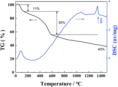
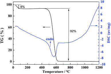
The weight change of the PAN/RF gel with salt during heat treatment process was investigated by TG-DSC under a flowing argon atmosphere, the heating rate was 10 °C min−1, and the heating temperature range was from room temperature up to 1500 °C. The weight loss curve during heat treatment process is shown in Fig. 3. The weight change is 62% in the temperature range from room temperature up to 1500 °C. Firstly, it can be seen that a weight loss (11%) takes place in the range from room temperature to 160 °C, which is due to the evaporation of methanol solvent as well as the evaporation of water molecules generated from the reaction of resorcinol and furfural. Secondly, a larger weight loss (35%) is observed in the temperature range from 160 to 600 °C, which is attributed to the release of some gas molecules in the pyrolysis process of PAN/RF gel with salt. Finally, a fairly small weight loss (only 16%) is observed in the temperature range from 600 °C to 1500 °C, which is mainly attributed to the continuous pyrolysis carbonization of organic group and the evaporation of some zinc chloride. In addition, DSC curve shows one exothermic peak in the two temperature intervals of 80–120 °C and 1300–1400 °C, respectively.In order to study the thermal stability of the CA in air atmosphere, the weight change of the CA during heat treatment process was investigated by TG-DSC under a flowing air atmosphere, the heating rate is 5 °C min−1, and the heating temperature range is from room temperature to 1200 °C. The TG-DSC curves of CA in air atmosphere is shown in Fig. 4. Firstly, it can be seen that a weight loss (8%) takes place in the range from room temperature to 100 °C, which is due to the evaporation of residual water in the CA. When the heating temperature increases to 450 °C, the CA begins to be oxidized in air atmosphere, a significantly larger weight loss (92%) is observed for CA in the range from 450 to 620 °C. In addition, DSC curve shows one endothermic peak in the temperature interval of 450–620 °C.
3.2 Porous structure characterization
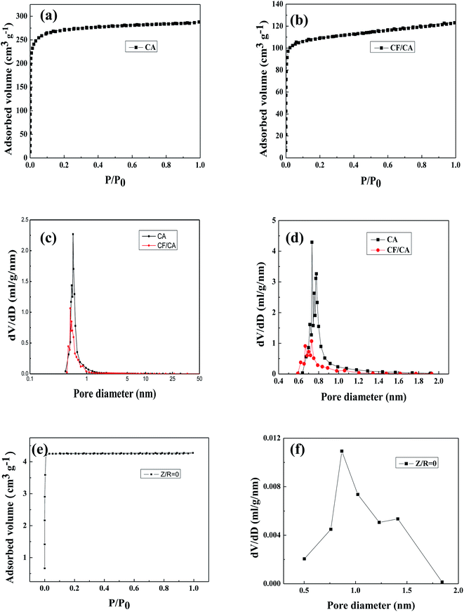
The N2 adsorption–desorption isotherm curve and pore size distribution curves in Fig. 5 are used to analyze the porous structure of CA without salt, CA and CF/CA. According to classification of IUPAC, both the isotherm curves (Fig. 5a and b) are similar and exhibit a typical feature of type-I isotherm, which infers that microporous adsorption potential energy is very large and microporous specific surface area is much larger than external specific surface area. A sharp rise of the N2 adsorption–desorption isotherm curves at low relative pressure scope (P/P0 ≦ 0.01) infers the presence of abundant microporous, which is in agreement with the nanoporous structure parameters of CA and CF/CA shown in Table 1. From the micropore size distribution curves depending on NL-DFT model (Fig. 5c), it can be seen that the modal peaks occur at a pore size diameter of 0.8 nm and the pore sizes are focused in a range of 0.5–1.8 nm for the CA and CF/CA. Fig. 5d shows the pore size distribution curves of CA and CF/CA derived from the H–K method, the pore sizes are focused in a range of 0.6–1.6 nm for the CAs and CF/CA, the modal peak value appears at 0.7 nm. Fig. 5e shows the N2 adsorption–desorption isotherms curves of CA without salt, the isotherm curves exhibit IUPAC type-I curves, an abrupt but small rise of adsorbed volume at a very low relative pressure (P/P0 < 0.1), indicating the presence of a little microporous. Fig. 5f shows the pore size distribution curves of CA without salt derived from the H–K method, the pore sizes are focused in a range of 0.5–1.8 nm and the modal peak value occurs at about 0.8 nm for the CA without salt.| Sample | SBET (m2 g−1) | Smicro (m2 g−1) | Sext (m2 g−1) | Vpore (cm3 g−1) | Dpore (nm) |
|---|---|---|---|---|---|
| CA without salt | 15.69 | 15.69 | 0 | 0.006 | 1.68 |
| CA | 818.98 | 815.44 | 3.54 | 0.327 | 1.60 |
| CF/CA | 425.66 | 405.74 | 19.92 | 0.190 | 1.78 |
Table 1 lists the BET surface area and nanoporous structure parameters of CA without salt, CA, and CF/CA. The BET specific surface area of CA was 818.98 m2 g−1, the BET surface area is mainly composed of microporous specific surface area. ZnCl2 salt plays a key role in the microporous formation of CA, serving as dehydration agent and porogen. A portion of the salt combines with water molecules generated by the reaction of R and F to form ZnCl2·4H2O crystal during the sol–gel process. A part ZnCl2 salt is embedded in the RF gel skeleton, the other part of ZnCl2 salt and ZnCl2·4H2O crystal are dispersed in the nanopores of the RF gel. After pyrolysis, removing salt with water and drying at ambient pressure, thereby opening up abundant microporous and few mesoporous in CA and CF/CA. The nanopore formation mechanism via salt template is shown in Fig. 6. The total pore volume and BET specific surface area of CA are much higher than that of CF/CA, which is mainly attributed to the introduction of carbon fibres, carbon fibres possess negligible pore volume and specific surface area coMPared with CA. The mean pore sizes of CA and CF/CA are similar. The external specific surface of CF/CA is slightly bigger than that of CA. In contrast, the synthesis of CA without salt only result in dense structures, the specific surface area of CA without salt was 15.69 m2 g−1, which was completely composed of microporous specific surface area, and its pore volume is 0.006 cm3 g−1. Thus, the absent of mesoporous or macroporous structure in CA without salt is determined by the intrinsic property of resorcinol–furfural (RF) gel.
3.3 SEM and TEM observation
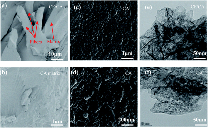
The SEM images of CF/CA and CA are shown in Fig. 7(a–d). Fig. 7a shows that an important feature of CF/CA is the tightly integration between carbon fibre reinforcement and matrix, the matrix fill in the space among carbon fibres, separating carbon fibres from one another, and enveloping them. Fig. 7b shows that there are not any micron macropores and obvious cracks in the matrix of CF/CA, the CA matrix has uneven surface. The uneven surface of the CA was consisted of carbon nanoflakes, the carbon nanoflakes size are focused in a range of 20–30 nm, which were interconnected to form a 3D nanoporous network structure, as shown in the high magnification SEM (Fig. 7c and d). The TEM micrographs of the CF/CA and CA are shown in Fig. 7d and e, there was no apparent difference in the microtexture between the CF/CA and CA, they have a similar three-dimension nanoporous network structure, the solid phase is composed of interconnected particles with diameter less than 5 nm, the nanopore size is smaller than 5 nm.3.4 Optical images, XRD patterns, and Raman spectra of the CAs
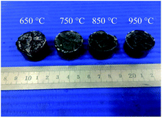
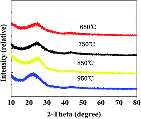
The optical images of the CAs prepared at different temperatures are shown in Fig. 8. It can be seen that the surface of monolithic CAs prepared at different temperatures is similar and smooth, there are no micron-sized macropores.X-ray diffraction patterns of CAs prepared at different carbonization temperatures are shown in Fig. 9. There are not any sharp peaks, indicating that the CAs are basically amorphous. The two broad peaks in the diffraction patterns are corresponded to slightly disordered graphitic carbon at about 2θ = 23°and 2θ = 44°.
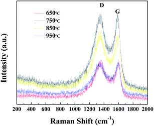
The Raman spectra of CAs prepared at different carbonization temperatures is shown in Fig. 10. Two typical peaks at around 1370 cm−1 and 1600 cm−1 are observed, matching with the disordered structure (D-band) and graphitic structure (G-band) of CAs, respectively. With the increase of temperature, the ID/IG values (1.026, 1.024, 1.027 and 1.022) for CAS prepared at different carbonization temperatures (650 °C, 750 °C, 850 °C, and 950 °C, respectively) hardly changed, indicating that the graphitization degree of CAs did not change in the carbonization temperature range from 650 to 950 °C.
3.5 Compositional anlysis
Elemental percentages of the CF/CA was analysed by XPS. Table 2 shows the elemental percentages of the CF/CA, the percentages of element such as carbon, nitrogen, oxygen, chlorine and zinc remaining in the CF/CA are 92.32%, 1.1%, 6.12%, 0.23%, and 0.23%, respectively. Because the residual salt could be easily removed with water, the residual salt content remaining in the CF/CA is extremely low, and they have almost no effect on the structure and properties of the CF/CA.| Element | C | N | O | Cl | Zn |
|---|---|---|---|---|---|
| Content (at%) | 92.32 | 1.1 | 6.12 | 0.23 | 0.23 |
Table 3 shows the percentage of elements of carbon, hydrogen and nitrogen remaining in the CF/CA. According to CHN element analysis, C, H, N, and O element percentages of the CF/CA are 87.54%, 2.66%, 1.05%, and 8.75%, respectively.
| Element | C | H | N | O |
|---|---|---|---|---|
| Content (at%) | 87.54 | 2.66 | 1.05 | 8.75 |
3.6 Compressive strength of the CF/CA
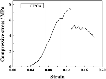
Fig. 11 shows the compression stress versus strain curve of the CF/CA. It can be seen that, for the CF/CA, the compressive stress versus strain curves show elastic deformation at the initial stage. The compression stress increases exponentially as the strain increases before the specimen is fractured, the compression stress is 6.10 MPa when the strain is 0.1. When the compressive stress of the CF/CA increases to the highest point, the CF/CA begins to fracture abruptly, then the compressive stress of the CF/CA decreases as the strain increases gradually, indicative of toughness fracture behavior of the CF/CA.47 The brittleness and fragility of CAs could be improved by reinforcing the CF/CA with PAN fibre felts.3.7 Thermal conductivities of the CF/CA
Table 4 shows the shrinkage and density of the CA and CF/CA, the linear shrinkage of CA is much higher than CF/CA during the carbonization process, the densities of the CA and CF/CA are 0.71 g cm−3 and 0.62 g cm−3, respectively.| Material | Linear shrinkage during carbonization (%) | Density (g cm−3) |
|---|---|---|
| CA | 25.14 | 0.71 |
| CF/CA | 12.16 | 0.62 |
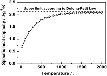
The specific heat is mainly related to the composition of the material, both CF/CA and CA are mainly composed of carbon. Therefore, the same specific heat is used for both CF/CA and CA when calculating thermal conductivity, the specific heat value of CF/CA was a known literature value of specific heat capacity.46 Fig. 12 shows that the specific heat values of CF/CA at different temperatures up to 2000 °C under argon, the specific heat values of CF/CA at the different measurement temperature (600 °C, 900 °C, 1200 °C, 1500 °C and 1800 °C) are 1.75 J g−1 K−1, 1.98 J g−1 K−1, 2.05 J g−1 K−1, 2.10 J g−1 K−1, 2.12 J g−1 K−1, respectively.
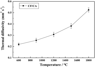
Fig. 13 shows the thermal diffusivities of the CF/CA at the measurement temperatures ranging from 600 °C to 1800 °C in argon atmosphere, the thermal diffusivities increase with increasing the temperature. The thermal diffusivities of CF/CA at the different measurement temperature (600 °C, 900 °C, 1200 °C, 1500 °C and 1800 °C) are 0.219 mm2 s−1, 0.255 mm2 s−1, 0.307 mm2 s−1, 0.382 mm2 s−1, 0.525 mm2 s−1, respectively.
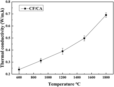
The thermal conductivity was obtained according to eqn (2) from the thermal diffusivity, the specific heat capacity and the density. Fig. 14 shows the thermal conductivities of the CF/CA at the temperatures ranging from 600 °C to 1800 °C in argon atmosphere. The thermal conductivities of the CF/CA increase gradually from 0.2381 W m−1 K−1 to 0.6904 W m−1 K−1 in the temperature interval of 600–1800 °C. Under the ultrahigh temperature 1800 °C and argon atmosphere, the thermal conductivity of the CF/CA (0.6904 W m−1 K−1) is only about one third of the value of the carbon foam (1.745 W m−1 K−1). In addition, the thermal conductivity of CF/CA studied by J. Feng is 0.328 W m−1 K−1 at 300 °C in air.45 The CF/CA can be used as a promising high-temperature thermal insulator (in inert atmospheres or vacuum) in thermal protection system.
4. Conclusions
In this study, we developed a novel preparation strategy of CF/CAs via combining RF gel containing salt with PAN fiber felts. Compared with the traditional sol–gel method for preparing CF/CAs, this procedure eliminates the need for solvent-exchange and supercritical-fluid drying processes. The obtained CF/CA exhibits low thermal conductivity (0.6904 W m−1 K−1) even at temperature as high as 1800 °C under argon atmosphere, and possess relatively high compressive strength (6.10 MPa, 10% ε) and a low density of 0.68 g cm−3. Thus, the CF/CAs can be used as promising candidates for ultrahigh temperature thermal insulation (under inert atmospheres or vacuum) in thermal protection systems such as space vehicles or industrial high temperature furnaces. Our novel strategy may lead to lower-cost and large scale industrial process for preparing CF/CAs.Conflicts of interest
There are no conflicts to declare.Acknowledgements
The authors sincerely acknowledge the financial support from National Natural Science Foundation of China (51702360) and Doctor Special Foundation of Jiangxi Academy of Sciences (2020-YYB-14).References
- Y. Hanzawa, H. Hatori, N. Yoshizawa and Y. Yamada, Carbon, 2002, 40, 575–581 CrossRef CAS.
- J. Zhao, C. Lai, Y. Dai and J. Xie, Mater. Lett., 2007, 61, 4639–4642 CrossRef CAS.
- A. Tiwari, A. P. Mishra, S. R. Dhakate, R. Khan and S. K. Shukla, Mater. Lett., 2007, 61, 4587–4590 CrossRef CAS.
- S. Budhi, H. S. Kibombo, D. Zhao, A. Gonshorowski and R. T. Koodali, Mater. Lett., 2011, 65, 2136–2138 CrossRef CAS.
- X. Lu, O. Nilsson and J. Fricke, J. Appl. Phys., 1993, 73, 581–584 CrossRef CAS.
- D. Li and X. Zhu, Mater. Lett., 2011, 65, 1528–1530 CrossRef CAS.
- M. Deng, Q. Zhou, A. Du, J. Kasteren and Y. Wang, Mater. Lett., 2009, 63, 1851–1854 CrossRef CAS.
- W. Liu, Y. Soneda, M. Kodama, J. Yamashita and H. Hatori, Mater. Lett., 2008, 62, 2766–2768 CrossRef CAS.
- F. Wang, G. Jung, A. Su, S. Chan, X. Li and M. Duan, Mater. Lett., 2009, 63, 952–954 CrossRef CAS.
- J. Feng, J. Feng, Y. Jiang and C. Zhang, Mater. Lett., 2011, 65, 3454–3456 CrossRef CAS.
- Y. Hanzawa, H. Hatori, N. Yoshizawa and Y. Yamada, Carbon, 2002, 40, 575–581 CrossRef CAS.
- J. Feng, J. Feng and C. Zhang, J. Sol-Gel Sci. Technol., 2011, 59, 371–380 CrossRef CAS.
- M. Wiener, G. Reichenauer, S. Braxmeier, F. Hemberger and H. P Ebert, Int. J. Thermophys., 2009, 30, 1372–1385 CrossRef CAS.
- J. Feng, J. Feng and C. Zhang, J. Porous Mater., 2012, 19, 551–556 CrossRef CAS.
- J. Feng, C. Zhang and J. Feng, Mater. Lett., 2012, 67, 266–268 CrossRef CAS.
- Y. Shao, C. Guizania, P. Grosseaub, D. Chaussy and D. Beneventi, Composites, Part B, 2018, 149, 206–215 CrossRef CAS.
- M. Wang, S. Zhang, Z. Zhou, J. Zhu, J. Gao, K. Dai, D. Huang and Z. Li, Composites, Part B, 2021, 224, 109175 CrossRef CAS.
- D. Pan, Q. Li, W. Zhang, J. Dong, F. Su, V. Murugadoss, Y. Liu, C. Liu, N. Naik and Z. Guo, Composites, Part B, 2021, 209, 108609 CrossRef CAS.
- D. Pan, Q. Li, W. Zhang, J. Dong, F. Su, V. Murugadoss, Y. Liu, C. Liu, N. Naik and Z. Guo, Composites, Part B, 2021, 209, 108609 CrossRef CAS.
- Y. Chang, M. Antonietti and T. Fellinger, Angew. Chem., Int. Ed., 2015, 54, 5507–5512 CrossRef CAS PubMed.
- S. Zhang, J. Feng, J. Feng, Y. Jiang and F. Ding, Appl. Surf. Sci., 2018, 440, 873–879 CrossRef CAS.
- M. Yu, J. Li and L. Wang, Chem. Eng. J., 2017, 310, 300–306 CrossRef CAS.
- M. Yu, Y. Han, J. Li and L. Wang, Int. J. Biol. Macromol., 2018, 115, 185–193 CrossRef CAS PubMed.
- K. Li, D. Tang, W. Zhang, Z. Qiao, Y. Liu, Q. Huo, D. Liang, J. Zhu and Z. Zhao, Mater. Lett., 2017, 209, 256–259 CrossRef CAS.
- L. Liu, C. Jia, J. He, F. Zhao, D. Fan and L. Xing, Compos. Sci. Technol., 2015, 121, 56–72 CrossRef CAS.
- H. Y. Tian, C. E Buckley, M. Paskevicius and S. B Wang, J. Supercrit. Fluids, 2011, 55, 1115–1117 CrossRef CAS.
- K. Li, D. Tang, W. Zhang, Z. Qiao, Y. Liu, Q. Huo, D. Liang, J. Zhu and Z. Zhao, Mater. Lett., 2017, 209, 256–259 CrossRef CAS.
- N. Fechler, S. Wohlgemuth, P. Jaker and M. Antonietti, J. Mater. Chem. A, 2013, 1, 9418–9421 RSC.
- N. Fechler, T. Fellinger and M. Antonietti, Adv. Mater., 2013, 25, 75–79 CrossRef CAS PubMed.
- G. Wu, J. Yang, D. Wang, R. Xu, K. Amine and C. Lu, Mater. Lett., 2014, 115, 1–4 CrossRef CAS.
- Z. Yu, G. Li, N. Fechler, N. Yang, Z. Ma, X. Wang, M. Antonietti and S. Yu, Angew. Chem., Int. Ed., 2016, 55, 14623–14627 CrossRef CAS PubMed.
- H. Zhang, J. Feng, L. Li, Y. Jiang and J. Feng, Monatsh. Chem., 2018, 149, 2137–2144 CrossRef CAS.
- X. Liu, N. Fechler and M. Antonietti, Chem. Soc. Rev., 2013, 42, 8237–8265 RSC.
- X. Liu and M. Antonietti, Carbon, 2014, 69, 460–466 CrossRef CAS.
- P. Strubela, H. Althuesa and S. Kaskel, Carbon, 2016, 107, 705–710 CrossRef.
- H. Guan, Q. Wang, X. Wu, J. Pang, Z. Jiang, G. Chen, C. Dong, L. Wang and C. Gong, Composites, Part B, 2021, 207, 108562 CrossRef CAS.
- H. Zhang, J. Feng, L. Li, Y. Jiang and J. Feng, RSC Adv., 2019, 9, 5967–5977 RSC.
- J. Xu, L. Shi, J. Wang, S. Lu, Y. Wang, G. Gao and S. Ding, Carbon, 2018, 138, 348–356 CrossRef CAS.
- B. Nagy, I. Bakos, I. Bertoti, A. Doman, A. Menyhard, M. Mohai and K. Laszlo, Carbon, 2018, 139, 872–879 CrossRef CAS.
- P. Xie, W. Sun, Y. Liu, A. Du, Z. Zhang, G. Wu and R. Fan, Carbon, 2018, 129, 598–606 CrossRef CAS.
- J. Feng, J. Feng, Y. Jiang and C. Zhang, Mater. Lett., 2011, 65, 3454–3456 CrossRef CAS.
- C. Moreno-Castilla and F. J. Maldonado-Hódar, Carbon, 2005, 43, 455–465 CrossRef CAS.
- S. Song, H. Ai, W. Zhu, L. Lv, R. Feng and L. Dong, Composites, Part B, 2021, 226, 109330 CrossRef CAS.
- A. Vinu, C. Streb, V. Murugesan and M. Hartmann, J. Phys. Chem. B, 2003, 107, 8297–8299 CrossRef CAS.
- J. Feng, C. Zhang, J. Feng, Y. Jiang and N. Zhao, ACS Appl. Mater. Interfaces, 2011, 12, 4796–4803 CrossRef PubMed.
- M. Wiener, G. Reichenauer, S. Braxmeier, F. Hemberger and H. Ebert, Int. J. Thermophys., 2009, 30, 1372–1385 CrossRef CAS.
- D. Zhao, C. Zhang, H. Hu and Y. Zhang, Ceram. Int., 2011, 37, 2089–2093 CrossRef CAS.
| This journal is © The Royal Society of Chemistry 2022 |

