 Open Access Article
Three-dimensional carbon nanofiber-based anode for high generated current and power from air-cathode micro-sized MFC†
Mohamed Taha Amen‡
ab,
Hak Yong Kim *ac and
Nasser A. M. Barakat‡
 *cd
*cd
aDepartment of Nano Convergence Engineering, Jeonbuk National University, Jeonju 54896, Republic of South Korea. E-mail: khy@jbnu.ac.kr
bMicrobiology Department, Faculty of Agriculture, Zagazig University, Zagazig 44511, Egypt
cDepartment of Organic Materials and Fiber Engineering, Jeonbuk National University, Jeonju 54896, Republic of Korea
dChemical Engineering Department, Faculty of Engineering, Minia University, El-Minia 61519, Egypt. E-mail: nasbarakat@mu.edu.eg; Fax: +20862327684; Tel: +20862324008
First published on 23rd May 2022
Abstract
It is agreed that low mass transfer and poor reaction kinetics are the main reasons behind the low power density of microbial fuel cells (MFCs). Microscale MFCs can introduce a marvelous solution for the mass transfer dilemma. However, the volumetric power density and coulombic efficiency of present microscale MFCs are still limited due to the poor reaction kinetics. The size, shape, chemical properties and material of the electrodes are essential parameters controlling the reaction kinetics. In this study, a 3D carbon nanofiber disk is introduced as an effective anode for a single-chamber air-cathode micro-sized MFC as it improved the reaction kinetics. The proposed electrode was fabricated by a judicious combination of the electrospinning technique and thermal treatment. Owing to the intercalation of the microorganisms in the carbon nanofiber skeleton, compared to many previous reports, high power and current densities of 8.1 Wm−2 and 44.9 Am−2, respectively, were obtained from the 19.6 μL single-chamber air-cathode MFC. However, the thickness of the carbon nanofiber layer has to be optimized by adjusting the electrospinning time. The power density observed from a 10 min electrospinning time-based anode outperformed the 5- and 20 min ones by 1.5 and 2 times, respectively.
1. Introduction
Lithium-ion batteries are a benchmark for remote sensors, mobile phones and other compact electronic equipment. These power sources, however, are not renewable, not carbon-neutral and have significant safety issues. Moreover, advanced battery is commonly assumed not to meet the power needs of current portable electronic devices.1–3 A microbial fuel cell (MFC) is a bio-electrochemical system in which electroactive bacteria biologically oxidize organic matter and release electrons to the anode surface, which is transferred to the cathode via external load to generate electrical power.4,5 Unfortunately, the low power and current densities generated from the reported MFCs constrain their commercial deployment. Similar to heterophase catalytic reactions, the transport of the reactants from the bulk to the electrode surface and the reaction kinetics strongly affect the power output of MFCs.6 Many factors influence the mass transfer and reaction kinetics in MFCs, including the size and shape of the electrodes,7 flow rates,8 anolyte and catholyte,9 proton exchange membrane (if required),10 surface area-to-volume ratio,11 chemical properties of the electrode surface,12 biofilm condition13 and electrode materials.14 As an effective strategy to enhance the mass transfer process, MFC miniaturization creates optimal circumstances for boosting power density by minimizing the mass transfer resistance, consequently decreasing the cell's electrical resistance. Thus, small-scale biological fuel cells have a higher energy density than bigger units. Therefore, a small-scale MFC array (i.e., connecting numerous small-scale MFCs in a stack arrangement) is considered a promising approach for maximizing the generated power.15 Besides the high impact on the mass transfer rate, micro-sized MFCs can distinctly enhance the reaction kinetics. Microstructural anodes improve the coupling ability of the microorganisms to the electrode surface as well as enlarging the surface area for electron collection.16 Micro-/nano-topology influences the adhesion of bacteria and the production of extracellular polymeric materials, which are essential in biofilm formation.16Moreover, the dimensions of the microstructures are comparable to biological cell sizes that lead to the greatest cell-surface attachment.17 Several techniques have been applied for micro-sized MFC electrode fabrication, such as photolithography, soft lithography, micromachining, paper-based etching, laser etching, polymer moulding, and metal deposition.18,19 Moreover, to improve the performance, dual-chamber microfluidic fuel cells (which are based on two chambers) were also introduced.20 However, besides the required chemicals in the cathode chamber, the generated powers, not only from microfluidic fuel cells but also from other types of micro-sized, still not satisfactory.19,21 In addition, as can be concluded from the reported fabrication methodologies for micro-sized MFCs, the required technologies are complicated and expensive, which makes it difficult to transfer prospective devices to the commercial level.
Besides the size and shape, the material of the electrodes is a crucial factor in enhancing the power production of MFCs. For micro-sized fuel cells, polymers, glass and silicon are widely used due to the ease of shaping using the aforementioned fabrication techniques.19 However, in large-scale MFCs, carbon is the optimum electrode material owing to its unique characteristics, including high electrical conductivity, distinguished stability, excellent chemical and bio compatibilities, and low cost,22 but its poor mechanical properties complicate the machining process to be exploited in micro-sized MFCs. In conventional MFCs, carbon-based materials have been frequently used in different forms, including carbon cloth,23 carbon paper,24 carbon foam,25 reticulated vitreous carbon,26 graphite,27 and tungsten carbide powder.28 Moreover, nano-structural carbon materials, like carbon nanotubes, have been included in MFC anodes to achieve high power production owing to their unique electrical and structural properties.29
Three-dimensional (3D) carbon-based anodes like graphite fiber brushes, reticulated vitreous carbon, granular activated carbon, carbon fiber nonwovens, and carbon nanotube textiles provide a larger surface area for bacterial biofilm interface than the traditional flat anodes (two-dimensional). However, these 3D structures still do not present sufficient specific surface area, maybe due to the shortage of micro- or nano-scopic structures or the lower porosity (pore sizes) for bacterial permeation.30
Electrospun carbon nanofibers are considered promising anode materials with high electron transfer capabilities owing to their unique properties, including nanometer-sized diameters, high specific surface areas and porosities, thin web morphologies, high temperature tolerance, and superior electrical and thermal conductivity.31–34 Electrospinning is a promising ultrafine fiber-formation technique with the advantages of simplicity, cost-effectiveness and high production capacity with fiber-diameter controllability.35,36 Besides that, the thermal treatment of electrospun fibers can activate the nanofibers for high surface properties, e.g., >85%, which gives another advantage to the carbonized electrospun nanofibers to be used as a high-performance anode material in MFC.31,37
In this work, a novel 3D CNF-based anode was fabricated for micro-sized MFCs by a judicious combination of electrospinning technique and thermal treatment. To the best of our knowledge, this is the first demonstrated 3D monolithic CNF-based anode for microscale MFCs. Preparation of the proposed anode was achieved by utilizing a polyacrylonitrile (PAN) disk as a collector during electrospinning of the PAN/DMF solution. Later on, the electrospun PAN nanofiber-attached PAN disk was sintered under a vacuum atmosphere to produce a graphite disk with built-in CNFs. Such modification resulted in a homogeneous network mixture, which constructed a novel 3D anode that is unlike the previously proposed 3D CNF-based anodes for macroscale MFCs, in which the combination between CNFs and the alien substrate materials was performed by chemical deposition30 or adhesive materials.38 The junction between the carbon nanofibers and the substrate increases the anode resistance as a result of the interface resistance (contact resistance between the CNFs and the ESI†).39 On the other hand, the proposed methodology in this report ensures complete merging between the carbon nanofibers and the graphite disk support, which eradicates the interfacial resistance.
2. Materials and methods
2.1. Three-dimensional anode preparation
A specific amount of polyacrylonitrile (PAN, Sigma Aldrich) was dissolved in N,N-dimethylformamide (DMF, Sigma Aldrich) by stirring at 60 °C for 8 h to make a 10 wt% solution for the electrospinning process (Fig. S1 in the ESI†). The electrospinning of a homogenous solution was carried out at room temperature under an electrical field of 15 KV using a 0.1 mm diameter needle with a distance of 17 cm. Electrospinning was conducted for three different periods (5, 10 and 20 min) for comparison purposes. A PAN disk (12 mm diameter × 2.4 mm thickness) was used as the nanofiber collector by fixing on the collecting drum. The disks were fabricated by simple pressing at a pressure of 5 tons. The CNF-based PAN disk was initially dried at 80 °C for 8 h under vacuum and then carbonized at 1000 °C for 10 h in a vacuum atmosphere at a heating rate of 2 °C min−1. After 3 h holding at the targeted temperature, a 3D CNF network-based-graphite disk was obtained as an anode (Fig. S2†).2.2. Air-cathode preparation
The use of an air-cathode qualified the micro-sized MFC as a cost-effective and portable device, where the membrane (contributing to more than 38% of the overall capital MFC cost40 and increasing the internal resistance41) was no longer needed. In addition, ambient oxygen is used as a terminal electron acceptor, which is readily available and costless. The air-cathode was prepared from carbon felt (3.18 mm, Alfa Aesar) and Pt/C (20%, Alfa Aesar) according to previous reports.42 The hydrophobic carbon layer was faced to the air side to prevent anolyte leakage and control the oxygen diffusion. In contrast, the other side of the carbon felt, which was loaded with Pt/C particles (0.5 mg cm−2), faced the water side. The hydrophobic diffusion layer on the cathode's air-facing side is commonly prepared by applying four layers of polytetrafluoroethylene (PTFE) in a multi-step procedure, while herein a hydrophobic diffusion layer of polyvinylidene fluoride (PVDF) was effortlessly applied by direct electrospinning of a PVDF solution (20 wt% in DMF) for 20 min on the air-facing side of the cathode.2.3. Inoculum
Escherichia coli 0157 NCCP-14541 was aerobically grown overnight at 37 °C on Tryptic soy broth media (TSB) containing (per 1 L): pancreatic digest of casein (17 g), papaic digest of soybean (3 g), dextrose (2.5), sodium chloride (5 g), and dipotassium phosphate (2.5 g).432.4. MFC setup and operation
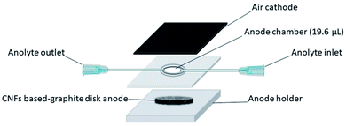
A single-chamber air-cathode microscale MFC with an anode chamber volume of 19.6 μ, was used (Fig. 1). The micro-sized MFC design was inspired by Mink et al. with a modification.39,44 The setup of our MFC was as follows: the 3D disk anode was installed in the silicon rubber (5 mm thick) as the anode holder, while a 1 mm-thick rubber spacer with a central circle hole (5 mm diameter) was used as the anode chamber between the anode and the cathode. The rubber spacer was fixed from one side in the anode holder, while the cathode (0.8 × 0.8 cm2) was glued to the other side. The reactor was operated in fed-batch mode via 0.1 mm syringe tips as the inlet and outlet for inoculation and feeding the anode.2.5. Electrochemical measurements and characterization
Linear sweep voltammetry (LSV) was carried out using a HA-151A potentiostat (HA-151A potentiostat/galvanostat, Japan) to obtain the polarization curves at a scan rate of 1 mV s−1 using a two-electrode setup with the cathode as the working electrode and the anode as both counter and reference electrodes.45,46 The voltage was continuously measured to check the stability, and the data were recorded every 2 min using a GL220 midi-logger. The power (P) was obtained as P = IV and normalized to the anode surface area (19.625 μm). The morphology of the anode was imaged using a field emission scanning electron microscope (FE-SEM, Hitachi US8230). The overall energy losses of the μL-MFC were estimated using the following equation:46| Vdevice = OCV − IRinternal = OCV − I(Ra + Rc + Rm + Re) | (1) |
3. Results and discussion
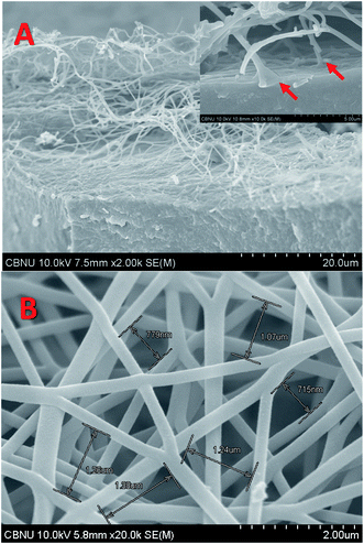
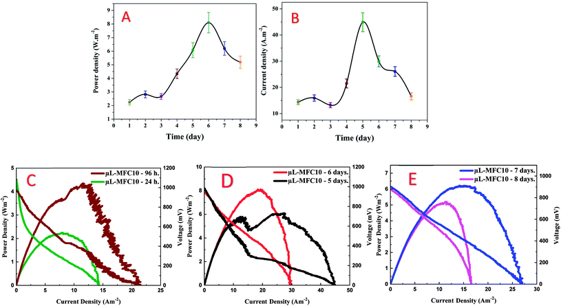
Polyacrylonitrile (PAN) is the most widely used polymer in the fabrication of carbon nanofibers owing to the high graphitization yield and good mechanical properties of the produced products. PAN powder is very fine, so it could be compacted in the form of a disk using a cylindrical mould (1.2 cm inner diameter). The obtained disk was utilized as a collector in the PAN/DMF solution electrospinning. Then, the vacuum-dried PAN disk with the attached electrospun nanofibers was thermally treated (carbonized) at high temperature. Owing to the graphitization process, the size of the disk sharply decreased (as shown in Fig. S2, ESI†). Fig. 2A displays an FE-SEM image of a piece of the produced CNF-attached graphite disk after the calcination process. As shown in the inset, the carbon nanofibers are originated from the disk surface, which indicates the complete merging between the electrospun nanofibers and the disk substrate during the calcination process owing to the similarity of the construction materials (PAN). This built-in formulation reflects an ignored contact resistance between the CNFs and the graphite disk ESI†,47 therefore precluding the contact engineering issues.39 Besides the merit of low interfacial resistance between the CNFs and the substrate disk, the nanofiber skeleton can offer a huge surface area for the microorganisms' attachment due to pregenation possibility of the microorganisms within the nanofibers. Fig. 2B displays an FE-SEM image of the disk surface at a selected high-density area. The conductivity is an important parameter as it strongly affects the electron transfer process through the anode. The conductivity was measured and found to be 4.52 S cm−1, which is consistent with reported CNFs synthesized from a similar polymer (PAN).48The MFC electricity generation could determine the effectiveness of the 3D CNF-based anode in the micro-sized MFC. Compared to the literature, higher maximum power and current densities (8.1 Wm−2 and 44.9 Am−2) were obtained from the proposed 3D CNF-anode-based micro-sized MFC (Fig. 3A–E & Table S1†). A detailed comparison with some reported results can be found in Table S1 in the ESI.† The CNF-based micro-sized MFC prepared using 10 min electrospinning time (μL-MFC10, for short) exhibited rapid startup with considerable generated power (0.83 Wm−2 at 2.98 Am−2) after 30 min of operation (Fig. S3†). This quick startup response qualifies the μL-MFC10 to be a suitable tool for rapid screening of electrode materials and electroactive microbes.16 Furthermore, μL-MFC10 has reasonable sustainability, as it continued to produce valuable power density for more than eight days, indicating good stability and durability of its design and materials.44 The μL-MFC10 power output was almost duplicated within the first 96 h of operation, where the power density increased from 2.24 Wm−2 at 7.89 Am−2 after 24 h to 4.34 Wm−2 at 11.55 Am−2 after 96 h (Fig. 3C). Then the output power steadily increased (almost doubling again) during the 48 h following the first 96 h of operation and achieved the maximum power output (8.1 Wm−2 at 19.34 Am−2) after 6 days of operation, while the maximum current output was achieved after 5 days of running time with 44.9 Am−2 (Fig. 3D). Subsequently, the power production decreased to 6.2 Wm−2 at 14.99 Am−2 with a maximum current density of 26.06 Am−2 at 7 days of operation (Fig. 3E). After 8 days, the μL-MFC10 sustained its power output, achieving 5.19 Wm−2 at 11.27 Am−2, a 1.5 times decrease from the maximum power output (8.1 Wm−2 at 19.34 Am−2) and a 2.3 times increase from the initial power output at 24 h of operation (Fig. 3E).
In the literature, the activity of newly reported anode materials is usually emphasized by comparison of the generated current and power densities with those of previously reported materials. However, it is important to mention that comparison using absolute numbers does not always provide a real evaluation of the results as the actual cell performance depends on many parameters. In continuity of the researchers' strategy, an outline evaluation of the proposed CNF-based anode was performed by comparing the generated power densities with the values reported in the literature. The data shown in Fig. S4 in the ESI† are based on the best of our knowledge from the literature review, and are based on the observed generated power and current densities. It seems the researchers despaired over improving micro-sized MFCs due to the unencouraging generated power; hence not so many reports were introduced. However, as shown, the generated power from our proposed microscale MFC is as high as the reported ones. Therefore, this study might open a new avenue for micro-sized MFCs on research and industry levels. It is worth mentioning that the two reports introduced in 2016 by Ren et al.49,50 represent, based on our best knowledge, the maximum obtained power densities ever reported in the literature: 7720 and 5610 mWm−2. However, the micro-sized MFC proposed in this study could generate higher power density: 8100 mWm−2. Moreover, those two previously reported micro-sized MFCs were based on utilizing ferricyanide solution as the catholyte, while ambient air was exploited to complete the cathodic reaction in the proposed MFC, which adds a significant and important advantage for this cell as it can be easily used. However, it is important to mention that the high generated power and current densities in this study are considered preliminary data; to confidently approve the proposed anode, more experimental and analytical work has to be done in the future.
The impact of the carbon nanofiber packing density and the layer thickness was investigated by preparing three different anode thicknesses by changing the electrospinning time (5, 10 and 20 min) while the other experimental parameters were kept as they were addressed in the literature. The corresponding micro-sized MFCs have been encoded as μL-MFC5, μL-MFC10 and μL-MFC20, respectively. At 48 h of operation, μL-MFC10 produced a power density of 2.82 Wm−2, which is 1.5 and 2 times more than the 5- and 20 min electrospun CNFs (μL-MFC5 and μL-MFC20; 1.91 and 1.38 Wm−2, respectively). In the case of the current production, the μL-MFC10 device produced a current output of 1.4 and 3.5 times more than the μL-MFC5 and μL-MFC20 (11.41 and 4.54 Am−2, respectively) at 48 h of operation (Fig. 4).
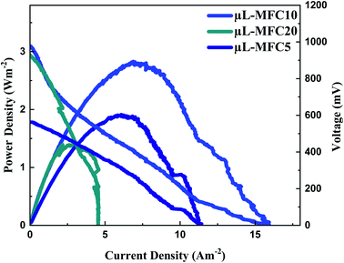 | ||
| Fig. 4 Influence of the electrospinning time on the generated power and current densities. μL-MFC5, μL-MFC10 and μL-MFC20 refer to 5, 10 and 20 min electrospinning time, respectively. | ||
The conductivity of the electrospun CNFs might be improved with increasing the packing density (the numbers of NFs per unit) due to increasing the number of cross-junctions between CNFs per unit volume of the mat.51 However, the packing density passively affects the pores in the CNF network, thereby reducing the area-to-volume ratio, which hinders the microorganisms' penetration throughout the nanofiber matrix. The schematic diagram in Fig. 5 conceptually illustrates the μL-MFC10 outperformance compared to the other formulations. Briefly, at 10 minutes electrospinning time (μL-MFC10), an optimum nanofiber layer packing density and thickness could be achieved, which reflects high conductivity for the electroactive bacteria due to the high area-to-volume ratio, and thus, a higher number of the electroactive bacteria would be penetrating throughout the nanofiber skeleton compared to the relatively longer time for μL-MFC20 (20 min electrospinning time). Moreover, at this optimum time, low mass transfer resistance for the substrate could be obtained. The low performance of μL-MFC5 can be attributed to the lower density of carbon nanofibers (thin layer) than μL-MFC10. Therefore, a smaller amount of electroactive bacterial biofilm could attach and transfer electrons, as can be visualized in the first panel in Fig. 5.
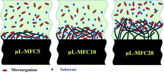 | ||
| Fig. 5 Conceptual illustrations of the influence of the electrospinning time on the CNF layer density and thickness on the surface of the prepared anodes. | ||
Besides the conceptual illustration, the above explanation about the influence of the density of the nanofibers is experimentally proved by FE-SEM images for the cross-section and surface of the used μL-MFC10 (Fig. 6). As shown in Fig. 6A, the surface pores still open after use of the anode. Moreover, as shown in the cross-section image (Fig. 6B), the microorganisms could penetrate the underneath layers and attach to the nanofibers. These results support the fine-grained conceptual illustration in Fig. 5. It is noteworthy that the optimum biofilm thickness and microorganism density could be achieved at the surface of μL-MFC10 anode as optimizing these two parameters distinctly influenced the cell performance.
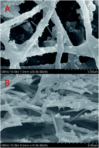 | ||
| Fig. 6 FE-SEM images of the surface (A) and cross-section (B) for the used carbon nanofibers-attached PAN disk anode (μL-MFC10) after using the proposed micro-size MFC. | ||
To study the impact of the nanofiber layer, two identical μL-MFCs were assembled using a bare and CNF-attached (μL-MFC10) sintered PAN disks as anodes. Numerically, the anode disk covered by CNFs exceeded the naked one by 140% for current density and 435% for power density after 3 h of operation time. These results clearly confirm the advantage of CNF attachment, as shown in Fig. S5.†
The possible maximum energy output and the potential causes of energy loss in an MFC can be recognized by determining the specific contributions of the device components to the total internal resistance through energy loss analysis.39 As our reactor is a membrane-less single chamber and the electrolyte resistance is low (approximately 130 Ω), so the membrane and electrolyte resistances are excluded from the components of energy loss, leaving the resistance of the electrode as the main source of energy loss in the system. The energy loss in the μL-MFC10 was 22% (see Materials and methods Section 2.5), which is a good ratio compared to the previously stated micro-size MFC energy loss percentage39 (Fig. S6†). The low energy loss ratio could be attributed to the minimal resistance of the CNF anode and rooting the nanofibers in the disk substrate, which effectively enhance the electron transfer rate. It is noteworthy that cyclic measurements can provide more information for understanding the high performance obtained from the proposed anode. In the future, the observed good performance of the CNF-based anodes will be intensively investigated not only by CV and impedance measurements but also by checking the influence of the kind of microorganism and the nanofiber diameter and packing density.
4. Conclusion
Calcination of a PAN disk covered with a thin layer of electrospun PAN nanofibers leads to the simultaneous graphitization of the electrospun nanofibers and the disk support. The similarity of the construction materials results in a very close shrinkage rate, which protects the nanofibrous morphology from collapsing. Interestingly, the produced carbon nanofibers completely merge with the disk surface and look as though they are planted in the disk, which prevents the creation of interfacial resistance for electron transfer. Utilizing the prepared disk as the anode in a micro-sized MFC enhanced the generated power and current density due to the insertion of the microorganisms throughout the nanofiber matrix, which provides a vast surface area for biofilm formation. However, the packing density and the thickness of the carbon nanofiber coat have to be optimized by adjusting the electrospinning time. To this end, the 10 min electrospun anode was the most suitable for the micro-sized MFC. Although a cheap anode material (carbon) is utilized in a simple air-cathode micro-sized MFC constructed using inexpensive, flexible rubber that relies on ambient oxygen as a terminal electron acceptor, the generated power is high compared to the reported micro-sized microbial fuel cells fabricated from relatively complicated technologies. The detected high generated power and current densities using the proposed anodes encouraged us to perform more studies to properly understand and explain the suggested cell performance.Author contributions
M. Amen did the experimental work and shared in manuscript writing, H. Y. Kim financially supported the manuscript, and N. A. M. Barakat supervised the experimental work, analyzed the results and shared in manuscript writing.Conflicts of interest
The authors have no conflict of interest.References
- M. Gao, P. Wang, L. Jiang, B. Wang, Y. Yao, S. Liu, D. Chu, W. Cheng and Y. Lu, Energy Environ. Sci., 2021, 14, 2114–2157 RSC.
- R. Rossi and B. E. Logan, Chem. Eng. J., 2021, 422, 130150 CrossRef CAS.
- Y. Wang, C. He, W. Li, W. Zong, Z. Li, L. Yuan, G. Wang and Y. Mu, Chem. Eng. J., 2020, 399, 125848 CrossRef CAS.
- M. T. Amen, N. A. Barakat, M. A. H. M. Jamal, S.-T. Hong, I. M. Mohamed and A. Salama, Appl. Energy, 2018, 228, 167–175 CrossRef CAS.
- M. T. Amen, A. S. Yasin, M. I. Hegazy, M. A. H. M. Jamal, S.-T. Hong and N. A. Barakat, R. Soc. Open Sci., 2021, 8, 210996 CrossRef CAS PubMed.
- T. Lin, W. Ding, L. Sun, L. Wang, C.-G. Liu and H. Song, Nano Energy, 2018, 50, 639–648 CrossRef CAS.
- P. Aelterman, M. Versichele, M. Marzorati, N. Boon and W. Verstraete, Bioresour. Technol., 2008, 99, 8895–8902 CrossRef CAS PubMed.
- I. Ieropoulos, J. Winfield and J. Greenman, Bioresour. Technol., 2010, 101, 3520–3525 CrossRef CAS PubMed.
- K.-J. Chae, M.-J. Choi, J.-W. Lee, K.-Y. Kim and I. S. Kim, Bioresour. Technol., 2009, 100, 3518–3525 CrossRef CAS PubMed.
- M. Ghangrekar and V. Shinde, Bioresour. Technol., 2007, 98, 2879–2885 CrossRef CAS PubMed.
- P. Clauwaert, P. Aelterman, L. De Schamphelaire, M. Carballa, K. Rabaey and W. Verstraete, Appl. Microbiol. Biotechnol., 2008, 79, 901–913 CrossRef CAS PubMed.
- V. Debabov, Microbiology, 2008, 77, 123–131 CAS.
- K. Y. Cheng, G. Ho and R. Cord-Ruwisch, Environ. Sci. Technol., 2008, 42, 3828–3834 CrossRef CAS PubMed.
- B. E. Logan, Microbial fuel cells, John Wiley & Sons, 2008 Search PubMed.
- L. Liu and S. Choi, J. Power Sources, 2017, 348, 138–144 CrossRef CAS.
- M. Chiao, J. Microelectromech. Syst., 2008, 17, 1329–1341 Search PubMed.
- M. R. Park, M. K. Banks, B. Applegate and T. J. Webster, Int. J. Nanomed., 2008, 3, 497 CAS.
- Y. Fan, H. Hu and H. Liu, J. Power Sources, 2007, 171, 348–354 CrossRef CAS.
- P. Parkhey and R. Sahu, Int. J. Hydrogen Energy, 2021, 46, 3105–3123 CrossRef CAS.
- H. Sakai, T. Nakagawa, Y. Tokita, T. Hatazawa, T. Ikeda, S. Tsujimura and K. Kano, Energy Environ. Sci., 2009, 2, 133–138 RSC.
- B. Bian, D. Shi, X. Cai, M. Hu, Q. Guo, C. Zhang, Q. Wang, A. X. Sun and J. Yang, Nano Energy, 2018, 44, 174–180 CrossRef CAS.
- H. Ren, S. Pyo, J. I. Lee, T. J. Park, F. S. Gittleson, F. C. C. Leung, J. Kim, A. D. Taylor, H. S. Lee and J. Chae, J. Power Sources, 2015, 273, 823–830 CrossRef CAS.
- Y. Z. Fan, H. Q. Hu and H. Liu, J. Power Sources, 2007, 171, 348–354 CrossRef CAS.
- B. Min and B. E. Logan, Environ. Sci. Technol., 2004, 38, 5809–5814 CrossRef CAS PubMed.
- S. K. Chaudhuri and D. R. Lovley, Nat. Biotechnol., 2003, 21, 1229–1232 CrossRef CAS PubMed.
- Z. He, S. D. Minteer and L. T. Angenent, Environ. Sci. Technol., 2005, 39, 5262–5267 CrossRef CAS.
- H. Richter, K. McCarthy, K. P. Nevin, J. P. Johnson, V. M. Rotello and D. R. Lovley, Langmuir, 2008, 24, 4376–4379 CrossRef CAS.
- M. Rosenbaum, F. Zhao, U. Schroder and F. Scholz, Angew. Chem., Int. Ed. Engl., 2006, 45, 6658–6661 CrossRef CAS PubMed.
- C. E. Zhao, P. Gai, R. Song, Y. Chen, J. Zhang and J. J. Zhu, Chem. Soc. Rev., 2017, 46, 1545–1564 RSC.
- Y. C. Yong, X. C. Dong, M. B. Chan-Park, H. Song and P. Chen, ACS Nano, 2012, 6, 2394–2400 CrossRef CAS.
- U. Karra, S. S. Manickam, J. R. McCutcheon, N. Patel and B. Li, Int. J. Hydrogen Energy, 2013, 38, 1588–1597 CrossRef CAS.
- N. A. Barakat, M. A. Yassin, A. S. Yasin and S. Al-Meer, Int. J. Hydrogen Energy, 2017, 42, 21741–21750 CrossRef CAS.
- N. A. Barakat, M. A. Yassin, F. S. Al-Mubaddel and M. T. Amen, Appl. Catal., A, 2018, 555, 148–154 CrossRef CAS.
- N. A. Barakat, K. A. Khalil, I. H. Mahmoud, M. A. Kanjwal, F. A. Sheikh and H. Y. Kim, J. Phys. Chem. C, 2010, 114, 15589–15593 CrossRef CAS.
- C. Kim, K. S. Yang, M. Kojima, K. Yoshida, Y. J. Kim, Y. A. Kim and M. Endo, Adv. Funct. Mater., 2006, 16, 2393–2397 CrossRef CAS.
- M. Ghasemi, S. Shahgaldi, M. Ismail, Z. Yaakob and W. R. W. Daud, Chem. Eng. J., 2012, 184, 82–89 CrossRef CAS.
- S. Chen, G. He, A. A. Carmona-Martinez, S. Agarwal, A. Greiner, H. Hou and U. Schröder, Electrochem. Commun., 2011, 13, 1026–1029 CrossRef CAS.
- S. L. Chen, H. Q. Hou, F. Harnisch, S. A. Patil, A. A. Carmona-Martinez, S. Agarwal, Y. Y. Zhang, S. Sinha-Ray, A. L. Yarin, A. Greiner and U. Schroder, Energy Environ. Sci., 2011, 4, 1417–1421 RSC.
- J. E. Mink, R. M. Qaisi, B. E. Logan and M. M. Hussain, NPG Asia Mater., 2014, 6, e89 CrossRef CAS.
- S. Shahgaldi, M. Ghasemi, W. R. W. Daud, Z. Yaakob, M. Sedighi, J. Alam and A. F. Ismail, Fuel Process. Technol., 2014, 124, 290–295 CrossRef CAS.
- F. Zhao, R. C. Slade and J. R. Varcoe, Chem. Soc. Rev., 2009, 38, 1926–1939 RSC.
- M. C. Hatzell, R. D. Cusick and B. E. Logan, Energy Environ. Sci., 2014, 7, 1159–1165 RSC.
- Y.-J. Jeon, P.-J. Park and S.-K. Kim, Carbohydr. Polym., 2001, 44, 71–76 CrossRef CAS.
- J. E. Mink and M. M. Hussain, ACS Nano, 2013, 7, 6921–6927 CrossRef CAS PubMed.
- G.-L. Zang, G.-P. Sheng, C. Shi, Y.-K. Wang, W.-W. Li and H.-Q. Yu, Energy Environ. Sci., 2014, 7, 3033–3039 RSC.
- B. E. Logan, B. Hamelers, R. Rozendal, U. Schroder, J. Keller, S. Freguia, P. Aelterman, W. Verstraete and K. Rabaey, Environ. Sci. Technol., 2006, 40, 5181–5192 CrossRef CAS PubMed.
- M. Li, S. Zhao, G. Han and B. Yang, J. Power Sources, 2009, 191, 351–356 CrossRef CAS.
- J. S. Im, S. J. Kim, P. H. Kang and Y.-S. Lee, J. Ind. Eng. Chem., 2009, 15, 699–702 CrossRef CAS.
- H. Ren, H. Tian, C. L. Gardner, T.-L. Ren and J. Chae, Nanoscale, 2016, 8, 3539–3547 RSC.
- H. Ren, S. Rangaswami, H.-S. Lee and J. Chae, J. Micromech. Microeng., 2016, 26, 095016 CrossRef.
- P. S. Kumar, J. Sundaramurthy, S. Sundarrajan, V. J. Babu, G. Singh, S. I. Allakhverdiev and S. Ramakrishna, Energy Environ. Sci., 2014, 7, 3192–3222 RSC.
Footnotes |
| † Electronic supplementary information (ESI) available: More experimental data and comparison of the μL-MFC performance in this work and recently reported studies. See https://doi.org/10.1039/d2ra00591c |
| ‡ These authors have similar contributions. |
| This journal is © The Royal Society of Chemistry 2022 |

