 Open Access Article
Stabilization of lithium anode with ceramic-rich interlayer for all solid-state batteries†
Nicolas Delaporte *,
Gilles Lajoie,
Ali Darwiche
 ,
Marie-Josée Vigeant,
Steve Collin-Martin and
Daniel Clément
Center of Excellence in Transportation, Electrification and Energy Storage, 1806 Bd. Lionel-Boulet, Varennes, QC, Canada. E-mail: Delaporte.Nicolas@hydro.qc.ca
First published on 24th May 2022
Abstract
The deposition of thin layers of polymer/ceramic on a lithium surface to produce a strong barrier against dendrites was demonstrated. Different forms (needle, sphere, rod) and types of ceramic (Al2O3, Mg2B2O5) were tested and polymer/ceramic interlayers of a few micrometers (4 μm minimum) between the lithium and the PEO-based solid polymer electrolyte (SPE) were deposited. Interlayers with high amounts of ceramic up to 85 wt% were successfully coated on the surface of lithium foil. Compact “polymer in ceramic” layers were observed when Al2O3 spheres were used for instance, providing a strong barrier against the progression of dendrites as well as a buffer layer to alleviate the lithium deformation during stripping/plating cycles. The electrochemical performance of the lithium anodes was assessed in symmetrical Li/SPE/Li cells and in full all-solid-state LiFePO4 (LFP)/SPE/Li batteries. It was observed for all the cells that the charge transfer resistance was significantly reduced after the deposition of the polymer/ceramic layers on the lithium surface. In addition, the symmetrical cells were able to cycle at higher C-rates and the durability at C/4 was even improved by a factor of 8. Microscopic observations of Li/SPE/Li stacks after cycling revealed that the polymer/ceramic interlayer reduces the deformation of lithium upon cycling and avoids the formation of dendrites. Finally, LFP/SPE/Li batteries were cycled and better coulombic efficiencies as well as capacity retentions were obtained with the modified lithium electrodes. This work is patent-pending (WO2021/159209A1).
1 Introduction
The change of paradigm of this 21st century, caused by the depletion of fossil fuels, global warming and the frenetic pollution generated by human activity, raises awareness and forces us to change our habits. Combined with the widespread use of portable technologies such as laptops and cells, the development of sustainable energy storage systems has become one of the priorities of our society.1 Nowadays, lithium-ion batteries (LIBs) still dominate the rechargeable battery market in the portable electronic devices and electric vehicles sector because of their high energy density and long-life.2 To convince governments to accept the transition toward transportation electrification, affordable, safe and long-range electric cars are needed.3 In contrast to LIBs, all solid-state batteries (ASSB) are safer due to the lack of flammable organic components and also offer the potential for a dramatic improvement of energy density.4 In fact, the use of a solid electrolyte, which acts as electrical insulator, ionic conductor and physical barrier for lithium dendrites, enables the use of lithium metal as the anode material.5 Lithium metal is characterized by a very high theoretical specific capacity (3860 mA h g−1) as well as a low redox potential (−3.04 V vs. SHE).6 Therefore, Li metal is paving the way for high energy density batteries that could accelerate the deployment of long-range electric vehicles.7 Thus, an increase in volumetric energy density of up to 70% can be expected in comparison to LIBs still using conventional anode materials.8Unfortunately, lithium metal suffers from large volume changes during cycling with the formation of dendrites and “dead Li” that could led to internal short-circuit.9 In addition, some interfacial problems remain unresolved in ASSB,10 such as the poor adhesion at the Li-electrolyte interface11,12 and the high reactivity of lithium with some ceramic electrolytes (e.g., LAGP).13 Moreover, even if in ASSB, the solid electrolyte represents a strong barrier to slow down the progression of dendrites, in most the cases, the Young's modulus of polymer electrolyte is under the threshold value of 6 GPa to suppress the growing of Li dendrites.14,15 All these interfacial and physical problems motivated research groups to actively found solutions to democratize the use of lithium metal anode. The most widely employed method is to use a composite polymer electrolyte (CPE) that is a mixture of a polymer with a ceramic. Firstly, it is generally reported than the incorporation of ceramics in the polymer matrix induces an increase of the ionic conductivity caused by the reduction of crystallinity and glass transition temperature.16 In addition, the adding of ceramics improves the mechanical properties and the interfacial stability of the polymer electrolyte.17 Finally, well-dispersed fillers slow down lithium dendrites progression. Several examples of inert ceramics have been reported such as TiO2,18 SiO2,19 Al2O3,20 Mg2B2O5,21 ZrO2 (ref. 22) but ionically conductive ceramics can be also used such as Li6.75La3Zr1.75Ta0.25O12 (LLZTO),23 Li0.33La0.557TiO3 (LLTO),24 Li1.3Al0.3Ti1.7(PO4)3 (LATP),25 Li1.5Al0.5Ge1.5(PO4)3 (LAGP),26 Li7La3Zr1.75Nb0.25O12 (LLZN)27 or even the sulfide-type Li10GeP2S12 ceramic.28 However, in most the cases, a high quantity of ceramic is needed to impede the progression of dendrites and the mechanical properties can be adversely affected. Moreover, the self-standing CPE is less sticky and the contact with the electrodes is less efficient leading to high charge-transfer resistance and bad electrochemical performance, especially at high C-rates.29
To permit a protection against dendrites without affecting the performance and the handling of the solid polymer electrolyte (SPE), a strategy consisted to protect the surface of lithium with an interlayer of polymer and ceramic.11 Several example have been recently reported such as the deposition on lithium surface via doctor blade casting of a mixture of nanometric spherical Cu3N particles and styrene butadiene rubber copolymer (SBR).30 The most used ceramic is Al2O3 because it is a cheap and abundant material that can be synthesized in numerous forms. For instance, Lee et al. reported that the cycle life of Li–oxygen batteries was enhanced after the deposition of a 20 μm thick layer on lithium composed of micrometric Al2O3 particles and polyvinylidene fluoride (PVDF)–hexafluoro propylene.31 Similarly, Gao and coworkers prepared a mixture of 100 nm Al2O3 spheres with PVDF as a binder in DMF solvent, which was spread by spin-coating on a lithium foil.32 The performance of their Li–S battery using the modified lithium were strongly improved with the surface of the lithium remaining smooth even after several charge/discharge cycles. A porous polyimide layer with 10 nm Al2O3 filler was proposed by Peng et al. to provide inter-spaces to confine lithium growth.33
In this work, we report the deposition by simple doctor blading method of thin layers of polymer/ceramic on lithium surface to generate a strong barrier against dendrites. Several forms (rod, sphere and needle) and types of ceramic (Mg2B2O5 and Al2O3) were tested and high ceramic amounts of up to 85 wt% were used to form the polymer/ceramic interlayers between the lithium and the SPE. Thin layers with a minimum thickness of ∼4 μm are well fixed on the surface of the lithium and closely compacted when Al2O3 spheres were used for instance, providing a kind of “polymer in ceramic” interlayer. The electrochemical performance of the lithium anodes were assessed in symmetrical Li/SPE/Li cells and in full all-solid-state LiFePO4 (LFP)/SPE/Li batteries. It was observed for all the cells that the charge transfer resistance was significantly reduced after the deposition of the polymer/ceramic layers on lithium surface. In addition, the symmetrical cells were able to cycle at higher C-rates and the durability at C/4 was even improved by a factor of 8. Microscopic observations of Li/SPE/Li stacks after cycling revealed that the polymer/ceramic interlayer reduces the deformation of lithium upon cycling and avoids the formation of dendrites. Finally, LFP/SPE/Li batteries were cycled and better coulombic efficiencies as well as capacity retentions were obtained with the modified lithium electrodes. This work is patent-pending (WO2021/159209A1).
2 Experimental section
2.1 Synthesis of Mg2B2O5 ceramic
Mg2B2O5 ceramic is already used in the composition of solid electrolytes for all-solid-state batteries.21 Its synthesis is based on a recent study.34 Approximately 20.33 g of MgCl2·6H2O (Sigma-Aldrich) and 7.57 g of NaBH4 (Sigma-Aldrich) are ball milled in a Teflon container containing 200 g of zirconium beads. In total, 120 h of mixing were performed at 300 rpm, making successively 120 cycles of 60 min mixing time and 30 min break. After this step, the powder was collected and placed in a tubular oven to be calcined under air with a ramp of 2 °C min−1 from 20 to 800 °C. The temperature was maintained at 800 °C for 2 h and the powder was recovered after cooling. The last step consisted to wash intensively the powder with deionized water to remove NaCl. The resulting material was dried in an oven at 120 °C under vacuum.2.2 Preparation of ceramics suspension
![[thin space (1/6-em)]](https://www.rsc.org/images/entities/char_2009.gif) 000) was dispersed in a small amount of anhydrous tetrahydrofuran (THF from Sigma-Aldrich) that was mixed until a viscous solution was obtained. Lithium bis(trifluoromethanesulfonyl)imide salt (LiTFSI from Sigma-Aldrich) corresponding to a O
000) was dispersed in a small amount of anhydrous tetrahydrofuran (THF from Sigma-Aldrich) that was mixed until a viscous solution was obtained. Lithium bis(trifluoromethanesulfonyl)imide salt (LiTFSI from Sigma-Aldrich) corresponding to a O![[thin space (1/6-em)]](https://www.rsc.org/images/entities/char_2009.gif) :
:![[thin space (1/6-em)]](https://www.rsc.org/images/entities/char_2009.gif) Li molar ratio of 20
Li molar ratio of 20![[thin space (1/6-em)]](https://www.rsc.org/images/entities/char_2009.gif) :
:![[thin space (1/6-em)]](https://www.rsc.org/images/entities/char_2009.gif) 1 was then added to the polymer solution. After mixing for several hours, the polymer solution was diluted with THF to obtain 26.8 wt% of solid (polymer and salt).
1 was then added to the polymer solution. After mixing for several hours, the polymer solution was diluted with THF to obtain 26.8 wt% of solid (polymer and salt).2.3 Polymer casting on lithium foil
Several lithium foils were tested and consisting in pure lithium (simply abbreviated in Li), an LiAl alloy (named LiAl) and a LiMg alloy (named LiMg). Pieces of lithium foil of 18 cm × 4.5 cm were cut in a dry room. Then, the different solutions were casted on the lithium surface using doctor blade technique. The wet thickness is adjusted depending on the dry thickness desired after drying. Thin dry overcoatings below 7 μm and thick overcoatings superior to 15 μm were deposited on lithium surface. The lithium foil was let drying in a ventilated hood for 5 minutes and placed in a Büchner glass assembly, which was put under continuous vacuum for 2 minutes. The different overcoatings are simply named X% Mg2B2O5, X% Al2O3-sph and X% Al2O3-ndl when X% of Mg2B2O5, Al2O3-sph and Al2O3-ndl ceramics are used, respectively, in the composition of the ceramic/polymer solutions. For instance, the LiMg alloy modified with the ceramic/polymer solution made with 85 wt% of Al2O3-sph is identified as follow: LiMg + 85% Al2O3-sph.2.4 Preparation of self-standing solid polymer electrolyte
PEO polymer with LiTFSI salt was used as SPE. The thickness of the self-standing SPE is about 25 μm.Additionally, 25 μm thick 70% Al2O3-sph, 85% Al2O3-sph and 50% Al2O3-ndl SPEs made with the freshly prepared ceramic/polymer solutions were casted on polypropylene film to be tested as self-standing ceramic-rich SPEs.
2.5 Preparation of LFP electrodes
Nanometric potato shape carbon-coated LFP powder (75.3 wt%), carbon black (1 wt%), LiTFSI salt (6.27 wt%) and a PEO (19.23 wt%) were mixed together using proper amount of an acetonitrile/toluene (80![[thin space (1/6-em)]](https://www.rsc.org/images/entities/char_2009.gif) :
:![[thin space (1/6-em)]](https://www.rsc.org/images/entities/char_2009.gif) 20 v/v) solvent mixture. The slurry was cast on a carbon-coated aluminum foil (15 μm) to have an active mass loading of 8 mg cm−2 and a thickness of ∼35 μm after drying. The process was conducted inside a dry room with a dew point less than −50 °C. The electrodes were conserved in a metal plastic bag in dry atmosphere before being utilized.
20 v/v) solvent mixture. The slurry was cast on a carbon-coated aluminum foil (15 μm) to have an active mass loading of 8 mg cm−2 and a thickness of ∼35 μm after drying. The process was conducted inside a dry room with a dew point less than −50 °C. The electrodes were conserved in a metal plastic bag in dry atmosphere before being utilized.
2.6 Cell assembling
2.7 LFP/SPE/Li batteries
A SPE film was placed between the LFP electrode (16 mm diameter) and a pristine or modified lithium electrode. The whole is laminated at 80 °C in a dry room as for symmetric Li/Li cells and the assembling in coin cells is performed in an Ar-filled glove box.2.8 Electrochemical testing
All the coin cells were electrochemically characterized with a BioLogic VMP3 potentiostat.Electrochemical impedance spectroscopy measurements of the cells were performed with an AC amplitude of 10 mV and a frequency range of 200 kHz to 10 mHz. The Nyquist plot was recorded at OCV before stripping-plating experiment and after stabilization of the temperature at 50 °C. Additional measures were recorded after stripping-plating cycling at different C-rates and every three cycles at 1C rate.
Galvanostatic stripping-plating cycling of the symmetric cells was recorded with different current densities corresponding to C-rates of C/24, C/12, C/6, C/3, C/2 and 1C. Two cycles at C/24 and three cycles for C-rates ranging from C/12 to C/2 were performed, and the cycling at 1C was let to run until short-circuit happened. The areal capacity was set to 1.287 mA h cm−2 (1C = 1.287 mA cm−2), which corresponds to the capacity of a cathode with an active mass loading of ∼8 mg cm−2.
Long term stability experiments were performed at C/4 after two cycles at C/24.
2.9 Characterization
X-ray diffraction (XRD) analysis of Mg2B2O5 powder was performed using a SmartLab X-ray diffractometer (Rigaku) with Co Kα1 radiation (λ1 = 1.78892 Å). Data were collected between 10° and 100°, with a step size of 0.02° and a scan speed of 3.04° min−1, using a D/tex Ultra 250 detector.Thin and thick polymer/ceramic overcoatings on lithium surface were observed with a FlexSEM 1000 Scanning Electron Microscope (SEM, from Hitachi High-Technologies Corporation) placed in a dry room. Prior to the analysis, samples were dried at 80 °C under vacuum for several hours. Secondary electron (SE) images were obtained at an accelerating voltage of 5 kV and a working distance of about 5–6 mm.
Cross-section views of LiAl/SPE/LiAl stacking extracted from coin cells after cycling under different conditions were observed using scanning electron microscope Lyra 3 by TESCAN. Samples were prepared in a dry chamber and inserted in the SEM using an air-tight transfer holder to minimize external contamination. The micrograph and X-ray map were acquired at an accelerating voltage of 5 kV, a probe current of 500 pA and a working distance of 9 mm.
3 Results and discussion
3.1 Deposition of ceramics on lithium surface
Many studies focused on the Al2O3 deposition on Li surface via sputtering36 or atomic layer deposition (ALD)37–39 methods. Although these methods are simple and provide dense ceramic layers, the mains drawbacks of these methods are the duration of the deposition process and the difficulty to scale. In contrary, web coating or doctor blade coating methods are widely used in Li-ion batteries manufacturing industries, but a polymer is required to fix the ceramic to the substrate to coat. When the percentage of ceramic is low (for instance <10 wt% as usually reported in the literature), the composite ink casting is easy and even self-standing CPE can be easily obtained.40,41 However, to have a durable protection against dendrites, the layer must contain the highest ceramic quantity as possible. As the ceramic percentage increases inside the ceramic-polymer layer, the cohesion of the CPE is not enough, and the ink must be applied directly on the substrate (e.g. lithium surface). Several other aspects such as the fragility, the sticking problems, and the low Li ion conductivity for the Li foils with thick ceramic overcoatings will be presented and discussed below and in the ESI.†As described in the Experimental section, lithium with thin (<7 μm) and thick (>15 μm) overcoatings of polymer/ceramic with different types (spherical, Al2O3-sph and needle-like Al2O3, Al2O3-ndl) and concentrations of ceramics were prepared and studied in symmetric coin-cells and in LFP/SPE/Li batteries. Thin overcoatings are used with a self-standing SPE and act as an interlayer to protect lithium from dendrites progression. The deposition of thick overcoatings on lithium permits to remove the self-standing SPE during the cell assembly and to compare the performances between a thin and a thick layer of polymer/ceramic.
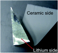
Fig. 1 shows a photograph of an 85% Al2O3-sph overcoating on the surface of a lithium foil. On the reverse side, the shiny lithium surface is well visible while the coated side presents a uniform white surface composed of a ceramic layer of ∼4–5 μm. The integrity of the ceramic layer is kept even if the lithium foil is bent or cut with scissors. However, using more than 85 wt% of this kind of ceramic (spherical particles) led to a loss of mechanical strength. Using less ceramic is less sufficient against dendrite progression and then the optimal quantity for this ceramic was fixed to 85 wt%.
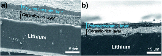
Fig. 2 shows SEM images of an 85% Al2O3-sph overcoating on the surface of lithium. The thickness is about 6–7 μm. It is clearly seen that two layers are present. The one that is deposited face to the lithium is mainly composed of ceramics (i.e., ceramic-rich layer). On the top, a polymer/ceramic-rich layer is obtained with a higher concentration in polymer to favor the cohesion of the film at its surface and to stick a minimum with the solid polymer electrolyte. The film seems dense and mainly composed of small spherical Al2O3 particles (see top view of surface) while the polymer is hardly discernible at this magnification. The surface is not completely uniform but enough flat to obtain a good contact with the SPE.
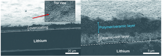 | ||
| Fig. 2 SEM images showing an overcoating of 85% Al2O3-sph (∼6–7 μm) on the surface of LiAl. Two layers are well distinguishable: a polymer/ceramic and a ceramic-rich layers. | ||
Fig. 3 shows (a) a SEM image and (b, c) the corresponding elemental mapping in Al, O and C for a lithium foil (LiAl) with an overcoating of 50% Al2O3-ndl (∼6–7 μm). This Al2O3 powder with a needle-like morphology possesses a higher specific surface area in comparison to the spherical Al2O3 (Al2O3-sph) and consume more polymer. Thus, the maximum concentration of Al2O3-ndl in the film is fixed to 50%. Above this limit, the film starts to crumble if pressure is applied on. The surface looks more like a ceramic than a mix of polymer and ceramic. In comparison to the relatively flat surface of the lithium observed in Fig. 2, the 50% Al2O3-ndl coating appeared more porous and composed of agglomerates of ceramic. The elemental mapping (Fig. 3b and c) shows a high concentration of aluminum and a weak signal for the carbon that corresponds to the presence of the polymer.
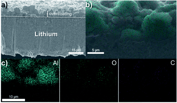 | ||
| Fig. 3 (a) SEM image and (b, c) the corresponding elemental mapping in Al (blue), O (green) and C (purple) of a LiAl with an overcoating of 50% Al2O3-ndl (∼6–7 μm). | ||
Fig. 4 shows SEM images of thick overcoatings deposited on LiAl surface and composed of (a) 70% Al2O3-sph (∼15–20 μm) and (b) 85% Al2O3-sph (∼15 μm). As observed for thin overcoatings, the thickness for the thick films is relatively uniform without huge agglomerates. The separation between the polymer/ceramic (dark) and the ceramic-rich layers (bright) is well observable. The difference in the Fig. 4b is more visible due to the high concentration of ceramic (85%) in the composition of the slurry. These lithium electrodes were assembled in coin-cells without the adding of SPE and the electrochemical results will be discussed below.
Additional films made with the Mg2B2O5 ceramic are presented in the ESI.† The material was successfully prepared through a simple mechanosynthesis followed by a thermal treatment under air and a washing step with deionized water. The detailed protocol is given in the Experimental section. Fig. S1† presents the XRD pattern and a SEM image of the Mg2B2O5 powder. Only one pure crystalline phase was detected by XRD (JCPDS 04-009-3360) and the ceramic was composed of tough nanometric and micrometric rods. Fig. S2† shows SEM cross-section and top views of an overcoating of 70% Mg2B2O5 (∼6 μm) on the surface of a LiAl electrode. The thickness is relatively uniform but at the surface some porosity is easily visible due to the long ceramic rods used.
3.2 Cycling of symmetric Li/Li cells with pristine lithium foils
The electrochemical performance of the pristine LiAl foil without overcoating were firstly assessed in symmetric cell. Fig. 5 shows cross-section views of the LiAl/SPE/LiAl stack used to make coin-cells. The interfaces between the lithium foils and the SPE seems very good with no air bubbles trapped during the hot-pressing process. The corresponding elemental mapping confirmed the proper contact between the electrodes and the electrolyte. The sulfur and the fluorine come from the lithium salt used in the SPE.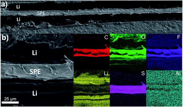 | ||
| Fig. 5 (a and b) SEM cross-section views of a LiAl/SPE/LiAl stack with (b) the corresponding elemental mapping in C (red), O (green), F (purple), Li (yellow), S (pink) and Al (blue). | ||
The Fig. 6 presents (a) the Nyquist plots as well as (b) the long-term stability experiment at a C/4 rate and (c) the rate capability for two symmetric Li/Li cells. The Nyquist plots shown in Fig. 6a were recorded at OCV before stripping-plating experiment. At the very high frequencies, the electrolyte resistance on the horizontal axis is about 6–7 Ω for the two cells. This resistance is that of the self-standing SPE film. A semi-circle in the medium–high frequencies is observed and attributed to the charge transfer resistance (RCT). The impedance profiles are similar for the two cells and the RCT is about 94 Ω. The Fig. 6b show the long-term stability experiment at a C/4 rate for one of the coin cells. The two cycles at C/24 show the square shape of an excellent stripping/plating of lithium with a low polarization. At C/4, the overvoltage increases after each cycle and after the seventh cycle the stripping/plating process starts to be disturbed due to interface destruction between Li metal and the electrolyte. Finally, after about 95 h of cycling at C/4, the cell died due to a short circuit. Then, the second symmetric cell was cycled at different cycling rates up to 1C. The Fig. 6c shows the corresponding rate capability. At a low C-rate of C/12, the polarization slightly increased at each cycle and the cell was not able to cycle at C/6 or roughly.
Additional coin-cells assembled with the pristine LiMg and Li (without aluminum) foils were electrochemically tested. The same cycling tests were realized, and the results are presented in Fig. S3† for the LiMg anode and Fig. S4† for the pure Li foil. LiMg and LiAl gave similar results in term of overvoltage and durability at C/4. The cell with the LiMg electrode completed the three cycles at C/6 but failed to cycle at C/3. For the coin-cells made with the pure Li electrode (without Al doping), the charge transfer resistance was much higher, about 3 times in comparison to the cells with the LiAl foil. In consequent, the cell presented a cycling at C/4 with an important overvoltage on the first cycles, rapidly followed by an erratic cycling demonstrating the poor interfacial stability of this lithium.
3.3 Cycling of symmetric Li/Li cells with modified lithium foils with spherical Al2O3 ceramic
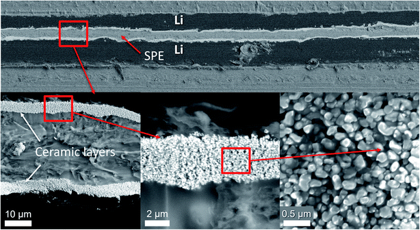
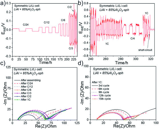
Symmetric cells assembled with two LiAl electrodes modified with a ∼4 μm thick 85% Al2O3-sph ceramic layer were cycled with the same protocols than for the reference cells of Fig. 6. The Fig. 7 presents cross-section views of a LiAl/SPE/LiAl stack with a ∼4 μm thick 85% Al2O3-sph ceramic layer on the surface of the lithium foils. Even if the surface of the lithium with the thin layer of ceramic is not very sticky, after hot pressing, a relatively good contact between the lithium electrodes and the SPE was obtained, as put in evidence in Fig. 7. The SEM images show the compact ceramic layer that acts as a buffer layer to accommodate the lithium expansion during cycling and reduces the progression of dendrites. The interlayer is very dense in ceramic and the polymer is visible at the surface of each particle of Al2O3-sph ceramic providing a pathway for lithium-ion conduction. The fabrication process results in a “polymer in ceramic” interlayer that is easily transposable to the industrial scale and tunable depending on the desired properties (flexibility, conductivity, thickness, adherence…).The electrochemical performance for a symmetric LiAl/SPE/LiAl cell assembled with the same stack of Fig. 7 are shown in Fig. 8. The rate capability up to a C/2 rate is presented in Fig. 8a and the rapid cycling at 1C in Fig. 8b. It is worth noting that the cycling was quite stable up to C/6 with a perfect square shape and a low overvoltage of ±60 mV revealing a stable stripping/plating process. The improvement in comparison to the reference cell without any modification of the lithium is impressive since the cell was not able to cycle correctly at C/6. At a C/3 rate, the overvoltage starts to increase to ±150 mV and the voltage presents some oscillations during the stripping/plating of lithium that is attributable to the deformation of the lithium/SPE interface. This phenomenon will be demonstrated below with the cycling and post-mortem SEM observations of an asymmetric Li/Li cell. Fig. 8b shows that the cell was able to cycle at 1C even if a high overvoltage was obtained, which is mainly due to the low ionic conductivity of the SPE at 50 °C. After 318 h of cycling, the cell short-circuited suddenly due to the repeated cycling at 1C favorizing the formation of dendrites. The Fig. S5† shows a SEM cross-section view with the corresponding elemental mapping for the LiAl/SPE/LiAl stack after the short-circuit occurred. Evident traces of dendrites growth are visible with the presence of dead lithium in the SPE and the destruction of the ceramic layer in some places. The Fig. 8c presents the impedance spectra after assembling the cell and after cycling at different C-rates ranging from C/24 to 1C. During the first cycles, the evolution of the impedance shows a slight increase of the RCT from 32 Ω after assembling to about 54 Ω after stabilization at a C/2 rate. Then, every three cycles at 1C, an impedance measurement was performed to determinate if the cell is still running good or not. The impedance spectra are presented in Fig. 8d. The RCT varies from 54 to 50 Ω between the third and the sixth cycle at 1C and drops to 40 Ω for the rest of the cycling. This observation is consistent with the galvanostatic cycling presented in Fig. 8b. In fact, on the first cycles at 1C the overvoltage was about ±0.5 V, typical of a resistance to the motion of lithium ions, then, on the subsequent cycles the overvoltage decreases to 0.2–0.3 V. This behavior is also observed but less pronounced for a symmetric coin-cell made with lithium foils covered with the needle-like Al2O3 ceramic (see Fig. 9). This is simply due to the progressive stabilization of the cycling after the imposition of an important constant current.
Finally, the same improvement of cyclability was observed for pure Li electrodes (no Al doping) covered with the 85% Al2O3-sph ceramic layer (Fig. S6†) and the cell was able to cycle at C/4 for 250 h before a short-circuit appeared (Fig. S6b†). A second cell cycled very well at different C-rates and for about 110 h at 1C before failure (Fig. S6d†). For the cells assembled with the LiMg electrodes containing an 85% Al2O3-sph ceramic layer (see Fig. S7† for electrochemical results), the improvement was not such evident but the cycling life at C/4 was effectively improved. In contrast, the critical current did not exceed C/3 and the limitation seems due to the LiMg alloy itself. Further investigations will be planned to confirm this behavior.
3.4 Cycling of asymmetric Li/Li cells with modified lithium foils with needle-like Al2O3 ceramic
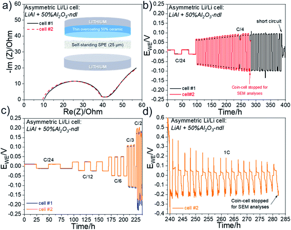
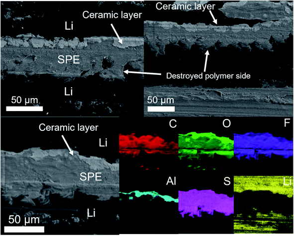
The beneficial effect of incorporating ceramics in an interlayer has been clearly demonstrated with the spherical Al2O3. Additional tests were performed with the needle-like Al2O3 ceramic (Al2O3-ndl). Although the ceramic layer seems less compact and uniform (see SEM image of Fig. 3) than that obtained with the spherical alumina (Fig. 7), the electrochemical results are more interesting. Firstly, to prove that the “anarchic” current observed at high current, especially at 1C, is related to the deformation of the electrolyte–electrode interface, asymmetric Li/Li cells were assembled with a pristine LiAl electrode and a LiAl electrode modified with a ∼5 μm thick 50% Al2O3-ndl ceramic layer. The schematic representation of the cell assembly is shown in Fig. 9a in inset. The Nyquist plots depicted in Fig. 9a for two cells show similar electrolyte and charge transfer resistances, which demonstrate the good reproducibility of the cell assembling. In addition, the RCT of ∼30 Ω after assembling is the same that obtained for the cell assembled with the lithium electrodes containing the 4 μm thick 85% Al2O3-sph ceramic layer (Fig. 8c). The two cells were then cycled for hundreds of hours at a C/4 rate. The corresponding galvanostatic cyclings are represented in Fig. 9b. There is a perfect match between the two cells that present a stable stripping/plating of lithium with a low overvoltage inferior to 0.1 V. The stability has been greatly improved in comparison to the reference cell without modification of lithium and cycled under the same conditions. In fact, this cell died after only 190 h of cycling at C/4 and presented a rapid increase of resistance at each cycle. In contrast, the adding of the ceramic layer on the surface of the working electrode doubled the lifespan since a short-circuit suddenly appeared after 380 h of cycling. The second cell was stopped before a short-circuit appeared and the stack was observed by SEM. The Fig. 10 shows the cross-section view and the corresponding elemental mapping of this stack after cycling. After hundreds of hours of cycling, the interfaces between the SPE and both the pristine and the modified lithium foils remained intact with no evidence of dead lithium or important deformation of the SPE. This observation was expected since the voltage remained quite stable during the stripping/plating process. Two other coin-cells were assembled and cycled at different C-rates. The corresponding cycling data for these two cells are represented in Fig. 9c and they still show an incredible reproducibility. The overvoltage is even lower at C/3 than that obtained for the cell assembled with lithium containing the 4 μm thick 85% Al2O3-sph ceramic layer (see Fig. 8a), which also started to present some oscillations during the stripping/plating of lithium. At a C/2 rate, the asymmetric behavior is slightly visible with more voltage oscillations during the plating process that means one of the two lithium electrodes is more deformed than the other. Finally, at 1C, the asymmetric behavior is clearly present as put in evidence in the Fig. 9d. During the charge, the voltage seems to stabilize while the reduction process appeared very perturbed with no stable voltage assuming the destruction of the unmodified lithium/SPE interface. To confirm this hypothesis, the coin-cell was stopped after 282 hours of cycling to be analyzed by SEM. | ||
| Fig. 10 SEM cross-section view and corresponding elemental mapping of an asymmetric LiAl/SPE/LiAl stack with a ∼5 μm thick 50% Al2O3-ndl ceramic layer on the surface of only one lithium foil. The cell assembled with this stack has been cycled at C/4 for several hundred hours and stopped before a short circuit happened. SEM cross-section views and corresponding elemental mapping for the asymmetric LiAl/SPE/LiAl stack that has been cycled at 1C for several hours (Fig. 9d) are shown in Fig. 11. The ceramic layer is still in good contact with the lithium electrode, although at some places, cracks are visible in the ceramic. However, this side is quite well conserved despite the harsh cycling at 1C. In contrast, the polymer side is strongly deformed and partially destroyed with inclusion of lithium inside the SPE (i.e. dead lithium) revealing the evident formation of dendrite during the plating process on this side. The difference is well visible in Fig. 11 with the elemental mappings of sulfur (sulfur is coming from the lithium salt used) or lithium for instance. Clearly, on the polymer side, lithium penetration into the SPE is visible. These observations are consistent with the asymmetric behavior observed at high current for the coin-cell assembled with this stack (see Fig. 9d). | ||
3.5 Cycling of symmetric Li/Li cells with modified lithium foils with needle-like Al2O3 ceramic
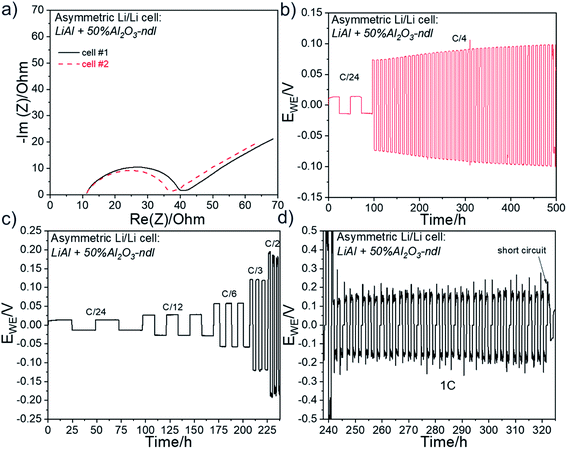
After pointed out the beneficial effect of the needle-like Al2O3 ceramic, symmetric Li/Li cells were assembled. The electrochemical performance are presented in Fig. 12. Firstly, the Nyquist plots show similar impedance profiles for the two cells and near of those obtained after assembling for the asymmetric cells presented in Fig. 9 and for the cell assembled with the lithium electrodes containing the 4 μm thick 85% Al2O3-sph ceramic layer (Fig. 8c). For all the cells, the electrolyte resistance is near of 10–12 Ω and the RCT is about 27–30 Ω after assembling. One of the cells was cycled at a constant charge/discharge rate of C/4. The results for the long cycling experiment are shown in Fig. 12b. The cell presented a perfect square shape for the stripping/plating of lithium for at least 500 hours with a slight increase of overvoltage over cycling. That represents a strong improvement in comparison to the reference cell, which was not able to cycle correctly at C/4 for few cycles (see Fig. 6b). The second cell was cycled at different C-rates and continuously at 1C as presented in Fig. 12c and d. It is worth noting that in this case, a symmetrical behavior is well observed in contrast to the cell of Fig. 9d. That confirms the protective effect of the ceramic layer against the deformation of the lithium/SPE interface as well as the rapid formation of dendrite. Finally, the cell short-circuited after about 320 h of cycling and almost 86 h at 1C. As discussed above, although the ceramic layer composed of Al2O3-ndl is less compact, uniform and composed of less quantity of ceramic (50%) in comparison to the layer made with Al2O3-sph (up to 85%), the results seem more promising. Such performance improvements (i.e. lower polarization, longer cycle life and capability to cycle at higher current densities) are often reported in the literature when CPEs or ceramic overcoatings on Li surface are used. For instance, Shi et al. showed that the cycling lifetime of symmetrical Li/Li cells was extended three times longer with TiO2-based CPE (∼1.2 wt% of TiO2) and nine-fold to SPE when an ultrathin Al2O3 layer is deposited by ALD on the surface of the CPE.40 The authors argue that Al2O3 layer has an excellent contact with lithium metal and the spontaneous formation of a Li–Al–O ionic conductor layer when Al2O3 is in contact with lithium increases the Li+ transfer number as well as the ionic conductivity. The same conclusion is done by Zhao et al. with their LiAlO2-PVDF coated lithium, except that the bare and the modified lithium foils were tested with a liquid electrolyte.42 The protected lithium achieved an ultra-long lifespan and correctly ran for more than 1600 h at 1 mA cm−2 in symmetrical Li/Li cells while the reference cell died after 1350 h. An excellent recent work of Armand and co-authors showed that a CPE with Al2O3 fillers improves the stability of the Li/electrolyte interface.41 However, they report that a too high quantity of ceramic (i.e., 20 wt%) dramatically affects the Li ion conductivity. By incorporating Al2O3 ceramic, the lifespan of symmetrical Li/Li cell is extended five-fold in comparison to the reference cell.Additional tests with the Mg2B2O5 ceramic were performed and a clear improvement of performance was also concluded, as shown in Fig. S8,† for an aged lithium with a ∼6 μm thick 70% Mg2B2O5 ceramic layer. This ceramic seems really promising for improving the lithium stability, but more tests are still ongoing to improve its deposition and to understand the chemical reactions occurring at the Li surface.
3.6 Validation of the fabrication process
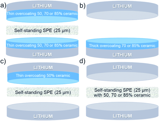
Since the effect of a thin layer of ceramic between the lithium and the SPE was demonstrated to stabilize the cycling, other experiments were performed to demonstrate or not if the same effect was observed with thick ceramics layers deposited on lithium or with self-standing SPE containing high quantity of ceramics.Firstly, thick overcoatings of Al2O3-sph (70 and 85%) were deposited on the surface of the LiAl foil. Typical SEM images for the two LiAl surfaces and composed of: (a) 70% Al2O3-sph (∼15–20 μm) and (b) 85% Al2O3-sph (∼15 μm) are shown in Fig. 4. Then, these coated lithium foils were assembled with a pristine lithium without the use of additional SPE as represented in Scheme 1b. The assembling with the lithium containing the 85% Al2O3-sph layer was roughly possible due to the formation of cracks on the surface during the pressing step, and this configuration was abandoned. By chance, a cell was still assembled, and the electrochemical performance are shown in Fig. S9 in the ESI.† The cell presented a huge charge transfer resistance of 4.9 × 10⁴ Ω and was not able to perform just one cycle at a C/24. In contrast, it was a success for the assembling using the lithium with the 70% Al2O3-sph layer. The electrochemical results are available in Fig. S10.† In comparison to the reference cells (see Fig. 6), the reproducibility was not good, and no clear improvement was observed. These observations demonstrate the interest of thin layers of ceramic on lithium surface, which undergo less constraint during lithium manipulation and pressing step. In addition, the lithium-ion diffusion in a thick layer of polymer/ceramic is not as efficient as for a ceramic-free SPE. For this point, there is a clear interest to combine a self-standing SPE for its good ionic conductivity with a thin ceramic-rich interlayer for its ability to stabilize the SPE/lithium interface. Moreover, thick ceramic-rich overcoatings are less sticky even during the hot-pressing step at 80 °C that results in strong interfacial resistance.
The second strategy consisted to form the ceramic-rich SPE on a polypropylene film and take-off it to use as a self-standing electrolyte. The typical assembling is represented in Scheme 1d. Unfortunately, the 25 μm thick SPEs made with 50% Al2O3-ndl and 85% Al2O3-sph ceramics were not successfully retired from the polypropylene substrate without destruct them. Only the SPE made with 70% Al2O3-sph was manipulable. The electrochemical performance for two cells are shown in Fig. S11.† The electrolyte resistance was several times higher than that obtained for the reference cells (see Fig. 6) as expected for a SPE with a high amount of ceramic and the performance were worse since the coin-cell was not even able to cycle at C/12.
3.7 Cycling of complete LFP/SPE/Li polymer batteries
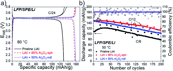
In a last step of this work, the modified lithium electrodes were tested in full cell with an LFP/SPE/Li configuration. A SEM image of the cross-sectional view of the LFP/SPE/Li stacking is shown in Fig. S12.† An intimate contact between each component of the battery is clearly visible with a low porosity for the cathode, which is mandatory in solid-state technology. Electrochemical results for LFP/SPE/Li batteries made with a pristine LiAl and modified LiAl electrodes with a ∼5 μm thick 50% Al2O3-ndl and a ∼4 μm thick 85% Al2O3-sph ceramic layers, are presented in Fig. 13. Firstly, the charge/discharge curves for the three cells obtained at C/24 and 80 °C during the formation step are shown in Fig. 13a. The galvanostatic profiles clearly indicate a single and long reversible plateau around 3.4 V vs. Li/Li+. This corresponds to the electrochemical activity of Fe3+/Fe2+ in the ordered olivine structure based on the two-phase reaction between LiFePO4 and FePO4.43 For the cell assembled with the pristine LiAl electrode, the discharge capacity at C/24 is quite low and reaches only 129 mA h g−1. In contrast, for the batteries made with ceramic layers, about 158 mA h g−1 was obtained, which is the practical discharge capacity for this carbon-coated LFP.44 Clearly, this interlayer has two roles. Firstly, it has an evident role against the progression of dendrites as demonstrated above with the cycling of symmetrical Li/Li cells. Secondly, it reduces the charge-transfer resistance between the SPE and the lithium surface. The deposition of a layer of polymer containing the ceramic permits to create a dense layer of ceramic that remains solid at room temperature but enough sticky during the pressing step at 80 °C. This behavior led to a better contact between the SPE and the lithium electrode while providing a strong barrier against dendrites. We already reported the similar beneficial effect of such a polymer interlayer between lithium and a solid oxide electrolyte.11 However, for each kind of ceramic, the good polymer/ceramic ratio as well as the optimal thickness must be determined. The layer must be the more concentrated in ceramic as possible to permit a strong effect against the progression of dendrites but not too much to avoid the layer to crumble during pressing. In addition, a minimal quantity of polymer is needed for the cohesion of the ceramic and to stick with the SPE during pressing. Compact and thin layers are preferred to thick ones to reduce the distance for the Li+ ions diffusion between the cathode and the anode. Moreover, we demonstrated that thick layers of the polymer/ceramic blends are not advantageous for the electrochemical performance (see Fig. S9–S11 in the ESI†).The cells were then cycled for 200 cycles at a C/6 rate and 50 °C, the results are shown in Fig. 13b. Firstly, for the batterie assembled with the pristine LiAl electrode, a gradual activation of the capacity was observed on the first 40 cycles with a low coulombic efficiency ranging from 80 to almost 100%. This is clearly due to the problems of adhesion between the LiAl foil and the SPE and to the poor ability of the ceramic-free SPE to manage the deformation of the anode side during the stripping/plating process. The initial capacity of 110 mA h g−1 slightly increased over cycling to reach a maximum of 122 mA h g−1 after 40 cycles. Then a rapid loss of capacity was observed on the following 160 cycles. At the end of the cycling, the discharge capacity was only of 78 mA h g−1, which represents a loss of 0.28 mA h per cycle. For the two cells assembled with the ceramic-modified lithium foils, the initial discharge capacities were similar and near of 150 mA h g−1. In addition, the coulombic efficiencies were much better and more stable (almost 100%) during the first cycles in comparison to the reference cell, indicating the efficiency of the ceramic layers against the progression of dendrites and deformation of the anode. The cells still presented a gradual loss of capacity over the cycles but less important than for the battery made with the unmodified LiAl foil. In fact, losses of 0.20 and 0.18 mA h per cycle were calculated for the cells made with the modified LiAl electrodes with a ∼5 μm thick 50% Al2O3-ndl and a ∼4 μm thick 85% Al2O3-sph ceramic layers, respectively. These results are consistent with those for symmetric Li/Li cells and confirmed the interest of ceramic-rich interlayers to increase the durability of solid-state batteries. Judez et al. also reported better coulombic efficiencies during cycling at low C-rates (C/10) for their Li–S batteries with a Al2O3-based CPE.41 However, the capacity loss in comparison to the reference cell seems similar if not worse. Similarly to our work, Shi et al. showed that Li–S batteries made with Al2O3-based CPEs had better coulombic efficiency and capacity retention. The modified cell performed 130 cycles at C/10 and 60 °C with a relatively good capacity retention and a stable coulombic efficiency near of 99% when the reference cell failed after only 18 cycles.40 Finally, Zhao et al. demonstrated that their LiAlO2-PVDF@Li anode delivers an ultra-long lifespan in the LiAlO2-PVDF@Li/LFP full cell.42 The durability at a 3C rate for the cell with the modified Li anode has been doubled in comparison to the reference cell.
Additional results are presented in Fig. S13† for LFP/SPE/LiMg batteries made with a pristine LiMg electrode and a modified LiMg electrode with a ∼4 μm thick 85% Al2O3-sph ceramic layer. The same improvement of the coulombic efficiency and the durability was observed by using the ceramic-modified anode. The cell with the pristine LiMg electrode showed a sharp decrease of the coulombic efficiency value after 125 cycles and short-circuited after only 170 cycles. In contrast, thanks to the ceramic layer, the cell with the modified lithium still delivered a discharge capacity of 100 mA h g−1 after 180 cycles, representing a loss of 0.17 mA h per cycle against 0.26 mA h per cycle for the reference cell.
4 Conclusions and perspectives
Thin layers (4 μm and more) of polymer/ceramic blends with high amount of ceramic (up to 85%) were successfully deposited by doctor blading process on lithium foil surface. The influence of various shapes (needle, sphere, rod) and types of ceramic (Al2O3, Mg2B2O5) was studied. As results, “polymer in ceramic” layers were obtained, providing a strong barrier against the progression of dendrite as well as a buffer layer to alleviate the lithium deformation during the stripping/plating process. The ceramic-modified lithium foils were electrochemically validated in symmetrical Li/SPE/Li and full all-solid-state LFP/SPE/Li batteries. It was observed for all the cells that the charge transfer resistance was significantly reduced after the deposition of the polymer/ceramic layers on lithium surface. In addition, the symmetrical cells were able to cycle at higher C-rates and the durability at C/4 was even improved by a factor of 8. SEM observations of Li/SPE/Li stacks after cycling revealed that the polymer/ceramic interlayer reduces the deformation of lithium upon cycling and avoids the formation of dendrites. Finally, LFP/SPE/Li batteries were cycled and better coulombic efficiencies as well as capacity retentions were obtained with the modified lithium electrodes. Interestingly, the protected LiMg alloy anode also presented an improvement of the cycling that confirms this simple method can be generalized for all types of metallic anodes.In this work, we demonstrated the double advantageous of thin polymer/ceramic interlayer to improve the contact between the SPE and the anode surface during the hot-pressing step and to impede the progression of dendrite and deformation of lithium/SPE interface. However, the design of the interlayer must be well thought and strongly depends on the type of ceramic used (sphere versus needle or other shapes), the polymer/ceramic ratio desired and its thickness. Typically, the layer must be the more concentrated in ceramic as possible to permit a strong effect against the progression of dendrites but not too much to avoid its collapse during pressing. In parallel, a minimal quantity of polymer is needed for the cohesion of the ceramic and to ensure a good contact with the SPE during pressing. In addition, the interlayers must be the most compact and the thinner possible to reduce the Li+ ion diffusion distance between the two electrodes. In contrary to most of the solutions to protect the lithium surface,45 the casting method involving the preparation of a ink is a well-known and widely used process by industrials to prepare electrodes. This easy method for protect lithium is cheap, easy to scale up and realizable in a roll-to-roll process.
Finally, to complete this work, it would be interesting to study in depth the influence of ceramic particle shape and size on the electrochemical performance. Evidently, the next step should be to incorporate Li+ ion conductive ceramics such as LLZO that is known to be stable upon lithium.46 To better alleviate the lithium deformation during cycling and to accommodate the volume change, elastic polymer could be used in the composition of the interlayer.47
Author contributions
Nicolas Delaporte: conceptualization; formal analysis; investigation; methodology; supervision; project administration; validation; visualization; writing – original draft; writing – review & editing. Gilles Lajoie: resources; methodology; investigation. Ali Darwiche: data curation; formal analysis; investigation; validation; visualization. Marie-Josée Vigeant: resources; investigation. Steve Collin-Martin: resources; investigation. Daniel Clément: resources; investigation.Conflicts of interest
The authors declare that they have no financial or other personal interests that could have appeared to influence the work reported in this paper.Acknowledgements
This work was financially supported by Hydro-Québec. The laboratory experiments were conducted at the Center of Excellence in Transportation, Electrification, and Energy Storage (CETEES). Nancy Turcotte and Hugues Levesque are graciously thanked for their help to prepare the thin Li, LiAl and LiMg foils. This work is patent-pending (WO2021/159209A1).References
- B. Llamas, M. F. Ortega, G. Barthelemy, I. de Godos and F. G. Acién, Development of an efficient and sustainable energy storage system by hybridization of compressed air and biogas technologies (BIO-CAES), Energy Convers. Manage., 2020, 210, 112695 CrossRef CAS.
- J.-M. Tarascon and M. Armand, Issues and challenges facing rechargeable lithium batteries, Nature, 2001, 414, 359–367 CrossRef CAS PubMed.
- G. Bauer, C. Zheng, J. B. Greenblatt, S. Shaheen and D. M. Kammen, On-Demand Automotive Fleet Electrification Can Catalyze Global Transportation Decarbonization and Smart Urban Mobility, Environ. Sci. Technol., 2020, 54, 7027–7033 CrossRef CAS PubMed.
- C. Sun, J. Liu, Y. Gong, D. P. Wilkinson and J. Zhang, Recent advances in all-solid-state rechargeable lithium batteries, Nano Energy, 2017, 33, 363–386 CrossRef CAS.
- A. Varzi, R. Raccichini, S. Passerini and B. Scrosati, Challenges and prospects of the role of solid electrolytes in the revitalization of lithium metal batteries, J. Mater. Chem. A, 2016, 4, 17251–17259 RSC.
- W. Xu, et al., Lithium metal anodes for rechargeable batteries, Energy Environ. Sci., 2014, 7, 513–537 RSC.
- J. Schnell, et al., All-solid-state lithium-ion and lithium metal batteries – paving the way to large-scale production, J. Power Sources, 2018, 382, 160–175 CrossRef CAS.
- J. Janek and W. G. Zeier, A solid future for battery development, Nat. Energy, 2016, 1, 1–4 Search PubMed.
- M. Rosso, et al., Dendrite short-circuit and fuse effect on Li/polymer/Li cells, Electrochim. Acta, 2006, 51, 5334–5340 CrossRef CAS.
- K. H. Kim, et al., Characterization of the interface between LiCoO2 and Li7La3Zr2O12 in an all-solid-state rechargeable lithium battery, J. Power Sources, 2011, 196, 764–767 CrossRef CAS.
- N. Delaporte, et al., Facile Protection of Lithium Metal for All-Solid-State Batteries, ChemistryOpen, 2019, 8, 192–195 CrossRef CAS PubMed.
- R. C. Xu, et al., Interfacial challenges and progress for inorganic all-solid-state lithium batteries, Electrochim. Acta, 2018, 284, 177–187 CrossRef CAS.
- D. Bosubabu, J. Sivaraj, R. Sampathkumar and K. Ramesha, LAGP|Li Interface Modification through a Wetted Polypropylene Interlayer for Solid State Li-Ion and Li–S batteries, ACS Appl. Energy Mater., 2019, 2, 4118–4125 CrossRef CAS.
- R. Pathak, et al., Fluorinated hybrid solid-electrolyte-interphase for dendrite-free lithium deposition, Nat. Commun., 2020, 11, 93 CrossRef CAS PubMed.
- R. Xu, et al., Artificial Soft–Rigid Protective Layer for Dendrite-Free Lithium Metal Anode, Adv. Funct. Mater., 2018, 28, 1705838 CrossRef.
- C. C. Tambelli, et al., Characterisation of PEO–Al2O3 composite polymer electrolytes, Electrochim. Acta, 2002, 47, 1677–1682 CrossRef CAS.
- P. Yao, et al., Review on Polymer-Based Composite Electrolytes for Lithium Batteries, Front. Chem., 2019, 7, 522 CrossRef CAS PubMed.
- P. Pal and A. Ghosh, Influence of TiO2 nano-particles on charge carrier transport and cell performance of PMMA-LiClO4 based nano-composite electrolytes, Electrochim. Acta, 2018, 260, 157–167 CrossRef CAS.
- D. Lin, et al., High Ionic Conductivity of Composite Solid Polymer Electrolyte via In Situ Synthesis of Monodispersed SiO2 Nanospheres in Poly(ethylene oxide), Nano Lett., 2016, 16, 459–465 CrossRef CAS PubMed.
- B. Liang, et al., Preparation and characterization of PEO-PMMA polymer composite electrolytes doped with nano-Al2O3, Electrochim. Acta, 2015, 169, 334–341 CrossRef CAS.
- O. Sheng, et al., Mg2B2O5 Nanowire Enabled Multifunctional Solid-State Electrolytes with High Ionic Conductivity, Excellent Mechanical Properties, and Flame-Retardant Performance, Nano Lett., 2018, 18, 3104–3112 CrossRef CAS PubMed.
- W. Liu, D. Lin, J. Sun, G. Zhou and Y. Cui, Improved Lithium Ionic Conductivity in Composite Polymer Electrolytes with Oxide-Ion Conducting Nanowires, ACS Nano, 2016, 10, 11407–11413 CrossRef CAS PubMed.
- X. Zhang, et al., Synergistic Coupling between Li6.75La3Zr1.75Ta0.25O12 and Poly(vinylidene fluoride) Induces High Ionic Conductivity, Mechanical Strength, and Thermal Stability of Solid Composite Electrolytes, J. Am. Chem. Soc., 2017, 139, 13779–13785 CrossRef CAS PubMed.
- P. Zhu, et al., Li0.33La0.557TiO3 ceramic nanofiber-enhanced polyethylene oxide-based composite polymer electrolytes for all-solid-state lithium batteries, J. Mater. Chem. A, 2018, 6, 4279–4285 RSC.
- L. Yang, et al., Flexible Composite Solid Electrolyte Facilitating Highly Stable “Soft Contacting” Li–Electrolyte Interface for Solid State Lithium-Ion Batteries, Adv. Energy Mater., 2017, 7, 1701437 CrossRef.
- Y. Zhao, et al., A promising PEO/LAGP hybrid electrolyte prepared by a simple method for all-solid-state lithium batteries, Solid State Ionics, 2016, 295, 65–71 CrossRef CAS.
- T. Thieu, et al., Long cycle-life prototype lithium-metal all-solid-state pouch cells employing garnet-rich composite electrolyte, Electrochim. Acta, 2021, 397, 139249 CrossRef CAS.
- Y. Zhao, et al., A new solid polymer electrolyte incorporating Li10GeP2S12 into a polyethylene oxide matrix for all-solid-state lithium batteries, J. Power Sources, 2016, 301, 47–53 CrossRef CAS.
- A. Parejiya, et al., Improving Contact Impedance via Electrochemical Pulses Applied to Lithium–Solid Electrolyte Interface in Solid-State Batteries, ACS Energy Lett., 2021, 6, 3669–3675 CrossRef CAS.
- Y. Liu, et al., An Artificial Solid Electrolyte Interphase with High Li-Ion Conductivity, Mechanical Strength, and Flexibility for Stable Lithium Metal Anodes, Adv. Mater., 2017, 29, 1605531 CrossRef PubMed.
- D. J. Lee, et al., Composite protective layer for Li metal anode in high-performance lithium–oxygen batteries, Electrochem. Commun., 2014, 40, 45–48 CrossRef CAS.
- H.-K. Jing, L.-L. Kong, S. Liu, G.-R. Li and X.-P. Gao, Protected lithium anode with porous Al2O3 layer for lithium–sulfur battery, J. Mater. Chem. A, 2015, 3, 12213–12219 RSC.
- Z. Peng, et al., Volumetric variation confinement: surface protective structure for high cyclic stability of lithium metal electrodes, J. Mater. Chem. A, 2016, 4, 2427–2432 RSC.
- N. Delaporte, et al., Alumina-flame retardant separators toward safe high voltage Li-Ion batteries, J. Power Sources, 2021, 506, 230189 CrossRef CAS.
- S. Fujiwara, Y. Tamura, H. Maki, N. Azuma and Y. Takeuchi, Development of New High-Purity Alumina, https://www.sumitomo-chem.co.jp/english/rd/report/files/docs/20070102_fth.pdf Search PubMed.
- L. Wang, et al., Long lifespan lithium metal anodes enabled by Al2O3 sputter coating, Energy Storage Mater., 2018, 10, 16–23 CrossRef.
- Y. Zhao, et al., Robust Metallic Lithium Anode Protection by the Molecular-Layer-Deposition Technique, Small Methods, 2018, 2, 1700417 CrossRef.
- L. Chen, et al., Lithium metal protected by atomic layer deposition metal oxide for high performance anodes, J. Mater. Chem. A, 2017, 5, 12297–12309 RSC.
- E. Kazyak, K. N. Wood and N. P. Dasgupta, Improved Cycle Life and Stability of Lithium Metal Anodes through Ultrathin Atomic Layer Deposition Surface Treatments, Chem. Mater., 2015, 27, 6457–6462 CrossRef CAS.
- Y. Shi, et al., Atomic-scale Al2O3 modified PEO-based composite polymer electrolyte for durable solid-state Li–S batteries, J. Electroanal. Chem., 2021, 114916 CrossRef CAS.
- X. Judez, et al., Polymer-Rich Composite Electrolytes for All-Solid-State Li–S Cells, J. Phys. Chem. Lett., 2017, 8, 3473–3477 CrossRef CAS PubMed.
- Q. Zhao, et al., A facile, scalable, high stability Lithium metal anode, SusMat, 2022, 2, 104–112 CrossRef.
- J. Humberto, D. K. Thomas, Z. Karim and P. Jai, Electrochemical and Thermal Studies of Carbon-Coated LiFePO4 Cathode, J. Electrochem. Soc., 2009, 156, A401–A406 CrossRef.
- N. Delaporte, L. Gilles, C.-M. Steve and Z. Karim, Toward Low-Cost All-Organic and Biodegradable Li-Ion Batteries, Sci. Rep., 2020, 10, 3812 CrossRef CAS PubMed.
- N. Delaporte, Y. Wang and K. Zaghib, Pre-treatments of Lithium Foil Surface for Improving the Cycling Life of Li Metal Batteries, Front. Mater., 2019, 6, 267 CrossRef.
- J. Wolfenstine, J. L. Allen, J. Read and J. Sakamato, Chemical stability of cubic Li7La3Zr2O12 with molten lithium at elevated temperature, J. Mater. Sci., 2013, 48, 5846–5851 CrossRef CAS.
- Q. Pang, L. Zhou and L. F. Nazar, Elastic and Li-ion–percolating hybrid membrane stabilizes Li metal plating, PNAS, 2018, 115, 12389–12394 CrossRef CAS PubMed.
Footnote |
| † Electronic supplementary information (ESI) available. See https://doi.org/10.1039/d2ra01856j |
| This journal is © The Royal Society of Chemistry 2022 |

