 Open Access Article
Grafting of thermotropic fluorinated mesogens on polysiloxane to improve the processability of linear low-density polyethylene†
Wenqing Wu *a,
Pan Li*b,
Xiaohang Wangc and
Baoyan Zhangd
aSchool of Materials Science and Engineering, Northeastern University, Shenyang 110819, China. E-mail: wwq714wwq714@126.com
bSchool of Chemistry and Chemical Engineering, Hefei Normal University, Hefei 230601, China. E-mail: panli_hfnu@126.com
cChina Chemical Technology Research Institute, Beijing 100029, China
dCenter for Molecular Science and Engineering, Northeastern University, Shenyang 110819, China
First published on 25th April 2022
Abstract
In this study, a series of polysiloxane grafted with thermotropic fluorinated mesogens (TSCPFLCP) is designed and synthesized. The TSCPFLCP exhibits a typical smectic liquid crystal phase, and shows a high thermal decomposition temperature at 335.6 °C. After blending with LLDPE, the balance melt torque of LLDPE/TSCPFLCP is decreased by 42% at 0.5 wt% TSCPFLCP, and the corresponding power law index is increased to 0.45. The flowing activation energy of the optimized LLDPE/TSCPFLCP blend is lower than that of pure LLDPE at the same shear rate, indicating that TSCPFLCP reduced the sensitivity of the apparent melt viscosity of LLDPE to both shear rate and temperature. This contributes to the broadening of the LLDPE processing window. On the other hand, TSCPFLCP is also found beneficial in ameliorating melt fracture during LLDPE extrusion. Furthermore, the mechanical properties of LLDPE/TSCPFLCP blends, such as tensile strength, elastic modulus and elongation at break, are also enhanced significantly at 0.5 wt% TSCPFLCP. Altogether, TSCPFLCP has been proven an effective processing aid to improve the processability and toughness of LLDPE.
1. Introduction
To improve the processability of thermoplastic composites,1,2 processing aids such as linear polydimethylsiloxane (PDMS) are frequently used in the production process due to their lubrication effect for plastics.3,4 For instance, a minuscule amount of polysiloxane bearing long-chain alkyl side groups can significantly increase the melt flow rate to facilitate the processing process.5 However, PDMS is a typical liquid polymer and cannot be conveniently handled in industrial production. As an alternative processing aid, thermotropic liquid crystalline polymer (TLCP) also exhibits excellent lubricating properties for thermoplastic polymer melts.6–9 In the melting process, TLCPs in the liquid crystal phase are easily oriented and arranged along the flow direction under the action of shear force or tension, therefore improving the processability of thermoplastic composites.10–14Nevertheless, the main drawback of most main chain TLCPs is the high melting temperature, and it greatly confines their use to engineering plastics which are tolerant of higher processing temperature.15 In this regard, only few main chain TLCPs meet the requirement of low processing temperature system, such as polyolefin based thermoplastic composites.16 Therefore, reducing the melting point of TLCPs is highly desirable to broaden their application.17 On the other hand, ameliorating the melt fracture and reducing the extruder head pressure are also crucial to improve the polyolefins production efficiency. These improvements can be potentially achieved by integrating fluorinated compounds on TLCPs due to their excellent lubricating properties for processing thermoplastic materials.18,19 To address these practical issues, we assume that a polysiloxane grafted by thermotropic fluorinated mesogenic unit (TSCPFLCP) is a new kind of powdered processing aid with low and tunable melting temperature. This is because TSCPFLCP comprises both the flexible PDMS segment as main chain and thermotropic mesogens on polymer side chain. Such a featured polymeric structure has been demonstrated to adjust the melting temperature between 15 ∼ 200 °C,20 and the isotropic temperature between 84 ∼ 300 °C.21,22 Meanwhile, the introduction of polar fluorine group is expected to significantly reduce the melt fracture during the processing of polyolefin.
Compared with PDMS and main chain TLCPs, TSCPFLCPs show potential advantages in industrial production, however, no related work has been reported to the author's knowledge. In the current work, a series of TSCPFLCPs with low melting temperature were successfully synthesized to blend with linear low-density polyethylene (LLDPE). The influence of TSCPFLCP loading on the processing and tensile properties of composite materials were investigated. In addition, the modification mechanism of LLDPE by TSCPFLCP under different processing temperatures, rotating speeds and shear rates was also studied to provide guidance for industrial processing. Overall, this study provides a feasible scheme for the synthesis of well-structured liquid crystal polymers to meet the special needs of plastic processing.
2. Experiment
2.1 Materials
(Trans, trans)-4-(3,4-difluorophenyl)-4′-vinyl-1,1′ bi(cyclo-hexane) (M1) (Tm: 50.6 °C,Ti: 109.4 °C) and 1-but-3-enyl-4-(4-propylcyclohexyl)cyclohexane (M2) (Tm: 74.8 °C, Ti: 79.2 °C) were purchased from Bayi Space LCD Technology (Beijing, China) Co., Ltd. Poly(methylhydrogeno)siloxane (PMHS, Mn = 582, Mw = 595, PDI = 1.02) were purchased from Aladdin Chemical Reagent Co., Ltd (Shanghai, China). Linear low-density polyethylene (LLDPE, DFDA 7042, MFI = 2.0 g/10 min, Mn = 30![[thin space (1/6-em)]](https://www.rsc.org/images/entities/char_2009.gif) 400, Mw = 122
400, Mw = 122![[thin space (1/6-em)]](https://www.rsc.org/images/entities/char_2009.gif) 200, PDI = 4.02) was produced by Sinopec Guangzhou Co., Ltd (Guangzhou, China). Toluene, ethanol, tetrahydrofuran (THF) and methanol were purchased from Shenyang Chemical Co., Ltd (Shenyang, China).
200, PDI = 4.02) was produced by Sinopec Guangzhou Co., Ltd (Guangzhou, China). Toluene, ethanol, tetrahydrofuran (THF) and methanol were purchased from Shenyang Chemical Co., Ltd (Shenyang, China).
2.2 Instruments
Fourier transform infrared spectra (FT-IR) were measured on PerkinElmer instruments Spectrum One Spectrometer (PerkinElmer, Foster City, CA, USA) after compressing samples into KBr pellets. 1H-NMR was tested by a Varian WH-90PFT NMR Spectrometer (Varian Associates, Palo Alto, CA) with CDCl3 and tetramethylsilane (TMS) as an internal standard. The thermal properties and curing studies were carried out with a NETZSCH Instruments DSC 204 (Netzsch, Wittelbacherstrasse, Germany) at heating and cooling rate of 10 °C min−1 under nitrogen atmosphere. The texture of monomers and cured products were observed with a polarized optical microscope (POM) (Leica, Wetzlar, Germany) equipped with a Linkam THMSE-600 (Linkam, Surrey, UK) hot stage connected to a TP-92 temperature control unit. Wide-angle X-ray diffraction measurements were performed on a DMAX-3A Rigaku powder diffractometer (Rigaku, Japan). X-ray experiments on crosslinked samples were performed at room temperature. The balance torque of LLDPE/TSCPFLCP composite melt was determined by Haake torque XSS-300 rheometer (Thermo, Germany) at a rotation speed from 10 to 50 rpm. The test temperature was set at 160, 165, 170, 175, and 180 °C, respectively. The rheological properties were measured by a high-pressure capillary rheometer (Rheologic 5000, Ceast, Italy) with a length-to-diameter ratio of 30/1. The tests were performed in a shear rate ranging from 10 to 1500 s−1 at 160, 165, 170, 175, and 180 °C, respectively. Morphology and structure of LLDPE/TSCPFLCP blends were observed by scanning electron microscope (SEM, JEOL JSM-5900LV, Japan) and transmission electron microscope (TEM, JEOL JEM-1011, Japan). The samples were fractured in liquid nitrogen, and the fracture surfaces were coated with gold to prevent charging on the surface. Tensile properties of LLDPE/TSCPFLCP blends were measured by an Instron 5967 model materials testing system (USA) according to ASTM D-638 standard. Samples of tension test were dumbbell-shaped and the direction of the tensile force was parallel to the length of samples.2.3 Synthesis of TSCPFLCPs
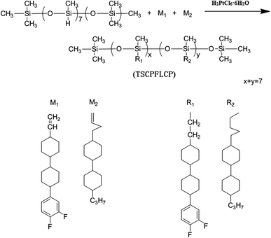
M1, M2 and PMHS were dissolved in toluene (50 mL) according to the specific feeding proportion as shown in Table 1, then 2.5 mL of H2PtCl6·6H2O/isopropyl alcohol (0.5 g of hexachloroplatinic acid hydrate dissolved in 100 mL of isopropyl alcohol) was slowly added into the above solution. The reaction proceeded for 72 h at 75 °C under nitrogen and was monitored by FT-IR until the disappearance of the sharp vibrational band at 2166 cm−1 assigned as the Si–H stretching. The reaction was ceased by precipitating the mixture into methanol to obtain the crude product, which was further purified by repeated precipitation from methanol after dissolving in chloroform. Finally, white powdery polymers (P1–P6) were obtained and the synthesis route were shown in Fig. 1.| Sample | PMHS (mmol) | M1 (mmol) | M2 (mmol) |
|---|---|---|---|
| P1 | 0.25 | 0.25 | 1.50 |
| P2 | 0.25 | 0.50 | 1.25 |
| P3 | 0.25 | 0.75 | 1.00 |
| P4 | 0.25 | 1.00 | 0.75 |
| P5 | 0.25 | 1.25 | 0.50 |
| P6 | 0.25 | 1.50 | 0.25 |
2.4 Preparation of LLDPE/TSCPFLCP blends
LLDPE was dried in a vacuum oven at 80 °C for 12 h prior to processing. The pre-mixed blend of LLDPE and TSCPFLCPs was conducted using a mixer (HAAKE, RS600, Germany) at a temperature of 170 °C and screw speed of 50 rpm for 5 min. After being pulverized and dried, the well-mixed composite was injection-molded into tensile testing bars using a mini-injection system (Thermo Scientific, USA) at melt temperature of 170 °C and the mold temperature of 30 °C. The compositions and code names of the samples were shown in Table 2.| Sample | LLDPE (g) | P6 (g) |
|---|---|---|
| LLDPE | 100 | — |
| LLDPE/P6-0.02% | 100 | 0.02 |
| LLDPE/P6-0.05% | 100 | 0.05 |
| LLDPE/P6-0.1% | 100 | 0.1 |
| LLDPE/P6-0.5% | 100 | 0.5 |
3. Results and discussion
3.1 Characterization of TSCPFLCP
Fig. 2a shows the FT-IR spectra of M1, M2 and the representative TSCPFLCP sample P6. It can be seen that the typical peak at 2166 cm−1 assignable to the Si–H peak of PMHS disappeared in P6, and the characteristic peak at 1640 cm−1 corresponding to the vinyl group of monomers also vanished. In addition, the newly formed Si–O–Si bond showed strong and wide bands between 1000 to 1120 cm−1. All these results indicate that the hydrosilylation reaction between PMHS and monomers proceeded successfully.23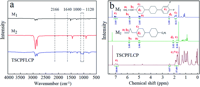 | ||
| Fig. 2 (a) FT-IR spectra of M1, M2 and TSCPFLCP, (b) 1H-NMR spectra of M1, M2 and TSCPFLCP in CDCl3. | ||
Fig. 2b shows 1H-NMR spectra of M1, M2 and P6. No vinyl signals of the two monomers at 4.97 and 5.80 ppm were found in the 1H-NMR spectrum of P6, which indicated that the excess monomers were completely removed and P6 was successfully obtained.24 Based on the integral of typical peaks, the grafted ratio of two monomers in P6 also agreed with the feed ratio.
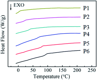
DSC experiment is used to examine the phase transition of synthesized TSCPFLCPs. Their heating curves the related data are compiled in Fig. 3 and Table 3, respectively. It can be seen from Fig. 3 that all TSCPFLCPs have obvious glass transition temperature (Tg), indicating they are amorphous liquid crystal polymers. It should be mentioned that no obvious clearing point was detected for the TSCPFLCPs series, which was likely attributed to the small enthalpy change during the liquid crystalline phase transition. With the increase of the content of fluorinated liquid crystal monomer M1, the Tg and the clearing temperature (Ti) of the polymer increase. The Tg of side chain liquid crystal polymers is closely related to the type of main chain, the rigidity and polarity of liquid crystal units, the volume of side chain groups and the length of flexible spacer connected to the main chain. As for these TSCPFLCPs, although their main chain type and pending flexible spacer have not changed greatly, the increase of rigid and polar M1 content still makes the movement of molecular segments difficult and leads to the gradual increase of Tg. On the other hand, the rigidity and polarity of fluorine-containing groups restrict their internal rotation, so that the polymers need more enthalpic compensation at higher temperature to drive the intermolecular orientation.
| Polymer | Thermal analysis | |||
|---|---|---|---|---|
| Tg (°C) | Ti (°C) | ΔT (°C) | Td (°C) | |
| P1 | −2.7 | 117.2 | 120.0 | 291.4 |
| P2 | 15.7 | 140.8 | 125.2 | 315.5 |
| P3 | 35.8 | 153.3 | 117.5 | 330.1 |
| P4 | 65.4 | 173.1 | 107.7 | 340.0 |
| P5 | 76.5 | 180.4 | 103.8 | 346.3 |
| P6 | 86.9 | 182.4 | 95.6 | 335.6 |
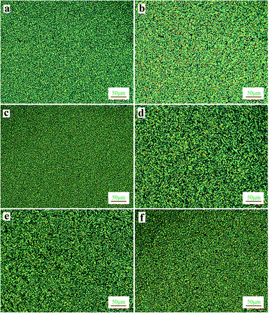
POM equipped with a hot stage is used to observe the liquid–crystalline transition and optical textures. Fig. 4 shows the POM images of TSCPFLCPs at different temperatures. Liquid crystal texture appeared during heating and cooling, indicating that TSCPFLCPs belong to thermotropic double variant liquid crystals. After increasing the temperature above the Tg, the polymer softened and color liquid crystal texture appeared, featuring the broken Schlieren texture of smectic phase. When heated to near the clear point, the crystalline texture disappeared gradually and the field of vision darkened.
Wide angle X-ray diffraction (WAXD) analysis was also performed to verify the crystalline structure. Fig. S1† displays the X-ray diffraction patterns of P6, and the two broad peaks at small angle (2θ ≈ 5.2°) and wide angle (2θ ≈ 20.3°) are characteristics of smectic phase.25
Fig. S2† shows the thermal decomposition process of TSCPFLCPs under nitrogen atmosphere. It revealed that Td (decomposition temperature at 5 wt% mass loss) are above 290 °C, respectively, indicating their high thermal stability.
Among all the TSCPFLCPs, the thermal properties of P6 (Tg = 86.9 °C, Ti = 182.4 °C, Td = 335.6 °C) perfectly meet the requirements of processing LLDPE composites (160 ∼ 250 °C), and therefore is selected for subsequent blending and extrusion with LLDPE.
3.2 Processability of LLDPE/TSCPFLCP blends
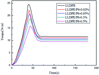
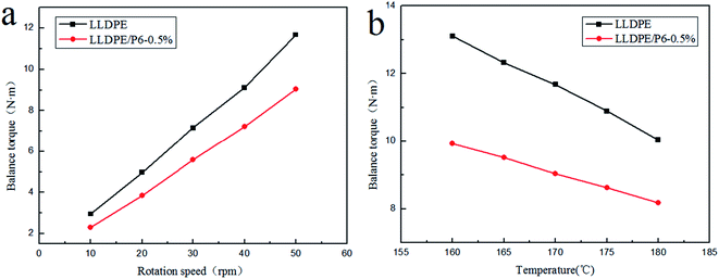
In order to study the influence of the external conditions, such as stress and temperature on the availability of TSCPFLCPs, samples P6-0.5% and LLDPE were selected as the research objects, and the melt torques at different temperatures and speeds were compared. The relationship between the balance torque and rotational speed of the blends at 170 °C is shown in Fig. 6a. It can be seen that the balance torque of LLDPE/P6-0.5% is lower than that of LLDPE, and their torque difference gradually increases with the increase of rotating speed. This result suggests that the molecular orientation of P6 conforms to the shear direction when there is sufficient shear force in the melt processing process. It therefore means that greater shear force will benefit TSCPFLCP orientation and composite processability.15,16 Fig. 6b shows the balance torque versus temperature curves for LLDPE and LLDPE/P6-0.5% at 50 rpm. With the rising of temperature, the balance torque of both LLDPE and LLDPE/P6-0.5% decreases significantly. Meanwhile, the balance torque of LLDPE/P6-0.5% is significantly lower than that of LLDPE at the same temperature, indicating that the superior processability of LLDPE/P6-0.5% within the whole processing temperature range. When the temperature increased from 160 °C to 180 °C, the balance torque of LLDPE and LLDPE/P6-0.5% decreased by 32.7% and 18.7% respectively. The results show that the addition of P6 reduces the sensitivity of LLDPE to processing temperature. The above results suggest that the processability of LLDPE/TSCPFLCP blends is affected not only by the TSCPFLCP content, but also by the rotational speed (shear force) and processing temperature, which are associated with the orientation of TSCPFLCP during processing.28
Fig. 7 shows the relationship between apparent viscosity and shear rate of LLDPE/TSCPFLCP blends and the relationship between shear stress and shear rate at 170 °C. It can be seen that within the experimental range of shear rate, the apparent viscosity and shear stress of the blends gradually decrease with the increase of TSCPFLCP content, which further proves that the addition of TSCPFLCP significantly improves the processability of LLDPE/TSCPFLCP blends.29
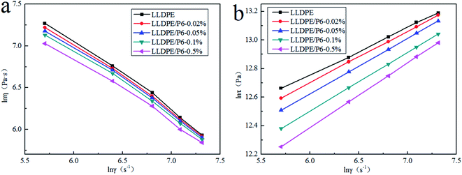 | ||
| Fig. 7 (a) Apparent viscosity versus shear rate at 170 °C, (b) shear stress versus shear rate at 170 °C. | ||
Fig. 7 shows that the logarithm of shear stress is in linear relationship with the logarithm of shear rate, indicating that the melt flow behavior with TSCPFLCP follows the power-law equation under experimental conditions.29 According to the power-law equation (t = Kγn), the power law exponent (n) of LLDPE/TSCPFLCP blends under different TSCPFLCP loads was calculated. As shown in Fig. S3,† the n values of LLDPE/TSCPFLCP blends are less than 1, indicating that the melt of LLDPE/TSCPFLCP blends is a pseudoplastic fluid. When the content of TSCPFLCP increased from 0% to 0.5%, the n value of LLDPE/TSCPFLCP blends increased from 0.33 to 0.45. The results showed that the non-Newtonian properties of LLDPE/TSCPFLCP blends decreased with the increase of TSCPFLCP load. On the basis of the above results, LLDPE/TSCPFLCP blends showed the following features with the increase of TSCPFLCP loads: (1) its non-Newtonian properties decreased; (2) the sensitivity of apparent melt viscosity to shear rate decreases and the processing window widens.
![[thin space (1/6-em)]](https://www.rsc.org/images/entities/char_2009.gif) exp(Ea/RT). Through logarithmic calculation of Arrhenius equation, we can get the following equation:
exp(Ea/RT). Through logarithmic calculation of Arrhenius equation, we can get the following equation:ln![[thin space (1/6-em)]](https://www.rsc.org/images/entities/char_2009.gif) η = ln η = ln![[thin space (1/6-em)]](https://www.rsc.org/images/entities/char_2009.gif) A + (Ea/R)(1/T) A + (Ea/R)(1/T) |
We plotted the logarithm of apparent viscosity ln![[thin space (1/6-em)]](https://www.rsc.org/images/entities/char_2009.gif) η and the reciprocal of temperature at different rotational speeds, and calculate the activation energy from the slope of the curve. Fig. 8 show the relationship between ln
η and the reciprocal of temperature at different rotational speeds, and calculate the activation energy from the slope of the curve. Fig. 8 show the relationship between ln![[thin space (1/6-em)]](https://www.rsc.org/images/entities/char_2009.gif) η and 1/T for LLDPE and LLDPE/P6-0.5%, respectively. Ln
η and 1/T for LLDPE and LLDPE/P6-0.5%, respectively. Ln![[thin space (1/6-em)]](https://www.rsc.org/images/entities/char_2009.gif) η is increased with 1/T, indicating that the viscosity of the composite melt is gradually decreased with the increase of the processing temperature. It is reasonable because the mobility of the molecular chains is increased under higher temperature, which suppresses the interaction force between molecular chains and thereby reduces the composite viscosity to improve fluidity.30
η is increased with 1/T, indicating that the viscosity of the composite melt is gradually decreased with the increase of the processing temperature. It is reasonable because the mobility of the molecular chains is increased under higher temperature, which suppresses the interaction force between molecular chains and thereby reduces the composite viscosity to improve fluidity.30
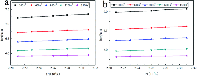 | ||
Fig. 8 The logarithm of apparent viscosity (ln![[thin space (1/6-em)]](https://www.rsc.org/images/entities/char_2009.gif) η) versus 1/T (a) pure LLDPE, (b) LLDPE/P6-0.5% at different shear rates. η) versus 1/T (a) pure LLDPE, (b) LLDPE/P6-0.5% at different shear rates. | ||
The linear curve of LLDPE at the shear rate of 300 s−1 is expressed by the following equation:
ln![[thin space (1/6-em)]](https://www.rsc.org/images/entities/char_2009.gif) η = 4.31 + 1315.3(1/T) η = 4.31 + 1315.3(1/T) |
Ea was determined to be 59.4 kJ mol−1 from the curve slop. We further calculated the flow activation energy and the linear correlation coefficient (R0) of other samples, which were listed in Table 4. It is found that the Ea value of LLDPE/P6-0.5% is lower than that of LLDPE at the same shear rate, indicating that LLDPE/P6-0.5% melt is easier to flow, which means 0.5wt% TSCPFLCP could obviously improve the processability of LLDPE. On the other hand, the Ea values of both LLDPE and LLDPE/P6-0.5% are continuously decreased with the increase of shear rate, which is attributed to the disentanglement between molecular chains at high shear rate.31,32
| γ(s−1) | 300 | 600 | 900 | 1200 | 1500 |
|---|---|---|---|---|---|
| Ea LLDPE (kJ mol−1) | 10.94 | 8.23 | 7.60 | 6.62 | 3.31 |
| Ea LLDPE/P6-0.5% (kJ mol−1) | 7.51 | 6.53 | 5.88 | 4.89 | 2.28 |
| R0 LLDPE | 0.9974 | 0.9905 | 0.9931 | 0.9976 | 0.9976 |
| R0 LLDPE/P6-0.5% | 0.9975 | 0.9975 | 0.995 | 0.9926 | 0.9691 |
3.3 Mechanical properties of TSCPFLCP blends
As the content of TSCPFLCP increased to 0.5 wt%, the tensile strength increased from 11.4 MPa to 12.6 MPa as shown in Fig. 10a; the elastic modulus of LLDPE containing 0.5% TSCPFLCP was 723.1 MPa, which was significantly increased by 41.6% compare with pure LLDPE. This is because the rigid elements contained in the TSCPFLCP side groups reinforce the composite materials. From Fig. 10b, the elongation at break of LLDPE/TSCPFLCP blends increased from 525% to 626% respectively. This is probably due to the polysiloxane structure in the TSCPFLCP macromolecular chain, as similar toughness strengthening has been observed in composites added with polydimethylsiloxane.35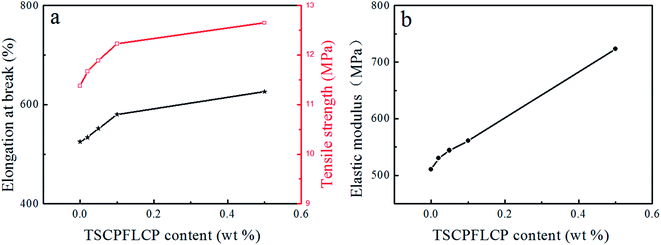 | ||
| Fig. 10 Effect of TSCPFLCP content on the mechanical properties of blends, (a) elongation at break and tensile modulus, (b) elastic modulus. | ||
3.4 The facture morphology of LLDPE/TSCPFLCP blends
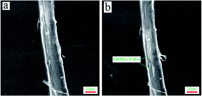
The influence of TSCPFLCP on the cross-sectional morphology of LLDPE/TSCPFLCP blends was studied by scanning electron microscope and transmission electron microscope. The results are shown in Fig. 11 and S4.† LLDPE was the continuous phase and TSCPFLCP was the dispersed phase. TSCPFLCP forms liquid crystal fibers in the matrix, which explains the improvement of mechanical properties of the blends after adding TSCPFLCP. Because of the poor compatibility between TSCPFLCP and LLDPE, liquid crystal fibers were pulled out of LLDPE matrix, generating noticeable holes on the fracture surface. In addition, more pores were observed in samples with higher TSCPFLCP content, indicating that the formation of more liquid crystal fibers is beneficial for blends processability.4. Conclusions
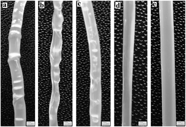
A series of polysiloxanes grafted by thermotropic fluorinated mesogenic unit (TSCPFLCP) were newly synthesized to blend with LLDPE for the purpose of improving its processability. Specifically, (1) the balance melt torque of LLDPE (11.85 N·m) decreases by 19.4% when only 0.5 wt% TSCPFLCP is employed in the LLDPE/TSCPFLCP blend; (2) the melt fracture of extrusion was also ameliorated obviously after amending polar fluorine moiety in TSCPFLCP; (3) the introduction of TSCPFLCP weakens the non-Newtonian properties of LLDPE and reduces the flow activation energy, widening the processing window and improves the processing performance. Moreover, the elongation at break of LLDPE increased significantly because of the flexible main chain of TSCPFLCP, accompanied with improvements on tensile strength and elastic modulus. Overall, the TSCPFLCPs have been demonstrated highly effective in improving the processability of LLDPE, offering an ideal processing aid to enhance its production efficiency.Conflicts of interest
There are no conflicts to declare.Notes and references
- A. Cardelli, G. Ruggeri, M. Calderisi, O. Lednev, C. Cardelli and E. Tombari, Polym. Degrad. Stab., 2012, 97, 2536–2544 CrossRef CAS.
- W. Zhou and J. Osby, Polymer, 2010, 51, 1990–1999 CrossRef CAS.
- T. J. Zolper, A. Seyam, Z. Li, C. Chen, M. Jungk, A. Stammer, T. J. Marks, Y. W. Chung and Q. Wang, Tribol. Lett., 2013, 51, 365–376 CrossRef CAS.
- Z. Kokuti, K. V. Gruijthuijsen, M. Jenei, G. T. Molnar and G. Szabo, Appl. Rheol., 2014, 24, 63984 Search PubMed.
- H. g. He, L. Gao, X. J. Yang, W. Guo, H. Li, T. Xie, S. K. Yang, J. P. Wang, Y. Zhang and X. Y. Yang, J. Fluorine Chem., 2013, 156, 158–163 CrossRef CAS.
- H. K. F. Cheng, T. Basu, N. G. Sahoo, L. Li and S. H. Chan, Polymers, 2012, 4, 889–912 CrossRef CAS.
- L. Zeng, R. Li, P. Chen, J. Xu and P. Liu, J. Appl. Polym. Sci., 2016, 133, 43800 Search PubMed.
- P. Wei, H. Lou, W. Wang, S. Geng and M. Jiao, Liq. Cryst., 2021, 48, 466–474 CrossRef CAS.
- K. Oh, H. Kim and Y. Seo, RSC Adv., 2019, 9, 12189–12194 RSC.
- C. Y. Ren and P. Gao, Polymer, 2012, 53, 3958–3967 CrossRef CAS.
- L. C. Wu, P. Chen, J. Chen, J. Zhang and J. S. He, Polym. Eng. Sci., 2007, 47, 757–764 CrossRef CAS.
- A. B. Samui, S. Pandey and S. P. Mishra, RSC Adv., 2015, 5, 68351 RSC.
- F. Chen, Y. Cong and B. Zhang, Liq. Cryst., 2016, 43, 1100 CrossRef CAS.
- X. Guan, B. Cao, J. Cai, Z. Ye, X. Lu, H. Huang, S. Liu and J. Zhao, Polymers, 2020, 12, 911 CrossRef CAS PubMed.
- A. K. Kalkar, V. D. Deshpande and M. J. Kulkarni, J. Polym. Sci., Polym. Phys., 2010, 48, 1070–1100 CrossRef CAS.
- Y. Rong, L. Chen, W. Q. Zhang, H. B. Chen and Y. Z. Wang, Polymer, 2011, 52, 4150–4157 CrossRef.
- Y. Xia, H. Zhang, Q. Wang, J. Guo and Y. Gong, J. Thermoplast. Compos. Mater., 2016, 29, 37–47 CrossRef CAS.
- D. R. Arda and M. R. Mackley, J. Non-Newtonian Fluid Mech., 2005, 126, 47–61 CrossRef CAS.
- C. W. Stewart, J. Rheol., 1993, 37, 499–513 CrossRef CAS.
- M. A. Apfel, H. Finkelmann, G. M. Janini, R. J. Laub, B. H. Luehmann, A. Price, W. L. Roberts, T. J. Shaw and C. A. Smith, Anal. Chem., 1985, 57, 651–658 CrossRef CAS.
- Y. Jin, R. Fu, Z. Guan, J. Gong and B. Li, J. Chromatogr. A, 1989, 483, 394–400 CrossRef CAS.
- H. Finkelmann, H. J. Kock and G. Rehage, Makromol. Chem., Rapid Commun., 1981, 2, 317–322 CrossRef CAS.
- J. S. Hu, B. Y. Zhang, A. J. Zhou, L. Q. Yang and W. Bai, Eur. Polym. J., 2006, 42, 2849–2858 CrossRef CAS.
- W. Yao, Y. Gao, C. Zhang, C. Li, F. Li, Z. Yang and L. Zhang, J. Polym. Sci., Polym. Chem., 2017, 55, 1765–1772 CrossRef CAS.
- W. Wu, Z. Li and B. Zhang, Liq. Cryst., 2021, 48, 1723–1732 CrossRef CAS.
- T. M. Malik, P. J. Carreau and N. Chapleau, Polym. Eng. Sci., 1989, 29, 600–608 CrossRef CAS.
- J. H. Chang, B. K. Choi, J. H. Kim, S. M. Lee and M. S. Bang, Polym. Eng. Sci., 2010, 37, 1564–1571 CrossRef.
- S. C. Hong, L. Yang and F. Gao, Compos. Sci. Technol., 2002, 62, 757–765 CrossRef.
- M. Nanda and D. K. Tripathy, J. Appl. Polym. Sci., 2012, 126, 46–55 CrossRef CAS.
- S. Thalib, S. Huzni, S. Fonna, C. H. Azhari and S. Zakaria, IOP Conf. Ser.: Mater. Sci. Eng., 2019, 602, 012086 CAS.
- N. Muksing, M. Nithitanakul, B. P. Grady and R. Magaraphan, Polym. Test., 2008, 27, 470–479 CrossRef CAS.
- M. Hemmati, G. H. Rahimi, A. B. Kaganj, S. Sepehri and A. M. Rashidi, J. Macromol. Sci. B., 2008, 47, 1176–1187 CrossRef CAS.
- F. N. Cogswell, J. Non-Newtonian Fluid Mech., 1977, 2, 37–47 CrossRef CAS.
- S. G. Hatzikiriakos, Polym. Eng. Sci., 1994, 34, 1441–1449 CrossRef CAS.
- X. Chen, J. Yu and S. Guo, J. Appl. Polym. Sci., 2006, 102, 4943–4951 CrossRef CAS.
Footnote |
| † Electronic supplementary information (ESI) available. See https://doi.org/10.1039/d2ra01482c |
| This journal is © The Royal Society of Chemistry 2022 |

