 Open Access Article
Using starch graft copolymer gel to assist the CO2 huff-n-puff process for enhanced oil recovery in a water channeling reservoir
Hongda Hao *a,
Dengyu Yuanb,
Jirui Houc,
Wenmin Guoa and
Huaizhu Liud
aSchool of Petroleum Engineering, Changzhou University, Changzhou, Jiangsu 213164, China. E-mail: haohongda90@126.com; Tel: +86 17601007653
bExploration and Development Research Institute, PetroChina Daqing Oilfield Company, Daqing, Heilongjiang 163000, China
cResearch Institute of Unconventional Oil & Gas Science and Technology, China University of Petroleum, Beijing 102249, China
dDrilling and Production Technology Research Institute, PetroChina Jidong Oilfield Company, Tangshan, Hebei 063000, China
First published on 8th July 2022
Abstract
The CO2 huff-n-puff process is an effective method to enhance oil recovery (EOR) and reduce CO2 emissions. However, its utilization is limited in a channeling reservoir due to early water and gas breakthrough. A novel starch graft copolymer (SGC) gel is proposed for treating the channels and assisting with the CO2 huff-n-puff process. Firstly, the bulk and dynamic performances of the SGC gel including rheology, injectivity and plugging ability are compared with the polymer gel in the laboratory. Then, 3D physical models with water channels are established to reveal the EOR mechanisms of gel assisted CO2 huff-n-puff. Several pilot tests of gel assisted CO2 huff-n-puff are also discussed in this paper. The bulk and dynamic experimental results show that although these two gelants have similar viscosities, the SGC gelant has a better injectivity compared with the polymer gelant. The SGC gel is predominantly a viscous solution, which make it easier to flow through the pore throats. The RF of the SGC gelant is only 0.58 times that of the polymer gelant. After the gelation, a 3D network-like gel with a viscosity of 174![[thin space (1/6-em)]](https://www.rsc.org/images/entities/char_2009.gif) 267 mPa s can be formed using the SGC gelant. The RRF of the SGC gel is about three times that of the polymer gel, which shows that the SGC gel has a stronger plugging ability within the porous media. The 3D experimental results show that four cycles of gel assisted CO2 huff-n-puff can achieve an EOR of 11.36%, which is 2.56 times that of the pure CO2 huff-n-puff. After the channels are plugged by the SGC gel, the remaining oil of the near-wellbore area can be first extracted by CO2, and the oil of the deep formation can then be effectively displaced by the edge water. Pilot tests on five wells were conducted in the Jidong Oilfield, China, and a total oil production of 3790.86 m3 was obtained between 2016 and 2021. The proposed novel SGC gel is suitable for assisting with the CO2 huff-n-puff process, which is a beneficial method for further EOR in a water channeling reservoir.
267 mPa s can be formed using the SGC gelant. The RRF of the SGC gel is about three times that of the polymer gel, which shows that the SGC gel has a stronger plugging ability within the porous media. The 3D experimental results show that four cycles of gel assisted CO2 huff-n-puff can achieve an EOR of 11.36%, which is 2.56 times that of the pure CO2 huff-n-puff. After the channels are plugged by the SGC gel, the remaining oil of the near-wellbore area can be first extracted by CO2, and the oil of the deep formation can then be effectively displaced by the edge water. Pilot tests on five wells were conducted in the Jidong Oilfield, China, and a total oil production of 3790.86 m3 was obtained between 2016 and 2021. The proposed novel SGC gel is suitable for assisting with the CO2 huff-n-puff process, which is a beneficial method for further EOR in a water channeling reservoir.
1. Introduction
With the growing consumption of energy in the world, the development of heavy oil reserves becomes increasingly important for the petroleum industry. A number of heavy oil reservoirs located in China have edge or bottom water.1–3 On one hand, the edge or bottom water could provide energy for the oil production, on the other hand, the invasion of water could also cause a quick increase of water cut.4,5 The North Gaoqian Block, Jidong Oil Field, China has been developed using horizontal wells since 2004, however, the water cut increased sharply from 86% to 99% after five years of development. This is because of: (1) a large viscosity contrast between the water and oil decreases the flooding efficiency of edge water, and (2) large pore throats gradually form water channels, which then causes a bypass of the formation of oil. Enhanced oil recovery (EOR) from these reservoirs with serious water channeling has become one of the biggest challenges in oilfield development.The CO2 huff-n-puff has been proved to be an effective method for enhanced heavy oil recovery. The oil recovered by CO2 is mainly due to viscosity reduction, oil swelling, light components of oil extraction, and relative permeability of water and gas reduction.6–10 The North Gaoqian Block has also used CO2 huff-n-puff since 2010, and about 16 × 104 t of heavy oil was recovered by the end of 2017. However, the oil recovery gradually decreased after multiple cycles of huff-n-puff, especially for those wells located in water channeling zones, and the oil recovery decreased sharply after one or two cycles of huff-n-puff. The water channels not only provide pathways for the invaded edge water, but also lower the EOR efficiency of the CO2 injection.11,12 Thus, treatments need to be implemented to assist CO2 huff-n-puff in these water channeling zones.
Various chemical methods are proposed for EOR including low salinity waterflooding (LSW), polymer flooding, nanoparticle (NP) flooding, and so on. The LSW is considered as a newly developed EOR method in both sandstone and carbonate reservoirs. After injecting brine of a low salinity into the oil reservoir, oil/brine/rock interactions could be affected in a favorable manner to reduce the remaining oil saturation, however, few successful applications of LSW are reported in field tests.13–15 Polymer flooding is the most applied EOR technique with the assistance of viscous fingering reduction, permeability reduction and the viscoelastic behavior of the polymer, and researchers have shown that about 5% of tertiary oil recovery can be obtained using polymer flooding. However, problems such as low tolerance of temperature, poor salinity resistance and high susceptibility to oxidative degradation may limit the utilization of the polymer. Then, alkaline polymer (AP), micellar polymer (MP), alkaline surfactant polymer (ASP) and even nanoparticles (NPs) are successively proposed for further enhanced oil recovery.16,17 In recent years, NPs have provided great potential for the EOR process with the rapid evolution of nanotechnology, and various types of NPs have been studied both in the laboratory and in field tests. Wettability alteration, interfacial tension (IFT) reduction, emulsification and solubilization are usually associated with the NPs, however, further EOR mechanisms still need to be clearly determined during NP flooding.18–21
For further EOR during the CO2 injection process, water alternating-gas (WAG) is commonly used because water injection is helpful for improving the macroscopic sweep efficiency, and the water/gas slug ratio needs to be carefully designed to obtain a favorable oil recovery.22,23 Nitrogen (N2) is also used to assist with CO2 injection due to its strong ability of pressure maintenance, however, its applications are limited in coal bed methane or pressure depleted oil reservoirs.24,25 Foaming agents are reported to be helpful reagents to control water and gas mobilities in heterogeneous reservoirs, which can be used to assist with the CO2-EOR process, however, its application is still limited under serious channeling conditions due to the weak stability of the foam.26–28 Because gel usually has a higher blocking strength compared to foam, it is more suitable to treat large-scale channels. The in situ polymer-based gels including partially hydrolyzed polyacrylamide (HPAM) gel are the most widely used for water management in oil reservoirs. When the gelant is injected into the formation, in situ inter-molecule crosslinking reactions will occur between the HPAM, crosslinker and other reagents, which then form a strong barrier for water plugging. Since Sydansk29 first proposed that a HPAM/Cr(III) gel had a potential application in oilfields, researchers have developed various types of polymer gels. For example, Sengupta et al.30 used hydroquinone (HQ) and hexamethylenetetramine (HMTA) to form a polymer gel, which could be maintained at a high strength under 120 °C. Zhao et al.31 prepared a polyacrylamide (PAM) gel with the addition of phenolic resin and nonionic PAM, which had a satisfactory gelation time and a high strength for plugging. In order to improve the plugging performance, SiO2 was added with the polymer to enhance the structural strength of the gel.32,33 However, when applying the polymer gel treatment, its plugging performance would also be negatively affected by the acidic environment created by the CO2 injection, chromatographic separation of the chemical reagents and irreversible formation damage caused by the polymer injection.34,35 Therefore, it is necessary to find a novel gel with stable properties to assist with the CO2 huff-n-puff.
Bal et al.36 created a foam–gel formulation with hydrolyzed PAM crosslinked by chromium triacetate in the presence of alpha-olefin sulfonate. The foam gel layer could withstand a CO2 pressure gradient of 0.7 kg cm−2 over a length of 30.48 cm without rupture, and could be used as a sealant for plugging reservoir fractures. Zhang et al.37 proposed a DOAPA/SPTS system by mixing 4.4 wt% N,N-dimethyl octylamide-propyl tertiary amine (DOAPA) and 2.0 wt% sodium p-toluenesulfonate (SPTS). This system forms wormlike micelles (WLMs) which can generate a bulk gel, which is expected to mitigate CO2 channeling in ultra-low permeability reservoirs. Zhou et al.38 used cyclodextrin to create an inclusion polymer gel. The cyclodextrin in the gel can reorganize an amphiphilic polymer which has been broken via a host–guest inclusion effect, so it has a better shear stability than the polymer gel. The in situ SGC gel is a novel type of polymer gel developed in recent years.39,40 With a combination of modified starch and monomers, this agent can form a three-dimensional (3D) crosslinked network-like macromolecular copolymer. As a result, the gel shows a high strength within the porous media for water plugging. Next, Song et al.41 and Zhao et al.42 introduced the use of SGC gel to treat fractures during the CO2 flooding process. They revealed that the SGC gel has a stable plugging performance, which can improve oil recovery by more than 18% in the low permeability oil reservoirs.
The CO2 and water resistance of the SGC gel, mentioned previously, make it possible to use it to assist with the CO2 huff-n-puff process. However, the CO2 huff-n-puff is a more temporary EOR method compared with CO2 flooding, and furthermore, the edge-water invasion makes the plugging environment more complex. Therefore, it is necessary to study the EOR mechanisms of the gel assisted CO2 huff-n-puff process. To enable the selection of the best process, the static and dynamic performances of polymer gel and SGC gel were also compared in this research. The viscosities and rheological performances of polymer gel and SGC gel are first evaluated in bulk experiments, then the injectivity and plugging ability are studied using one-dimensional (1D) sand packs. The 3D physical models with water channels are then established in the laboratory, and pure CO2 huff-n-puff and gel assisted CO2 huff-n-puff experiments are conducted after edge-water driving. Pilot tests of gel assisted CO2 huff-n-puff are also discussed in this paper.
2. Experiments
2.1 Rheological evaluations of polymer gel and SGC gel
A polymer gelant and a SGC gelant with similar viscosities were prepared in the laboratory for use in the rheological evaluations. Formation water with a salinity of 1937 mg L−1 was used for the preparation, which was collected from the reservoir block. For the polymer gelant preparation, 0.15 wt% of HPAM (molecular weight of 25 million Da), and 0.04 wt% of an inorganic crosslinker were mixed with the formation water. For the SGC gelant, 2.0 wt% of α-starch, 2.0 wt% of acrylamide (AM) monomer and 0.02 wt% of an organic crosslinker were mixed with the formation water. After the preparation, the viscosities of the polymer gelant and the SGC gelant were first measured using a Brookfield NDJ-1C viscometer with a shear rate of 7.31 s−1. A temperature of 65 °C was set as the formation temperature.Then, the rheological behaviors of the polymer gelant and the SGC gelant were evaluated using a HAAKE RS600 rheometer. The temperature was also set as 65 °C, and the angular frequency ranged from 0.1 rad s−1 to 1000 rad s−1. The storage modulus G′, loss modulus G′′ and phase angle δ were obtained during the evaluation. G′ can be used to evaluate the elastic property of the pseudoplastic fluid, and G′′ can be used to evaluate the viscosity of the fluid.43,44 Then, the complex modulus G* can be defined as:
| |G*| = |(G′)2 + (G′′)2|1/2 | (1) |
The proportion of G′ and G′′ within the complex modulus G* can be calculated as:
 | (2) |
 | (3) |
tan![[thin space (1/6-em)]](https://www.rsc.org/images/entities/char_2009.gif) δ = |G′′|/|G′| δ = |G′′|/|G′|
| (4) |
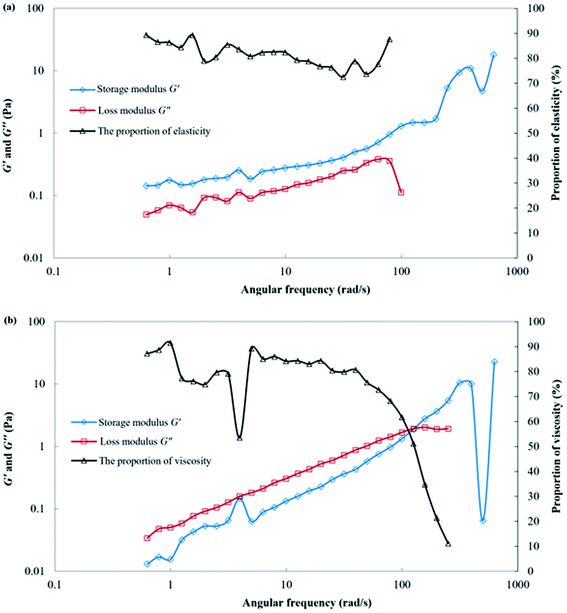
When the values of G′ and G′′ had been obtained, the values of Eels and Evis were then determined to evaluate the elastic and viscous properties for the polymer gelant and the SGC gelant.
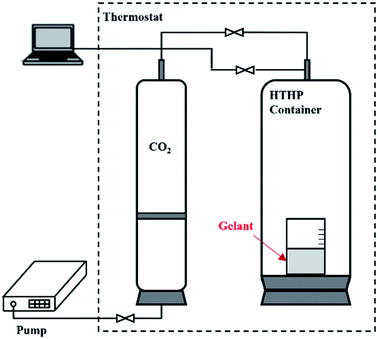
After the viscosity and rheology had been determined, the polymer gelant and the SGC gelant were placed in a container for 24 h for the gelation process to occur. The container was resistant to CO2 corrosion, and could hold a high-temperature and high-pressure (HTHP) condition as shown in Fig. 1. The temperature was set at 65 °C, and the pressure was maintained as 15 MPa by CO2 (with a purity of 99.99 mol%). After the gelation, the viscosities of the polymer gel and the SGC gel were again measured using the viscometer, and the G′ and G′′ values of the gels were also determined using the rheometer.
2.2 The 1D injectivity and plugging experiments of the polymer gel and the SGC gel
The injectivity and plugging performance of the polymer gel and the SGC gel were then studied using 1D sand packs. The sand packs with an average permeability of 8000 × 10−3 μm2 were utilized to simulate the high permeable water channels, and the diameter of the sand pack was 25 mm, and was the length is 1000 mm, and the other physical parameters of the sand packs are listed in Table 1. The formation water and chemical agents used in the 1D experiments were the same as mentioned previously.| Gel type | Gelant injection volume/PV | Permeability/×10−3 μm2 | Porosity/% |
|---|---|---|---|
| Polymer gel | 0.025 | 8208 | 40.75 |
| 0.05 | 8461 | 41.54 | |
| 0.075 | 8737 | 42.63 | |
| 0.10 | 7463 | 37.99 | |
| 0.15 | 8260 | 41.06 | |
| SGC gel | 0.01 | 7694 | 39.89 |
| 0.02 | 8152 | 40.67 | |
| 0.03 | 7509 | 38.29 | |
| 0.05 | 7153 | 36.99 | |
| 0.075 | 8633 | 42.11 | |
| 0.10 | 7985 | 40.09 |
The core was firstly vacuumed and then saturated with formation water. The experimental temperature was set to 65 °C, and then a primary waterflooding process was conducted with a constant injection rate of 0.3 mL min−1. When the waterflooding pressure reached a steady state, the gelant was injected until a certain volume was reached. After 24 h of gelation, another waterflooding process was again conducted with the same injection rate. When the volume of the second waterflooding water reached 2.0 PV, the experiment was terminated. During the experimental process, the primary waterflooding pressure (pwb), the gelant injection pressure (pgel), the water breakthrough pressure (pwB) and the second waterflooding pressure (pwa) can be obtained. Then, a resistance factor (RF) of gelant can be calculated using the waterflooding pressure (pwb) and the gelant injection pressure (pgel) as shown in eqn (5). Because the RF was related to the pgel, it can be used to reflect the injectivity of the gelant:
 | (5) |
When the water breaks through the gel and maintains a steady state after 2.0 PV of injection, a residual resistance factor (RRF) can be calculated using the primary waterflooding pressure (pwb) and the second waterflooding pressure (pwa) as shown in eqn (6). Because the RRF was a comparison of water flow ability before and after gelation, it can be used to reflect the plugging performance of the gel:
 | (6) |
The injectivity and plugging performance of the polymer gel and the SGC gel were evaluated, and different injection volumes of the gelants were determined in the 1D sand packs. The injection volume ranged from 0.025 PV to 0.15 PV for the polymer gelant, and ranged from 0.01 PV to 0.10 PV for the SGC gelant. For each scenario, the experimental procedures were repeated as mentioned previously.
2.3 The 3D experiments for SGC gel assisted CO2 huff-n-puff
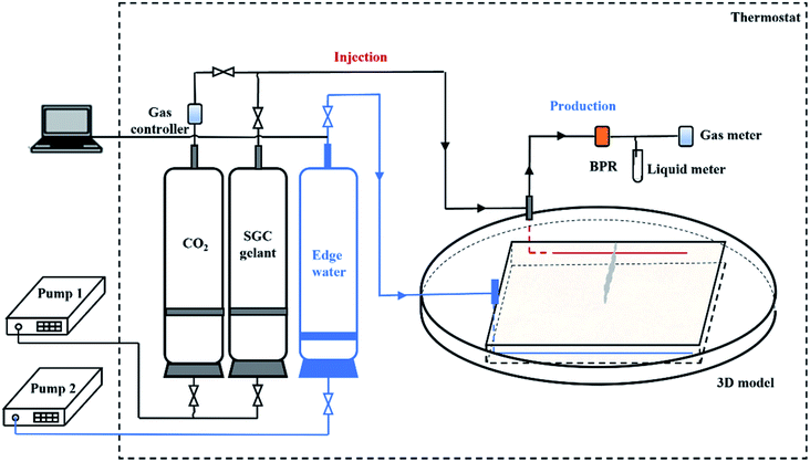
The 3D physical models were designed in the laboratory to study the EOR mechanisms of the SGC gel assisted CO2 huff-n-puff. The size of the model was 300 × 300 × 45 mm3 with a matrix permeability (Km) of 500 × 10−3 μm2, and two horizontal wells were located on the opposite side of the model as shown in Fig. 2. Well P1 with a length of 280 mm was used for edge-water injection, and well P2 with a length of 200 mm was used as a producer. A water channel with a size of 150 × 25 × 45 mm3 was created which was orthogonal to P2 in the 3D model, and the permeability of the channel (Kc) was 8000 × 10−3 μm2. Four impermeable zones were fabricated beside the four sides of the model in order to fit the 3D core holder, and no fluids could be exchanged between the permeable and impermeable zones. The physical parameters of the 3D models are shown in Table 2. A 3D core holder was specially designed for the HTHP displacement experiments with an operational temperature of 0–120 °C and an operational pressure of 0–30 MPa (as shown in Fig. 2(b)). The formation water, CO2 and chemical agents used in the 3D experiments were the same as mentioned previously. The formation oil was collected from the reservoir block. The density of the formation oil was 0.89 g cm−3, the viscosity was 58.21 mPa s, and the gas/oil ratio was 42.42 m3 m−3 under formation conditions (65 °C, 15 MPa).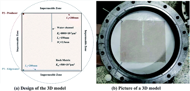 | ||
| Fig. 2 A 3D physical model for SGC gel assisted CO2 huff-n-puff. (a) Design of the 3D model (b) picture of a 3D model. | ||
| No. | Experimental scheme | Apparent volume/mL | Pore volume/mL | Porosity/% | Permeability/×10−3 μm2 | Initial oil saturation/% |
|---|---|---|---|---|---|---|
| a Where Km is the permeability of the matrix (×10−3 μm2), and Kc is the permeability of the water channel ×10−3 μm2). | ||||||
| 1 | CO2 huff-n-puff | 4032 | 1054 | 26.14 | Km = 500 | 59.14 |
| 2 | SGC gel assisted | 4036 | 1047 | 25.94 | Kc = 8000 | 58.76 |
| CO2 huff-n-puff | ||||||
Fig. 3 shows the flow chart for the 3D experiments using gel assisted CO2 huff-n-puff. The experimental setup consisted of six sub-systems: an injection system, an edge-water injection system, a displacement system, a production system, a temperature control system, and a data acquisition system. In the injection system, CO2 and SGC gelant were stored in transfer cylinders and then injected into the model by a constant pressure and rate pump. In the edge-water injection system, formation water was stored in the cylinder and then injected into the model through P1. The 3D physical model was placed in the core holder with a confining pressure. In the production system, a backpressure regulator (BPR) was connected with P2 to control the production pressure. The produced oil and water were collected in test tubes and the volumes were measured, and the gas was measured using a gas flow meter. The thermostat was used to maintain the experimental temperature, and the displacement pressures of P1 and P2 were obtained by the data acquisition system. The physical parameters of the 3D models are listed in Table 2. An experiment using a pure CO2 huff-n-puff system was also conducted for comparison.
Scenario 1 was utilized for the CO2 huff-n-puff experiment, and the experimental procedure was as follows: (1) the 3D model was held by the core holder, and then placed into the thermostat at a temperature of 65 °C. The production pressure of P2 was set to 15 MPa to maintain the formation pressure. Then, the formation water and oil were injected into the model to form the initial oil and water saturation. (2) The water was injected through P1 with an injection rate of 0.5 mL min−1 to simulate edge-water driving. After the water cut of P2 reached 98%, the edge-water driving process was terminated. (3) The CO2 was injected into the model through P2 until the pressure reaches 20 MPa. After 24 h of soaking time, P1 and P2 were reopened for production. When the water cut of P2 reached 98% again, one cycle of CO2 huff-n-puff was completed. The injection of gas, the production of oil, water and gas, and the displacement pressure were recorded during the experimental process. (4) Three more cycles of CO2 huff-n-puff processes were conducted using the 3D model, and the oil recovery of edge-water driving and CO2 huff-n-puff were calculated after the experiment.
Scenario 2 was utilized for the SGC gel assisted CO2 huff-n-puff experiment. The experimental processes of preparation and edge-water driving were the same as for Scenario 1, whereas the procedures of gel assisted CO2 huff-n-puff were as follows: (1) firstly, P2 was opened as a production well to ensure that the gelant can be injected into the model, then 5 mL of SGC gelant was injected through P1. P1 and P2 were then closed for 24 h to allow the gelation process to occur. (2) The CO2 was injected into the model through P1 until the pressure reached 20 MPa. P1 and P2 were then reopened for production after a soaking time of 24 h. When the water cut of P2 reached 98% again, one cycle of gel assisted CO2 huff-n-puff was completed. (3) Three more cycles of gel assisted CO2 huff-n-puff processes were conducted on the 3D model, and the oil recovery enhanced by SGC gel assisted CO2 huff-n-puff was calculated after the experiment.
3. Results and discussion
3.1 Performance comparisons of SGC gel and polymer gel
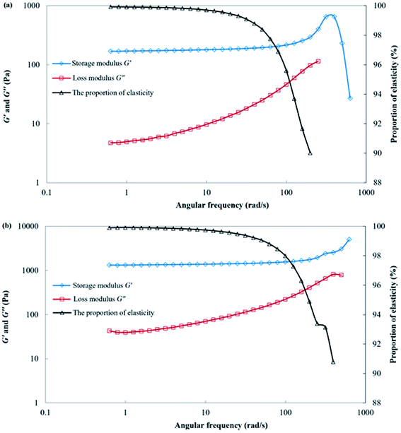
After 24 h of gelation, both the polymer gelant and the SGC gelant can form solid-like gels. The viscosity of the polymer gel was 22![[thin space (1/6-em)]](https://www.rsc.org/images/entities/char_2009.gif) 558 mPa s, whereas the viscosity of the SGC gel was as high as 174
558 mPa s, whereas the viscosity of the SGC gel was as high as 174![[thin space (1/6-em)]](https://www.rsc.org/images/entities/char_2009.gif) 267 mPa s. The rheological behaviors of the polymer gel and the SGC gel are shown in Fig. 5. For these two gels, the storage modulus G′ was significantly higher than the loss modulus G′′, and the proportion of the elastic property (Eela) was more than 99% at low frequencies. As a result, both gels could form strong barriers for plugging within the porous media, and then force the successive water or gas to displace the upswept area for oil recovery. In addition, the G′ and G′′ of the SGC gel were also significantly higher than those of the polymer gel. The SGC gelant can form a higher strength gel when compared with that of the polymer gelant, which showed it had more potential for use in applications for channeling treatments during the CO2 huff-n-puff process.
267 mPa s. The rheological behaviors of the polymer gel and the SGC gel are shown in Fig. 5. For these two gels, the storage modulus G′ was significantly higher than the loss modulus G′′, and the proportion of the elastic property (Eela) was more than 99% at low frequencies. As a result, both gels could form strong barriers for plugging within the porous media, and then force the successive water or gas to displace the upswept area for oil recovery. In addition, the G′ and G′′ of the SGC gel were also significantly higher than those of the polymer gel. The SGC gelant can form a higher strength gel when compared with that of the polymer gelant, which showed it had more potential for use in applications for channeling treatments during the CO2 huff-n-puff process.
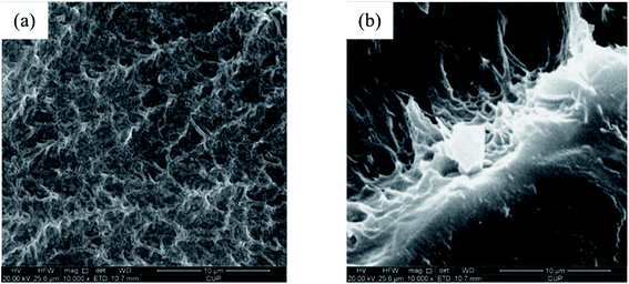
The microstructures of the polymer gel and the SGC gel were studied using SEM analysis, and the scanned images were compared and are shown in Fig. 6. For the polymer gel, the polymer chain was crosslinked with another chain, and then formed a continuous network structure.40 The skeleton structure of the gel constructed by crosslinked the molecules can be clearly observed from Fig. 6(a). However, the structure of the SGC gel could not be seen properly until the gel was destroyed artificially. The gel surface was smooth and flat, but its interior showed a tighter crosslinked structure (as shown in Fig. 6(b)). The α-starch molecules can function as rigid skeletons, and then the skeletons can be flexibly filled with the AM.45 After the crosslinking reactions, a more complex 3D network-like structure was formed, which had a higher strength when compared with the polymer gel.
| Gel type | Gel injection volume/PV | Waterflooding pressure (pwb)/kPa | Gelant injection pressure (pgel)/kPa | Successive waterflooding | |
|---|---|---|---|---|---|
| Breakthrough pressure (pwB)/kPa | Residual pressure (pwa)/kPa | ||||
| Polymer gel | 0.025 | 1.4 | 6.1 | 146.8 | 144.3 |
| 0.05 | 1.4 | 10.1 | 202 | 179.7 | |
| 0.075 | 1.3 | 13.8 | 229.6 | 192.8 | |
| 0.10 | 1.6 | 23.1 | 322.2 | 243.8 | |
| 0.15 | 1.4 | 33.1 | 385.6 | 229.8 | |
| SGC gel | 0.01 | 1.5 | 3.4 | 820.3 | 819.3 |
| 0.02 | 1.5 | 4.1 | 857.5 | 847.8 | |
| 0.03 | 1.6 | 5.6 | 943 | 935.6 | |
| 0.05 | 1.7 | 6.8 | 1047.6 | 1000.7 | |
| 0.075 | 1.4 | 8.9 | 925.7 | 849.4 | |
| 0.10 | 1.5 | 12.7 | 997.1 | 923 | |
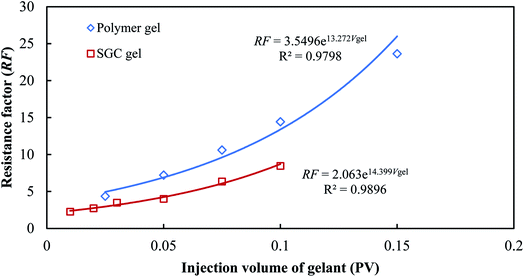
The different injectivity and plugging performances of the SGC gel and the polymer gel were determined using the resistance factors (RF) and the residual resistance factors (RRF). The resistance factor of the gelant retains an exponential growth with the injection volume for both the SGC gelant and the polymer gelant as shown in Fig. 7. From the fitting curves, an empirical formula can be obtained:
RF = a![[thin space (1/6-em)]](https://www.rsc.org/images/entities/char_2009.gif) exp(bVgel) exp(bVgel)
| (7) |
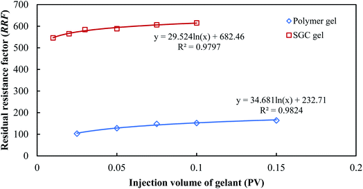
The RRF retains a logarithmic growth with the injection volume for both the SGC gelant and the polymer gelant as shown in Fig. 8, which can also be fitted as:
RRF = c![[thin space (1/6-em)]](https://www.rsc.org/images/entities/char_2009.gif) ln(Vgel) + d ln(Vgel) + d
| (8) |
3.2 The EOR mechanisms of the SGC gel assisted CO2 huff-n-puff
In order to study the EOR mechanisms of the SGC gel assisted CO2 huff-n-puff in a water channeling reservoir, 3D experiments were conducted in the laboratory and the results are shown in Table 4. A pure CO2 huff-n-puff experiment was conducted after edge-water driving in Scenario 1 for a comparison. The oil recovery of the edge-water driving was 33.90% when the water cut of the producer reached 98%. Then, four cycles of CO2 huff-n-puff processes were conducted with an average CO2 volume of 1255 mL (surface conditions) for each cycle. However, the oil recovery factors were only 1.28%, 1.19%, 0.99% and 0.98% for the 1st, 2nd, 3rd and 4th cycles, respectively. Due to the existence of the water channels, the edge-water mostly flowed through the channel, leaving plenty of formation oil, and the injected CO2 remained at the rock matrix. For the SGC gel assisted CO2 huff-n-puff experiment in Scenario 2, a similar remaining oil saturation was found with an oil recovery of 31.88% after the edge-water driving. Then, the SGC gel with a volume of 5 mL (calculated as 0.03 PV of the water channels) was first injected into the core, followed by a similar CO2 volume of 1239 mL for each cycle. After the channel was plugged, the oil recovery factor was enhanced to 3.89%, 3.61%, 2.13% and 1.73% for the 1st, 2nd, 3rd and 4th cycles, respectively. The total oil recovery enhanced by gel assisted CO2 huff-n-puff was 11.36%, which was 2.56 times higher than that of the pure CO2 huff-n-puff process. Fig. 9(a) compares the water cuts of the pure CO2 huff-n-puff, and gel assisted CO2 huff-n-puff processes. For the pure CO2 huff-n-puff experiment, the water cut firstly dropped to 91–93% at the initial production stage, and then increased sharply to about 96% when the edge-water broke through along the channel. After an average 0.24 PV of valid production time, the water cut reached 98% again. For the gel assisted CO2 huff-n-puff experiment, the water cut dropped drastically to 4–18% at the initial stage, and an amount of crude oil was produced together with CO2. Then, the water cut gradually increased to more than 90% with the driving of the edge water. The valid production time could also be greatly prolonged to 0.26–0.50 PV, which was about 1.6 times higher than that of the pure CO2 huff-n-puff.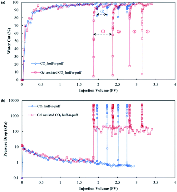 | ||
| Fig. 9 Production performances of pure CO2 huff-n-puff and gel assisted CO2 huff-n-puff processes: (a) water cut comparison and (b) pressure drop comparison. | ||
| No. | Period | Cycle no. | SGC gel volume/mL | CO2 volume (surface)/mL | Production oil volume/mL | Oil recovery factor/% | Lowest water cut/% | Valid production time /PV |
|---|---|---|---|---|---|---|---|---|
| 1 | Edgewater driving | — | — | — | 211.38 | 33.90 | — | 1.96 |
| CO2 huff-n-puff | 1st | — | 1279 | 7.99 | 1.28 | 92.85 | 0.26 | |
| 2nd | — | 1262 | 7.39 | 1.19 | 92.37 | 0.23 | ||
| 3rd | — | 1236 | 6.20 | 0.99 | 91.67 | 0.23 | ||
| 4th | — | 1244 | 6.09 | 0.98 | 91.23 | 0.23 | ||
| Total | — | — | 5021 | 239.05 | 38.34 | — | 2.91 | |
| 2 | Edge water driving | — | — | — | 196.15 | 31.88 | — | 1.87 |
| SGC gel assisted | 1st | 5 | 1262 | 23.95 | 3.89 | 4.41 | 0.50 | |
| CO2 huff-n-puff | 2nd | 5 | 1239 | 22.24 | 3.61 | 5.79 | 0.44 | |
| 3rd | 5 | 1205 | 13.13 | 2.13 | 17.58 | 0.33 | ||
| 4th | 5 | 1234 | 10.63 | 1.73 | 7.37 | 0.26 | ||
| Total | — | 20 | 4940 | 266.10 | 43.24 | — | 3.40 |
Fig. 9(b) compares the pressure drops of the pure CO2 huff-n-puff and gel assisted CO2 huff-n-puff. Similar pressure drops of about 1.5 kPa were observed during the edge-water driving periods for these two experiments, however, the drops show greater differences during the huff-n-puff period. For the pure CO2 huff-n-puff experiment, the pressure drop decreased instantaneously from 5 MPa to less than 1 kPa at the initial stage of production. The edge-water broke through immediately along the channel, but the formation oil and injected CO2 still remained within the rock matrix and could not be produced after water channeling. For the gel assisted CO2 huff-n-puff experiment, the pressure drop gradually decreased from 5 MPa to about 500 kPa at the initial stage, where the oil was produced together with CO2. Then, the pressure drop remained at a level of about 150 kPa until the end of the production stage, which was a hundred times greater than that of pure CO2 huff-n-puff. After the successful plugging of the water channels using SGC gel, the remaining oil of the near-wellbore area was extracted by the injected CO2 first, and the oil of the deep formation was then effectively displaced to the production well by the edge water, which showed that the injection of the gel enlarged the sweep efficiency of both CO2 and the edge water.49,50 The oil recovered from both the near-wellbore area and the deep formation showed that a remarkable oil enhancement had been achieved. The 3D experimental results showed that the SGC gel has great potential for assisting the CO2 huff-n-puff for further enhanced oil recovery in the water channeling reservoir.
3.3 Pilot tests of the SGC gel assisted CO2 huff-n-puff process
Several pilot tests of the SGC gel assisted CO2 huff-n-puff process have been conducted in the North Gaoqian Block, Jidong Oilfield, China since 2016, and the results of five wells are shown in Table 5. Before the gel assisted CO2 huff-n-puff operations, all the wells were facing severe water channeling problems with water cuts of more than 99%. Then, 320–850 m3 of the gels were firstly injected into the wells for water channeling treatments, followed by CO2 injection with an average volume of 22![[thin space (1/6-em)]](https://www.rsc.org/images/entities/char_2009.gif) 666 m3. After the wells were reopened for production, remarkable water control effects were obtained with the water cuts reaching as low as 10.4–65.6%. The valid production time of gel assisted CO2 huff-n-puff ranged from 181 d to 401 d, and an average oil production of 542 m3 was recovered by the gel assisted CO2 huff-n-puff process during each cycle.
666 m3. After the wells were reopened for production, remarkable water control effects were obtained with the water cuts reaching as low as 10.4–65.6%. The valid production time of gel assisted CO2 huff-n-puff ranged from 181 d to 401 d, and an average oil production of 542 m3 was recovered by the gel assisted CO2 huff-n-puff process during each cycle.
| Well no. | Cycle | Operation period | Gel volume/m3 | CO2 volume/m3 | Oil production/m3 | Lowest water cut/% | Valid production time/day |
|---|---|---|---|---|---|---|---|
| G104-5CP13 | 1st | 2017.01–2017.11 | 320 | 21![[thin space (1/6-em)]](https://www.rsc.org/images/entities/char_2009.gif) 551 551 |
508.70 | 46.8 | 221 |
| 2nd | 2018.03–2019.03 | 400 | 22![[thin space (1/6-em)]](https://www.rsc.org/images/entities/char_2009.gif) 727 727 |
632.90 | 51.5 | 326 | |
| G104-5P8 | 1st | 2020.02–2020.09 | 450 | 19![[thin space (1/6-em)]](https://www.rsc.org/images/entities/char_2009.gif) 305 305 |
382.39 | 40.0 | 181 |
| G104-5P42 | 1st | 2016.08–2017.07 | 850 | 24![[thin space (1/6-em)]](https://www.rsc.org/images/entities/char_2009.gif) 385 385 |
310.16 | 65.6 | 237 |
| 2nd | 2017.07–2018.03 | 800 | 21![[thin space (1/6-em)]](https://www.rsc.org/images/entities/char_2009.gif) 444 444 |
241.71 | 65.0 | 188 | |
| G104-5P60 | 1st | 2020.03–2021.05 | 500 | 25![[thin space (1/6-em)]](https://www.rsc.org/images/entities/char_2009.gif) 134 134 |
780.20 | 39.6 | 401 |
| G207-4 | 1st | 2018.08–2020.05 | 650 | 24![[thin space (1/6-em)]](https://www.rsc.org/images/entities/char_2009.gif) 118 118 |
934.80 | 10.4 | 320 |
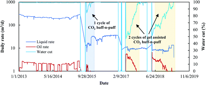
It was found that two cycles of the gel assisted CO2 huff-n-puff process had been operated in the G104-5CP13 and G104-5P42 oil wells between 2017 and 2019. Taking G104-5CP13 as an example, its production performance since 2013 is shown in Fig. 10. This well faced the water channeling problem for more than five years with the water cut as high as 99%. One cycle of the huff-n-puff process with a CO2 volume of 19![[thin space (1/6-em)]](https://www.rsc.org/images/entities/char_2009.gif) 251 m3 was conducted between 2015.07 and 2015.12, however, only 73.54 m3 of oil was recovered by pure CO2, and the water cut dropped to 85.5% and then increased rapidly to 99% again within 113 d. However, for the gel assisted CO2 huff-n-puff, the water cut could drop to as low as 46.8%, and the valid production time could be prolonged to more than 200 d, and more than 500 m3 of crude oil was recovered in the following two cycles. In addition, the oil rate could also be enhanced to more than 5.5 m3 per day at the initial stage of the gel assisted CO2 huff-n-puff, which was more than 3.5 times higher than those of edge-water driving and the pure CO2 huff-n-puff process.
251 m3 was conducted between 2015.07 and 2015.12, however, only 73.54 m3 of oil was recovered by pure CO2, and the water cut dropped to 85.5% and then increased rapidly to 99% again within 113 d. However, for the gel assisted CO2 huff-n-puff, the water cut could drop to as low as 46.8%, and the valid production time could be prolonged to more than 200 d, and more than 500 m3 of crude oil was recovered in the following two cycles. In addition, the oil rate could also be enhanced to more than 5.5 m3 per day at the initial stage of the gel assisted CO2 huff-n-puff, which was more than 3.5 times higher than those of edge-water driving and the pure CO2 huff-n-puff process.
A total gel volume of 3970 m3 was used for water channeling treatments in these eight wells, and the cumulative CO2 volume reached 15.87 × 10⁴ m3. A cumulative oil production of 3790.86 m3 was obtained by the end of 2020, which showed that the gel assisted CO2 huff-n-puff had economic benefits in the water channeling reservoir.
4. Conclusions
Gel assisted CO2 huff-n-puff can be used for further enhanced oil recovery in a water channeling reservoir. The starch graft copolymer (SGC) gel is selected for the assisted process due to its better performances after a comparison with the polymer gel. Then, laboratory experiments and pilot tests of the SGC gel assisted CO2 huff-n-puff were conducted to enhance oil recovery, and some of the conclusions obtained are summarized as follows:(1) Although the bulk viscosities of the polymer gelant and the SGC gelant were similar, their rheological performances are quite different. The polymer gelant is a predominantly elastic solution, whereas the SGC gelant is a predominantly viscous solution, which makes it easier to inject it into the pore throats. The RF value of the SGC gelant is only 0.58 times greater than that of the polymer gelant, which shows that the SGC gelant has a better injectivity when compared with the polymer gelant.
(2) Both the polymer gelant and the SGC gelant can form solid-like gels, however, the strength of the SGC gel is much higher, with a viscosity of 174![[thin space (1/6-em)]](https://www.rsc.org/images/entities/char_2009.gif) 267 mPa s. The results of the SEM analysis revealed that a more complex 3D network-like structure was formed using SGC gelant, and the RRF value of the SGC gel was about three times higher than that of the polymer gel. The higher strength of the SGC gel guarantees that a stronger barrier is formed within the high permeable water channels.
267 mPa s. The results of the SEM analysis revealed that a more complex 3D network-like structure was formed using SGC gelant, and the RRF value of the SGC gel was about three times higher than that of the polymer gel. The higher strength of the SGC gel guarantees that a stronger barrier is formed within the high permeable water channels.
(3) The SGC gel assisted CO2 huff-n-puff and pure CO2 huff-n-puff are compared using 3D experiments, and the results show that four cycles of gel assisted CO2 huff-n-puff achieve an oil recovery enhancement of 11.36%, which is 2.56 times greater than that using pure CO2 huff-n-puff. For the gel assisted CO2 huff-n-puff process, the water cut can drop to as low as 4–18%, the pressure drop gradually decreases and then remains at a level of about 150 kPa, and the valid production time can be prolonged to about 1.6 times greater than that of the pure CO2 huff-n-puff process.
(4) After the channel is plugged by the SGC gel, the remaining oil of the near-wellbore area can be first extracted by CO2, and the oil of the deep formation can then be effectively displaced by the edge water. With the combination of CO2 extraction and edge-water driving, the oil remaining in rock matrix can be remarkably improved using the gel assisted CO2 huff-n-puff process.
(5) Several pilot tests of the gel assisted CO2 huff-n-puff process have been conducted in the North Gaoqian Block, Jidong Oilfield, China since 2016. With a total gel volume of 3970 m3 assisted with 15.87 × 10⁴ m3 of CO2 used in five wells, a cumulative oil production of 3790.86 m3 was obtained by the end of 2020. From the pilot tests, it was found that gel assisted CO2 huff-n-puff gave economic benefits, which can provide guidance for further enhanced oil recovery in similar oil reservoirs.
Conflicts of interest
The authors declare that there are no competing interests regarding the publication of this article.Acknowledgements
This project is supported by the National Natural Science Foundation of China (Grant No. 52174046). The authors wish to acknowledge all their colleagues from Changzhou University, China University of Petroleum (Beijing), Exploration and Development Research Institute, PetroChina Daqing Oilfield Company, and the Drilling and Production Technology Research Institute of the PetroChina Jidong Oilfield Company, who all helped with this research.References
- S. Xu, Q. Feng, F. Guo, A. Yan, S. Liu, Y. Tao and X. Chen. Efficient development method for high-viscosity, complex Fault-block reservoir. SPE Trinidad and Tobago Section Energy Resources Conference, Port of Spain, Trinidad and Tobago, 2016 Search PubMed.
- Q. Yu, Z. Mu, P. Liu, X. Hu and Y. Li, A new evaluation method for determining reservoir parameters for the development of edge-water-driven oil reservoirs, J. Pet. Sci. Eng., 2019, 175, 255–265 CrossRef CAS.
- Z. Pang, Y. Jiang, B. Wang, G. Cheng and X. Yu, Experiments and analysis on development methods for horizontal well cyclic steam stimulation in heavy oil reservoir with edge water, J. Pet. Sci. Eng., 2020, 188, 106948 CrossRef CAS.
- Q. Feng, S. Li, Y. Su, Y. Liu and X. Han. Analyzing edge water drive laws of offshore heavy oil reservoir with physical experiment and numerical simulation. SPE Energy Resources Conference, Port of Spain, Trinidad and Tobago, 2014 Search PubMed.
- R. Cui, Q. Feng, Z. Li, F. Guo, A. Yan, S. Liu, Y. Tao and X. Chen. Improved oil recovery for the complex fault-block and multilayered reservoir with edge water. SPE Trinidad and Tobago Section Energy Resources Conference, Port of Spain, Trinidad and Tobago, 2016 Search PubMed.
- S. Seyyedsar, S. Farzaneh and M. Sohrabi, Experimental investigation of tertiary CO2 injection for enhanced heavy oil recovery, J. Nat. Gas Sci. Eng., 2016, 34, 1205–1214 CrossRef CAS.
- A. Ahadi and F. Torrabi, Effect of light hydrocarbon solvents on the performance of CO2-based cyclic solvent injection (CSI) in heavy oil systems, J. Pet. Sci. Eng., 2018, 163, 526–537 CrossRef CAS.
- A. Lobanov, K. Shhekoldin, I. Struchkov, M. Zvonkov, M. Hlan, E. Pustova, V. Kovalenko and A. Zolotukhin, Swelling/extraction test of Russian reservoir heavy oil by liquid carbon dioxide, Petrol. Explor. Dev., 2018, 45(5), 918–926 CrossRef.
- X. Zhou, X. Li, D. Shen, L. Shi and Q. Jiang, CO2 huff-n-puff process to enhance heavy oil recovery and CO2 storage: An integration study, Energy, 2022, 239, 122003 CrossRef CAS.
- C. Tian, Z. Pang, D. Liu, X. Wang, Q. Hong, J. Chen, Y. Zhang and H. Wang, Micro-action mechanism and macro-prediction analysis in the process of CO2 huff-n-puff in ultra-heavy oil reservoirs, J. Pet. Sci. Eng., 2022, 211, 110171 CrossRef CAS.
- S. Talebian, R. Masoudi, I. Tan and P. Zitha, Foam assisted CO2-EOR: A review of concept, challenges, and future prospects, J. Pet. Sci. Eng., 2014, 120, 202–215 CrossRef CAS.
- B. Iraji, S. Shadizadeh and M. Riazi, Experimental investigation of CO2 huff and puff in a matrix-fracture system, Fuel, 2015, 158, 105–112 CrossRef CAS.
- J. Tetteh and R. Barati. Wettability alteration and enhanced oil recovery using low salinity waterflooding in limestone rocks: A mechanistic study. SPE Kingdom of Saudi Arabia Annual Technical Symposium and Exhibition, Dammam, Saudi Arabia, 2018 Search PubMed.
- A. Katende and F. Sagala, A critical review of low salinity water flooding: Mechanism, laboratory and field application, J. Mol. Liq., 2019, 278, 627–649 CrossRef CAS.
- J. Song, Q. Wang, I. Shaik, M. Puerto and G. Hirasaki, Effect of salinity, Mg2+ and SO42- on ‘‘smart water”-induced carbonate wettability alteration in a model oil system, J. Colloid Interface Sci., 2020, 563, 145–155 CrossRef CAS PubMed.
- J. Sheng, A comprehensive review of alkaline-surfactant-polymer (ASP) flooding, Asia-Pac. J. Chem. Eng., 2014, 9, 471–489 CAS.
- R. Pogaku, N. Fuat, S. Sakar, Z. Cha, N. Musa, D. Tajudin and L. Morris, Polymer flooding and its combinations with other chemical injection methods in enhanced oil recovery, Polym. Bull., 2018, 75(4), 1753–1774 CrossRef CAS.
- L. Hedraningrat and O. Torsæter, Metal oxide-based nanoparticles: revealing their potential to enhance oil recovery in different wettability systems, Appl. Nanosci., 2015, 5, 181–199 CrossRef.
- Y. Kazemzadeh, M. Sharifi, M. Riazi, H. Rezvani and M. Tabaei, Potential effects of metal oxide/SiO2 nanocomposites in EOR processes at different pressures, Colloids Surf., A, 2018, 559, 372–384 CrossRef CAS.
- M. Qu, T. Liang, J. Hou, Z. Liu, E. Yang and X. Liu, Laboratory study and field application of amphiphilic molybdenum disulfide nanosheets for enhanced oil recovery, J. Pet. Sci. Eng., 2022, 208, 109695 CrossRef CAS.
- M. Qu, T. Liang, L. Xiao, J. Hou, P. Qi, Y. Zhao, C. Song and J. Li, Mechanism study of spontaneous imbibition with lower-phase nano-emulsion in tight reservoirs, J. Pet. Sci. Eng., 2022, 211, 110220 CrossRef CAS.
- N. Anuar, M. Yunan, F. Sagala and A. Katende, The effect of WAG ratio and oil density on oil recovery by immiscible water alternating gas flooding, American Journal of Science and Technology, 2017, 4(5), 80–90 Search PubMed.
- L. Wang, Y. He, Q. Wang, M. Liu and X. Jin, Multiphase flow characteristics and EOR mechanism of immiscible CO2 water-alternating-gas injection after continuous CO2 injection: A micro-scale visual investigation, Fuel, 2020, 282, 118689 CrossRef CAS.
- K. Jessen, G. Tang and A. Kovscek, Laboratory and simulation investigation of enhanced coalbed methane recovery by gas injection, Transp. Porous Media, 2008, 73, 141–159 CrossRef CAS.
- H. Hao, J. Hou, F. Zhao, H. Huang and P. Wang, Laboratory investigation of cyclic gas injection using CO2/N2 mixture to enhance heavy oil recovery in a pressure-depleted reservoir, Arabian J. Geosci., 2020, 13, 140 CrossRef CAS.
- F. Torabi, A. Kavousi, F. Qazvini and C. Chan, The feasibility of lab-scale cyclic CO2 injection in fractured porous media, Liq. Fuels Technol., 2014, 32(7), 797–803 CAS.
- K. Zhang, S. Li and L. Liu, Optimized foam-assisted CO2 enhanced oil recovery technology in tight oil reservoirs, Fuel, 2020, 267, 117099 CrossRef CAS.
- J. Solbakken and M. Aarra, CO2 mobility control improvement using N2-foam at high pressure and high temperature conditions, Int. J. Greenh. Gas Control, 2021, 109, 103392 CrossRef CAS.
- R. Sydansk. A new conformance-improvement-treatment chromium(III) gel technology. SPE enhanced oil recovery symposium. Tulsa, Oklahoma, USA, 1988 Search PubMed.
- B. Sengupta, V. Sharma and G. Udayabhanu, Gelation studies of an organically crosslinked polyacrylamide water shut-off gel system at different temperatures and pH, J. Pet. Sci. Eng., 2012, 81, 145–150 CrossRef CAS.
- G. Zhao, C. Dai, A. Chen, Z. Yan and M. Zhao, Experimental study and application of gels formed by nonionic polyacrylamide and phenolic resin for in-depth profile control, J. Pet. Sci. Eng., 2015, 135, 552–560 CrossRef CAS.
- C. Zareie, A. Bahramian, M. Sefti and M. Salehi, Network-gel strength relationship and performance improvement of polyacrylamide hydrogel using nano-silica; with regards to application in oil wells conditions, J. Mol. Liq., 2019, 278, 512–520 CrossRef CAS.
- S. Asadizadeh, S. Ayatollahi and B. ZareNezhad, Fabrication of a highly efficient new nanocomposite polymer gel for controlling the excess water production in petroleum reservoirs and increasing the performance of enhanced oil recovery processes, Chin. J. Chem. Eng., 2021, 32, 385–392 CrossRef CAS.
- X. Sun, B. Bai, Y. Long and Z. Wang, A comprehensive review of hydrogel performance under CO2 conditions for conformance control, J. Pet. Sci. Eng., 2020, 185, 106662 CrossRef CAS.
- F. Jin, L. Yang, X. Li, S. Song and D. Du, Migration and plugging characteristics of polymer microsphere and EOR potential in produced-water reinjection of offshore heavy oil reservoirs, Chem. Eng. Res. Des., 2021, 172, 291–301 CrossRef CAS.
- D. Bal, S. Patra and S. Ganguly, Effectiveness of foam-gel formulation in homogenizing the CO2 front during subsurface sequestration, J. Nat. Gas Sci. Eng., 2015, 27, 994–1004 CrossRef CAS.
- Y. Zhang, M. Gao, Q. You, H. Fan, W. Li, Y. Liu, J. Fang, G. Zhao, Z. Jin and C. Dai, Smart mobility control agent for enhanced oil recovery during CO2 flooding in ultra-low permeability reservoirs, Fuel, 2019, 241, 442–450 CrossRef CAS.
- B. Zhou, W. Kang, H. Yang, Z. Li and B. Sarsenbekuly, The shear stability mechanism of cyclodextrin polymer and amphiphilic polymer inclusion gels, J. Mol. Liq., 2021, 328, 115399 CrossRef CAS.
- R. Singh and V. Mahto, Synthesis, characterization and evaluation of polyacrylamide graft starch/clay nanocomposite hydrogel system for enhanced oil recovery, Petrol. Sci., 2017, 14(4), 765–779 CrossRef CAS.
- D. Zhu, B. Bai and J. Hou, Polymer gel systems for water management in high temperature petroleum reservoirs: a chemical review, Energy Fuels, 2017, 31(12), 13063–13087 CrossRef CAS.
- Z. Song, J. Hou, X. Liu, Q. Wei, H. Hao and L. Zhang, Conformance control for CO2-EOR in naturally fractured low permeability oil reservoirs, J. Pet. Sci. Eng., 2018, 166, 225–234 CrossRef CAS.
- F. Zhao, P. Wang, S. Huang, H. Hao and G. Lu, Performance and applicable limits of multi-stage gas channeling control system for CO2 flooding in ultra-low permeability reservoirs, J. Pet. Sci. Eng., 2020, 192, 107336 CrossRef CAS.
- H. Hao, J. Hou, F. Zhao, Z. Song, L. Hou and Z. Wang, Gas channeling control during CO2 immiscible flooding in 3D radial flow model with complex fractures and heterogeneity, J. Pet. Sci. Eng., 2016, 146, 890–901 CrossRef CAS.
- H. Jia, H. Chen and J. Zhao, Development of a highly elastic composite gel through novel intercalated crosslinking method for wellbore temporary plugging in high-temperature reservoirs, SPE J., 2020, 25(6), 2853–2866 CrossRef CAS.
- Q. Luo, K. Tang, L. Bai, K. Li, P. Sun, C. Xu, Y. Zhao and D. Zhu, Development of in-situ starch grafted copolymerized gels for conglomerate reservoir conformance control and oil recovery improvement, J. Pet. Sci. Eng., 2022, 210, 110005 CrossRef CAS.
- U. Alfazazi, N. Thomas, W. Alameri and E. Al-Shalabi, Experimental investigation of polymer injectivity and retention under harsh carbonate reservoir conditions, J. Pet. Sci. Eng., 2020, 192, 107262 CrossRef CAS.
- J. Liu, L. Zhong, C. Wang, S. Li, X. Yuan, Y. Liu, X. Meng, J. Zou and Q. Wang, Investigation of a high temperature gel system for application in saline oil and gas reservoirs for profile modification. Journal of Petroleum Science and Engineering, J. Pet. Sci. Eng., 2020, 195, 107852 CrossRef CAS.
- S. Zhang, B. Peng and D. Luo, Formula optimization of thermosensitive biological sol–gel carrier for EOR surfactants by rheological investigation, J. Pet. Sci. Eng., 2021, 205, 108740 CrossRef CAS.
- S. Kumar and A. Mandal, A comprehensive review on chemically enhanced water alternating gas/CO2 (CEWAG) injection for enhanced oil recovery, J. Pet. Sci. Eng., 2017, 157, 696–715 CrossRef CAS.
- P. Guo, Z. Tian, R. Zhou, F. Chen, J. Du, Z. Wang and S. Hu, Chemical water shutoff agents and their plugging mechanism for gas reservoirs: A review and prospects, J. Nat. Gas Sci. Eng., 2022, 104, 104658 CrossRef.
| This journal is © The Royal Society of Chemistry 2022 |

