
 Open Access Article
 This Open Access Article is licensed under a Creative Commons Attribution-Non Commercial 3.0 Unported Licence
Solid oxide fuel cell with a spin-coated yttria stabilized zirconia/gadolinia doped ceria bi-layer electrolyte
Jingyu Liab,
Lijun Fanab,
Nianjun Houab,
Yicheng Zhao *ab and
Yongdan Liabc
*ab and
Yongdan Liabc
aState Key Laboratory of Chemical Engineering (Tianjin University), Tianjin Key Laboratory of Applied Catalysis Science and Technology, School of Chemical Engineering and Technology, Tianjin University, Tianjin, 300072, China. E-mail: zhaoyicheng@tju.edu.cn
bCollaborative Innovation Center of Chemical Science and Engineering (Tianjin), Tianjin, 300072, China
cDepartment of Chemical and Metallurgical Engineering, Aalto University, Kemistintie 1, FI-00076 Aalto, Finland
First published on 3rd May 2022
Abstract
A thin yttria stabilized zirconia (YSZ)/gadolinia doped ceria (GDC) bi-layer membrane is fabricated through the slurry spin coating technique and used as an electrolyte of a solid oxide fuel cell with La0.6Sr0.4Co0.2Fe0.8O3−δ as the cathode. The viscosity of the YSZ slurry is controlled by adding ethanol in the terpineol solvent, which shows a negligible effect on the thickness but a remarkable influence on the porosity of the YSZ film. The thickness of the YSZ layer increases with the YSZ content in the slurry. The YSZ films are pre-sintered at various temperatures, and the one sintered at 1200 °C has a moderate interaction with the GDC slurry, forming a 10 μm-thick YSZ/GDC bilayer with a low porosity and a low ohmic resistance. The corresponding single cell shows a maximum power density of 1480 mW cm−2 at 750 °C.
1. Introduction
The solid oxide fuel cell (SOFC) with high energy conversion efficiency, fuel flexibility and low emissions is widely recognized as a promising power generation technology.1,2 The practical application of the SOFC is mainly hindered by its high operating temperature, which limits the selection of component materials, increases the cost and reduces the durability. The low oxygen ionic conductivity of the traditional yttria-stabilized zirconia (YSZ) electrolyte, about 0.13 S cm−1 at 1000 °C,3 is one of the main reasons for the high operating temperature, and electrolyte materials with a higher ionic conductivity, such as doped ceria,4,5 doped LaGaO3,6 Er0.4Bi1.6O3−δ,7 Sr0.55Na0.45SiO2.775,8,9 Na0.5Bi0.49Ti0.98Mg0.02O3−δ (ref. 10) and proton-conducting perovskite oxides,11,12 have been extensively explored over the past decades. Unfortunately, those substitutes usually suffer from high electronic conductivity or low stability under operating conditions. So far, YSZ is still the most commonly used electrolyte material in commercial SOFC systems.Reducing the thickness of YSZ electrolyte layer is one of the major strategies for lowering the working temperature and boosting the performance of SOFC. For SOFC operated below 750 °C, the thickness of YSZ layer should be generally less than 15 μm.13 In recent years, many deposition methods, such as pulsed laser deposition,14 atomic layer deposition,15 chemical vapor deposition16 and sputtering,17 have been used to fabricate thin YSZ films with high quality. However, the high cost of those processes limits their large-scale application.
As a fast and cost-effective technique, slurry spin coating has been widely used to prepare gas-tight oxide electrolyte films.18–20 Wang et al.21 fabricated a 10 μm-thick YSZ membrane on a NiO–YSZ anode support with slurry spin coating, and the maximum power density (Pmax) of the single cell reaches 2 W cm−2 at 800 °C. Chen et al.22 coated a 10 μm-thick anode functional layer (AFL) and a 5 μm-thick YSZ electrolyte membrane successively on a NiO–YSZ anode support, and the Pmax of the cell is 0.6 W cm−2 at 800 °C. Many parameters of the spin coating process, such as the viscosity and solid content of the slurry, the spinning speed and duration, number of coating cycles and the property of AFL, have important effect on the thickness and porosity of the electrolyte layer. A higher spinning speed generally results in a thinner and denser membrane.23,24 Kim et al.25 found that rising the binder content in the slurry leads to the increase of thickness and porosity of the electrolyte layer. Buchkremer and co-workers26,27 optimized the size of YSZ nanoparticles in the slurry. Nevertheless, the relationships among the component and the viscosity of the slurry and the morphology of the electrolyte membrane have not been revealed clearly. Moreover, in order to avoid the interaction between YSZ and traditional perovskite cathode materials such as La0.6Sr0.4Co0.2Fe0.8O3−δ (LSCF), a thin doped ceria interlayer is usually required, which, however, will react with YSZ during the sintering process and form an insulating Ce–Zr solid solution phase.28–30
In this work, YSZ/Ce0.9Gd0.1O2−δ (GDC) bi-layer electrolyte is prepared with the slurry spin coating method. The effects of the solvent composition and the YSZ content on the viscosity of the slurry and the morphology of the YSZ membrane are discussed. The YSZ film is pre-sintered at various temperatures before the coating of the GDC layer. The interaction between YSZ and GDC phases and its influence on the cell performance are investigated.
2. Experimental
2.1. Material preparation
GDC powder was prepared through a coprecipitation process with oxalic acid as the precipitant.31 LSCF powder was synthesized via a glycine–nitrate combustion approach.32 The LSCF and GDC powders were mixed at a weight ratio of 1![[thin space (1/6-em)]](https://www.rsc.org/images/entities/char_2009.gif) :1 through ball-milling to form the LSCF–GDC composite cathode.
:1 through ball-milling to form the LSCF–GDC composite cathode.
2.2. Single cell fabrication
NiO–YSZ composite anode support layer was prepared through a cold-press approach. NiO (Shanghai Aladdin Bio-Chem Technology Co., Ltd, 99%), YSZ (Shanghai Naiou Nano technology Co., Ltd, 99.9%, particle size: 50 nm) and starch at a weight ratio of 56:44:9 were ball-milled in ethanol for 12 h. After drying, the composite powder was pressed at 300 MPa into a pellet with a diameter of 15 mm, which was sintered in air at 1100 °C for 3 h. The thickness of the obtained anode support layer is about 650 μm.
NiO–YSZ anode functional layer (AFL) was prepared via a spin-coating method. NiO and YSZ powders were mixed at a weight ratio of 56:44 through ball-milling. Terpineol (Shanghai Meryer Chemical Technology Co., Ltd, 99%), ethyl cellulose (EC, Tianjin Yuanli Chemical Technology Co., Ltd, AR) and ethanol (Shanghai Titan Scientific Co., Ltd, AR) were mixed at a weight ratio of 62:3:35 to form an organic solvent. The NiO–YSZ composite powder was mixed with the solvent at a weight ratio of 1:5 to form the AFL slurry, which was spin-coated on the anode support at 1000 rpm for 30 s and subsequently at 10000 rpm for 60 s. Then the organics were removed at 420 °C in air for 1 h. The spin-coating procedure was repeated three times.
YSZ electrolyte layer was also fabricated by the spin-coating method. 1 wt% EC was dissolved in 99 wt% terpineol, which was then mixed with ethanol to form the solvent. The concentration of ethanol in the solvent was in the range of 25–55 wt%. Subsequently, YSZ powder was added in the solvent, followed by ball-milling for 12 h to form the YSZ electrolyte slurry. The content of YSZ in the slurry was in the range of 25–40 wt%. The spin-coating procedure of the YSZ layer was similar to that of the AFL, which was repeated twice. YSZ/GDC bi-layer electrolyte was also prepared. After the deposition of one YSZ layer, the pellet was pre-sintered at 1000–1300 °C for 4 h, and a GDC layer was spin-coated on the YSZ layer. For the GDC slurry, the concentration of ethanol in the solvent and the content of GDC in the slurry were both 25 wt%. After the spin-coating process of the electrolyte layers, the pellets were sintered in air at 1400 °C for 4 h to form half cells.
The LSCF–GDC composite cathode powder was mixed with a binder (V006, Heraeus Ltd) to form the cathode slurry. The slurry was screen-printed on the electrolyte layer and sintered at 950 °C for 3 h. The geometrical area of the cathode was 0.28 cm2. Ag paste was coated on the electrodes as the current collector.
2.3. Characterization
The crystal structures of the GDC and LSCF powders were investigated at room temperature using an X-ray diffractometer (XRD, D8 Focus, Bruker Cor., Germany) with Cu-Kα radiation, 40 kV and 200 mA, at a scanning rate of 8° min−1. The morphology of the components of the single cell was observed with a scanning electron microscope (SEM, Apreo S LoVac, FEI, USA). The viscosity of the slurry for spin-coating was measured with a viscosimeter (NDJ-79, Shanghai Ni Run Intelligent Technology Co., Ltd, China).2.4. Electrochemical property
The current–voltage (I–V) curve of the single cell was measured with an electrochemical workstation (VersaSTAT 3, Ametek, USA) with H2 (30 mL min−1, STP) and oxygen (50 mL min−1, STP) as the fuel and the oxidant, respectively. The electrochemical impedance spectroscopy (EIS) of the cell was recorded in a frequency range of 1 MHz to 0.1 Hz with an amplitude of 10 mV.3. Results and discussion
3.1. Characterization of synthesized powders and AFL
The XRD patterns of GDC and LSCF powders are presented in Fig. 1a. GDC shows a cubic fluorite structure (JCPDS #75-0162) and LSCF exhibits a perovskite structure (JCPDS #49-0284), which are consistent with the results of previous works without any impure phases.33–36 The cross-sectional SEM image of the anode support and anode functional layers sintered at 1400 °C is shown in Fig. 1b. Large pores with an average diameter of about 20 μm distribute unevenly in the anode support layer. The thickness of the AFL is about 6 μm, and dense adhesion is achieved between the anode support layer and AFL. The surface porosity of the AFL is 8.20%, and the average pore size is 200–300 nm.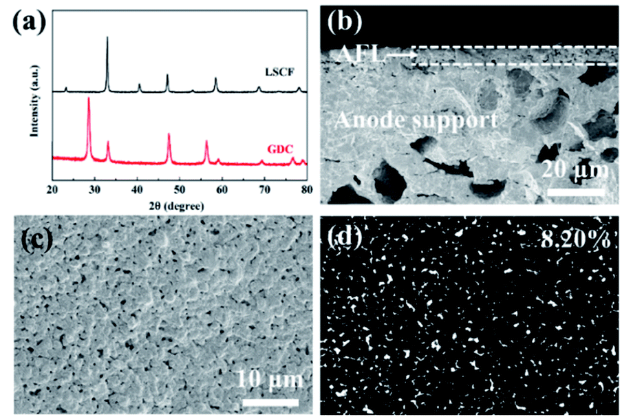 | ||
| Fig. 1 (a) XRD patterns of GDC and LSCF powders; (b) cross-sectional SEM image of the anode support and anode functional layers sintered at 1400 °C; (c and d) surface SEM image of the AFL. The pits on the AFL are detected and measured with ImageJ software. | ||
3.2. Single cells with YSZ electrolyte layer
| Ethanol/(ethanol + terpineol) | Viscosity (mPa s) | ||
|---|---|---|---|
| Ethanol–terpineol solvent | Ethanol–terpineol–EC solvent | Ethanol–terpineol–EC–YSZ slurry | |
| 0 wt% | 24.0 | — | — |
| 25 wt% | 7.0 | 18.0 | 24.0 |
| 35 wt% | 5.0 | 10.5 | 14.5 |
| 45 wt% | 3.5 | 7.0 | 11.5 |
| 55 wt% | 2.8 | 4.5 | 8.0 |
Fig. 2 shows the morphology of the electrolyte layers with various ethanol contents in the solvent. With 50 wt% YSZ in the electrolyte slurry, the thickness of the two-cycle YSZ layer after sintering is about 25 μm, which is almost unaffected by the content of ethanol. On the contrary, the ethanol content in the solvent of the electrolyte slurry shows a remarkable influence on the porosity of the electrolyte layer. The YSZ layer with 25 wt% ethanol in the solvent exhibits a high surface porosity of 5.16%, which is probably due to the relatively high viscosity (24.0 mPa s) of the electrolyte slurry, resulting in an uneven distribution of the YSZ powder.28 The YSZ slurry with 35 wt% ethanol in the solvent shows a moderate viscosity (14.5 mPa s), and thus the corresponding electrolyte layer has the lowest surface porosity of 1.24%. The further addition of ethanol in the solvent leads to an increase of the surface porosity to 3.5–4.3%. The YSZ slurry with a low viscosity (8–11.5 mPa s) may partly permeate into the AFL during the spin-coating and the drying processes (Fig. 2c and d), rising the porosity of the electrolyte layer.37
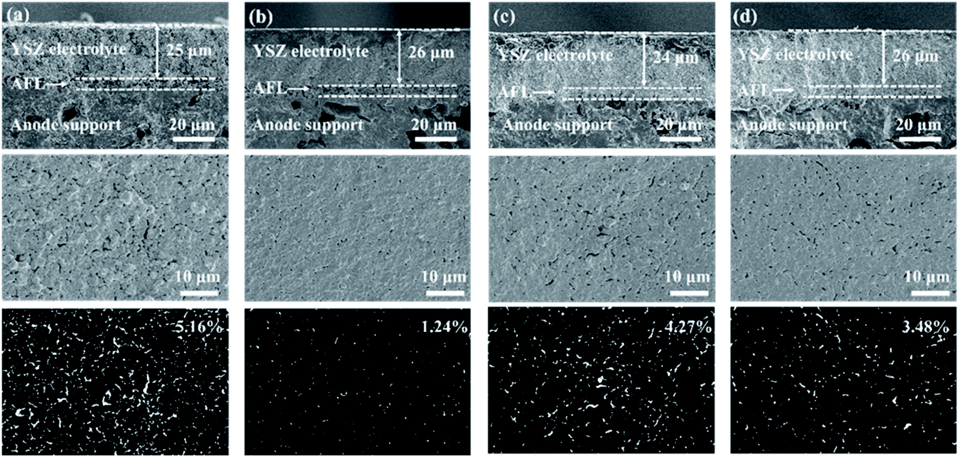 | ||
| Fig. 2 Cross-sectional and surface SEM images of the two-cycle YSZ layers with (a) 25 wt%, (b) 35 wt%, (c) 45 wt% and (d) 55 wt% ethanol in the solvent. The YSZ content in the electrolyte slurry is 50 wt%. The pits on the surface of the electrolyte layers are detected and measured with ImageJ software. | ||
The current–voltage (I–V) and current–power (I–P) characteristics of the single cells at 750 °C are presented in Fig. 3. The open circuit voltage (OCV) of the 25 wt%-ethanol cell is only 0.83 V due to the high porosity of the electrolyte layer, and the Pmax is 454 mW cm−2. The 35 wt%-ethanol cell with the most compact electrolyte film shows the highest OCV and Pmax of 1.07 V and 1136 mW cm−2, respectively. The OCV and Pmax of the cell both drop with more ethanol in the solvent of the electrolyte slurry due to the porosity increase of the YSZ membrane.
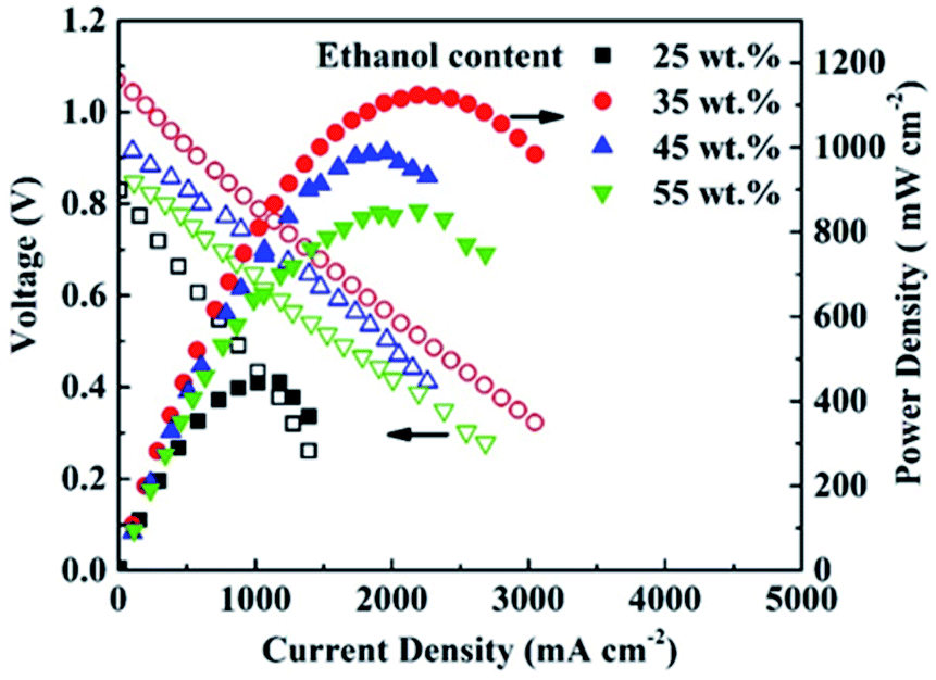 | ||
| Fig. 3 I–V and I–P curves of the single cells at 750 °C with various ethanol contents in the solvent. | ||
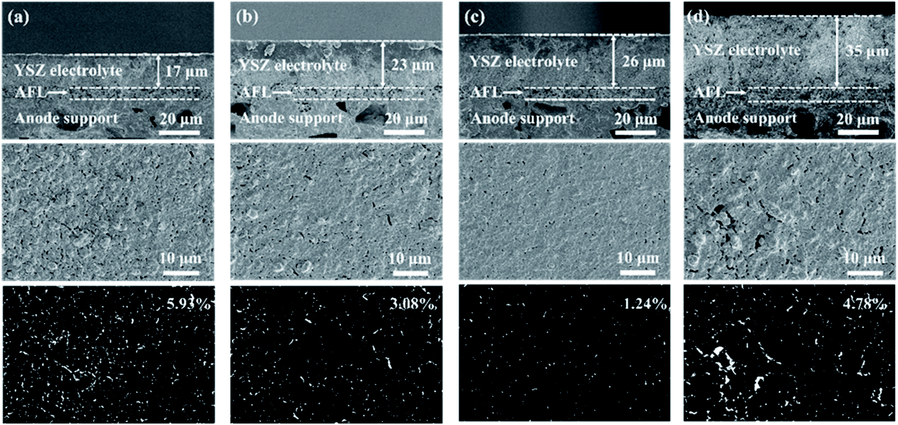 | ||
| Fig. 4 Cross-sectional and surface SEM images of the two-cycle YSZ layers with (a) 25 wt%, (b) 30 wt%, (c) 35 wt% and (d) 40 wt% YSZ in the electrolyte slurry. The ethanol content in the solvent is 35 wt%. The pits on the surface of the electrolyte layers are detected and measured with ImageJ software. | ||
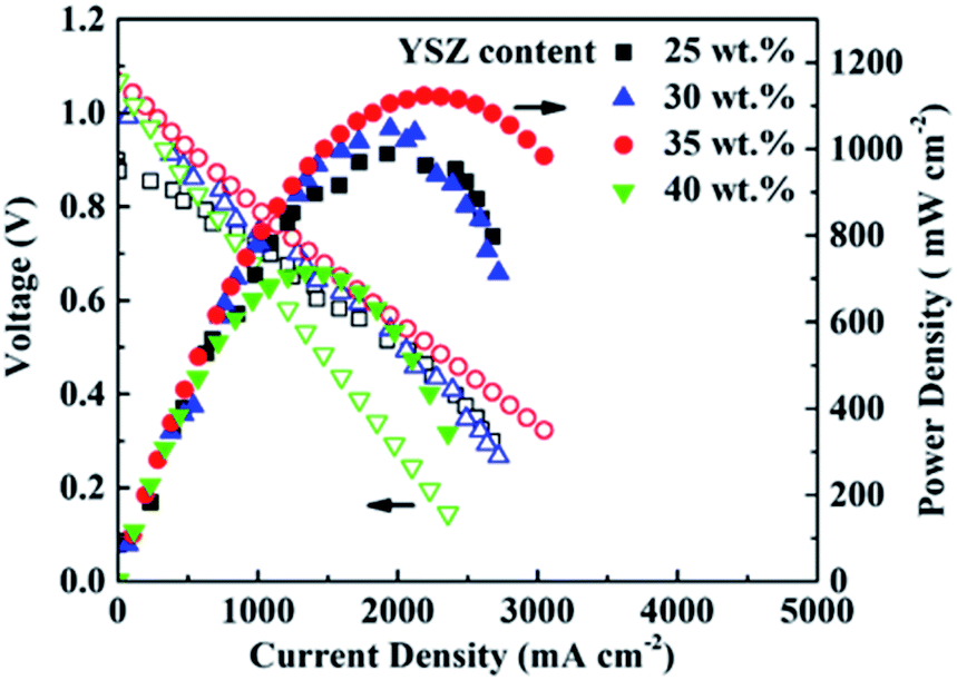
The I–V and I–P curves of the single cells at 750 °C are presented in Fig. 5. The OCV of the 25 wt%-YSZ cell with the highest porosity of the electrolyte layer is 0.91 V, and the corresponding Pmax is 998 mW cm−2. The OCVs of the cells with higher YSZ contents are in the range of 1.00–1.07 V. The Pmax of 30 wt%-YSZ and 35 wt%-YSZ cells are 1066 and 1136 mW cm−2, respectively. When the amount of YSZ in the slurry reaches 40 wt%, the Pmax of the cell decreases to 725 mW cm−2 mainly due to the high ohmic resistance of the thick electrolyte layer.
 | ||
| Fig. 5 I–V and I–P curves of the single cells at 750 °C with various YSZ contents in the electrolyte slurry. | ||
3.3. Single cells with YSZ/GDC bi-layer electrolyte
The surface SEM images of the one-cycle YSZ layers sintered at various temperatures are shown in Fig. 6. The average size of YSZ particles sintered at 420 °C is about 50 nm, which increases to about 100 and 200 nm when the temperature rises to 1000 and 1100 °C, respectively. The grain growth of YSZ is more obvious when the temperature is higher than 1200 °C.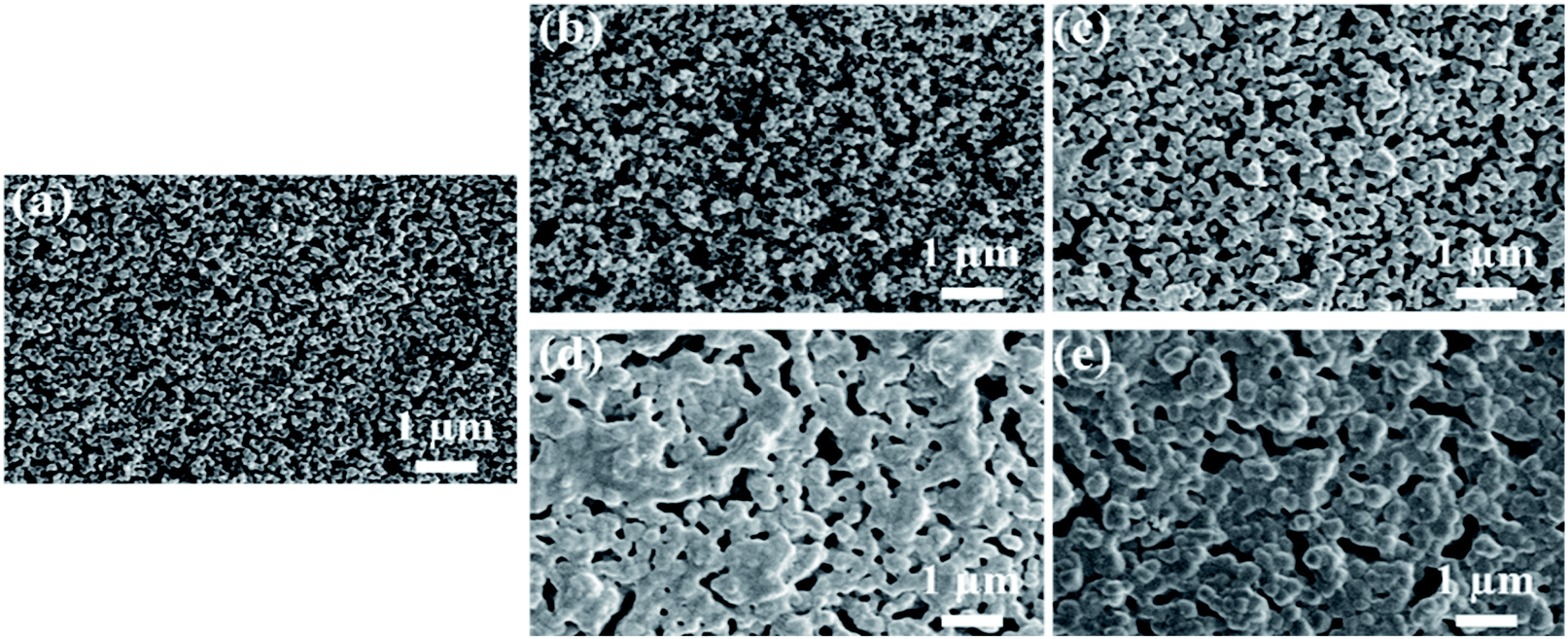 | ||
| Fig. 6 Surface SEM images of the one-cycle YSZ layers sintered at (a) 420 °C, (b) 1000 °C, (c) 1100 °C, (d) 1200 °C and (e) 1300 °C. | ||
The cross-sectional and surface SEM images of the one-cycle YSZ layer sintered at 1400 °C are shown in Fig. 7a. The YSZ layer shows a thickness of about 9 μm and a surface porosity of 1.83%. The infiltration of GDC into the YSZ layer is found in the YSZ/GDC bi-layer electrolytes in which the YSZ layer was pre-sintered at 1000 °C (Fig. 7b), 1100 °C (Fig. 7c) and 1200 °C (Fig. 7d), resulting in a YSZ/GDC composite layer on the surface. The YSZ layer pre-sintered at a lower temperature has a smaller grain size and a larger porosity (Fig. 6), leading to a deeper infiltration of GDC. Meanwhile, the surface roughness of the YSZ layer is reduced with the increase of the pre-sintering temperature, resulting in a weak interaction between the YSZ layer and the GDC slurry, and thus less GDC slurry remains on the YSZ layer after spin-coating. The thicknesses of the composite layers on YSZ-1000, YSZ-1100 and YSZ-1200 are 3.8, 2.5 and 1.4 μm, respectively. The YSZ/GDC composite layers are much denser than the YSZ layer, and the composite electrolyte layer on YSZ-1200 has the lowest surface porosity of 0.23%. Only a small amount of GDC is found on the surface of YSZ-1300 without the formation of a noticeable YSZ/GDC composite layer (Fig. 7e) probably due to the large grain size and the low porosity of YSZ-1300, which weakens the interaction between the YSZ layer and the GDC slurry during the spin-coating process. Nonetheless, the surface porosity of the YSZ layer is reduced to 0.57%, indicating the infiltration of a small amount of GDC into the YSZ-1300 layer.
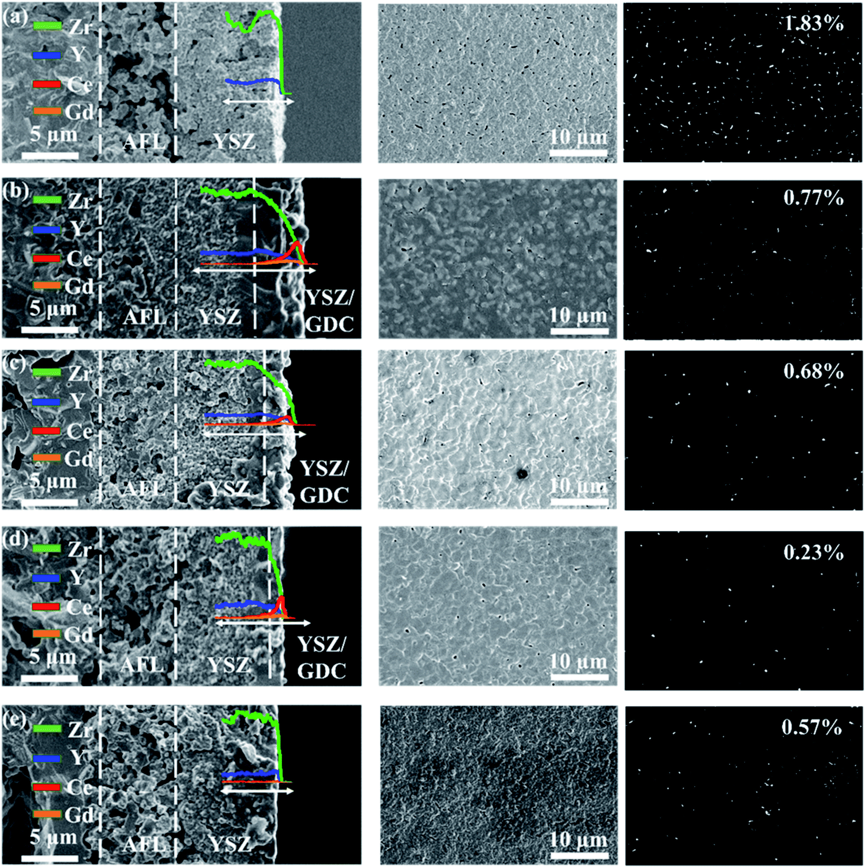 | ||
| Fig. 7 Cross-sectional SEM images with the line-scanning results and surface SEM images of (a) one-cycle YSZ layer, and YSZ/GDC bilayers in which the YSZ layer was pre-sintered at (b) 1000 °C, (c) 1100 °C, (d) 1200 °C and (e) 1300 °C. The pits on the surface of the electrolyte layers are detected and measured with ImageJ software. | ||
The EIS results of the single cells with YSZ/GDC electrolyte layers at 750 °C are presented in Fig. 8a. The high-frequency intercept of the curve on the real axis reflects the ohmic resistance (Ro) of the cell, and the arc corresponds to the polarization resistance (Rp). The YSZ-1000 cell shows the largest Ro due to its thickest electrolyte layer. Moreover, the insulating Ce–Zr solid solution probably formed between the YSZ and GDC phases leads to the increase of both Ro and Rp. As a result, the YSZ-1000 cell shows the lowest Pmax of 460 mW cm−2 at 750 °C (Fig. 8b). The interaction between the YSZ and GDC phases is weakened with the increase of the pre-sintering temperature of the YSZ membrane, resulting in the decrease of Ro and Rp. The YSZ-1200 cell has the lowest Ro and Rp and consequently the highest Pmax of 1480 mW cm−2 at 750 °C. However, Ro increases when the pre-sintering temperature of the YSZ layer rises to 1300 °C probably due to the absence of the GDC interlayer, leading to the interaction between the YSZ electrolyte and the LSCF cathode. The Pmax of the cell decreases with the drop of the operating temperature. The YSZ-1200 cell exhibits Pmax of 872, 472 and 215 mW cm−2 at 700, 650 and 600 °C, respectively (Fig. 8c). The short-term durability of the YSZ-1200 cell was tested at 700 °C with an output current density of 500 mA cm−2 (Fig. 8d). The output voltage decreases gradually from 0.79 V to 0.70 V during the first 7 h, and decreases slowly to 0.63 V in the next 33 h, indicating a promising stability of the single cell with a YSZ/GDC bi-layer electrolyte.
 | ||
| Fig. 8 (a) EIS results and (b) I–V and I–P curves of the single cells with YSZ/GDC bilayers at 750 °C in which the YSZ layers were pre-sintered at various temperatures; (c) I–V and I–P curves of the YSZ-1200 cell at various temperatures; (d) durability of the YSZ-1200 cell at 700 °C under a constant output current density of 500 mA cm−2. | ||
4. Conclusion
In this work, YSZ and YSZ/GDC electrolyte layers are fabricated with the slurry spin coating method. A lower ethanol content in the terpineol solvent and a higher YSZ content result in a higher viscosity of the YSZ slurry. The thickness of the YSZ film is influenced negligibly by the viscosity but increases with the YSZ content of the slurry. The most compact YSZ layer is produced using a slurry with 35 wt% ethanol in the solvent and 35 wt% YSZ in the slurry. The YSZ layer is pre-sintered at various temperatures, and the interaction between the YSZ membrane and the GDC slurry is weakened with the rise of the pre-sintering temperature. A strong interaction leads to the formation of insulating Ce–Zr solid solution, while a weak interaction results in insufficient adherence of GDC to the YSZ membrane. The YSZ-1200 cell shows the highest Pmax of 1480 mW cm−2 at 750 °C. The cell also exhibits a promising stability.Conflicts of interest
There are no conflicts to declare.Acknowledgements
The financial support from National Natural Science Foundation of China under contract number 22075205 and the support of Tianjin Municipal Science and Technology Commission under contract number 19JCYBJC21700 are gratefully acknowledged. The work has been also supported by the Program of Introducing Talents to the University Disciplines under file number B06006, and the Program for Changjiang Scholars and Innovative Research Teams in Universities under file number IRT 0641.References
- P. Boldrin, E. Ruiz-Trejo, J. Mermelstein, J. M. B. Menendez, T. R. Reina and N. P. Brandon, Chem. Rev., 2016, 116, 13633–13684 CrossRef CAS PubMed.
- P. A. Connor, X. L. Yue, C. D. Savaniu, R. Price, G. Triantafyllou, M. Cassidy, G. Kerherve, D. J. Payne, R. C. Maher, L. F. Cohen, R. I. Tomov, B. A. Glowacki, R. V. Kumar and J. T. S. Irvine, Adv. Energy Mater., 2018, 8, 1800120 CrossRef.
- N. Mahato, A. Banerjee, A. Gupta, S. Omar and K. Balani, Prog. Mater. Sci., 2015, 72, 141–337 CrossRef CAS.
- S. Buyukkilic, S. Kim and A. Navrotsky, Angew. Chem., Int. Ed., 2014, 53, 9517–9521 CrossRef CAS PubMed.
- D. Kalaev, T. Defferriere, C. Nicollet, T. Kadosh and H. L. Tuller, Adv. Funct. Mater., 2020, 30, 1907402 CrossRef CAS.
- T. Ishihara, H. Matsuda and Y. Takita, J. Am. Chem. Soc., 1994, 116, 3801–3803 CrossRef CAS.
- E. D. Wachsman and K. T. Lee, Science, 2011, 334, 935–939 CrossRef CAS PubMed.
- P. Singh and J. B. Goodenough, J. Am. Chem. Soc., 2013, 135, 10149–10154 CrossRef CAS PubMed.
- T. Wei, P. Singh, Y. H. Gong, J. B. Goodenough, Y. H. Huang and K. Huang, Energy Environ. Sci., 2014, 7, 1680–1684 RSC.
- M. Li, M. J. Pietrowski, R. A. De Souza, H. R. Zhang, I. M. Reaney, S. N. Cook, J. A. Kilner and D. C. Sinclair, Nat. Mater., 2014, 13, 31–35 CrossRef CAS PubMed.
- C. C. Duan, J. H. Tong, M. Shang, S. Nikodemski, M. Sanders, S. Ricote, A. Almansoori and R. O'Hayre, Science, 2015, 349, 1321–1326 CrossRef CAS PubMed.
- Y. Zhou, X. F. Guan, H. Zhou, K. Ramadoss, S. Adam, H. J. Liu, S. Lee, J. Shi, M. Tsuchiya, D. D. Fong and S. Ramanathan, Nature, 2016, 534, 231–234 CrossRef CAS PubMed.
- B. C. H. Steele and A. Heinzel, Nature, 2001, 414, 345–352 CrossRef CAS PubMed.
- J. H. Park, S. M. Han, B. K. Kim, J. H. Lee, K. J. Yoon, H. Kim, H. I. Ji and J. W. Son, Electrochim. Acta, 2019, 296, 1055–1063 CrossRef CAS.
- B. C. Yang, S. Kye, D. Go, S. Oh, H. J. Kim, J. W. Shin, G. Y. Cho and J. An, Ceram. Int., 2021, 47, 11372–11378 CrossRef CAS.
- D. Y. Jang, M. Kim, J. W. Kim, K. Bae, J. W. Son, M. V. F. Schlupp and J. H. Shim, J. Electrochem. Soc., 2017, 164, F484–F490 CrossRef CAS.
- S. Ryu, W. Yu, I. Chang, T. Park, G. Y. Cho and S. W. Cha, Ceram. Int., 2020, 46, 12648–12655 CrossRef CAS.
- C. Viazzi, V. Rouessac, P. Lenormand, A. Julbe, F. Ansart and C. Guizard, J. Power Sources, 2011, 196, 2987–2993 CrossRef CAS.
- A. Mineshige, A. Saito, M. Kobayashi, H. Hayakawa, M. Momai, T. Yazawa, H. Yoshioka, M. Sakao, R. Mori, Y. Takayama, Y. Kagoshima and J. Matsui, J. Power Sources, 2020, 475, 228543 CrossRef CAS.
- K. R. Lee, C. J. Tseng, S. C. Jang, J. C. Lin, K. W. Wang, J. K. Chang, T. C. Chen and S. W. Lee, Int. J. Hydrogen Energy, 2019, 44, 23784–23792 CrossRef CAS.
- J. M. Wang, Z. Lu, K. F. Chen, X. Q. Huang, N. Ai, J. Y. Hu, Y. H. Zhang and W. H. Su, J. Power Sources, 2007, 164, 17–23 CrossRef CAS.
- S. N. Chen, D. G. Gu, Y. F. Zheng, H. Chen and L. C. Guo, J. Mater. Sci., 2020, 55, 88–98 CrossRef CAS.
- E. H. Kang, H. R. Choi, J. S. Park, K. H. Kim, D. H. Kim, K. Bae, F. B. Prinz and J. H. Shim, J. Power Sources, 2020, 465, 228254 CrossRef CAS.
- S. Molin, A. Chrzan, J. Karczewski, D. Szymczewska and P. Jasinski, Electrochim. Acta, 2016, 204, 136–145 CrossRef CAS.
- H. J. Kim, M. Kim, K. C. Neoh, G. D. Han, K. Bae, J. M. Shin, G. T. Kim and J. H. Shim, J. Power Sources, 2016, 327, 401–407 CrossRef CAS.
- T. Van Gestel, D. Sebold, H. P. Buchkremer and D. Stover, J. Eur. Ceram. Soc., 2012, 32, 9–26 CrossRef CAS.
- S. Vieweger, R. Mucke, N. H. Menzler and H. P. Buchkremer, Fuel Cells, 2013, 13, 556–564 CrossRef CAS.
- P. Plonczak, M. Joost, J. Hjelm, M. Sogaard, M. Lundberg and P. V. Hendriksen, J. Power Sources, 2011, 196, 1156–1162 CrossRef CAS.
- S. Hwang, J. Lee, G. Kang, M. Choi, S. J. Kim, W. Lee and D. Byun, J. Mater. Chem. A, 2021, 9, 11683–11690 RSC.
- I. Jang, S. Kim, C. Kim, H. Lee, H. Yoon, T. Song and U. Paik, J. Power Sources, 2019, 435, 226776 CrossRef CAS.
- A. Tsoga, A. Naoumidis, W. Jungen and D. Stover, J. Eur. Ceram. Soc., 1999, 19, 907–912 CrossRef CAS.
- L. A. Chick, L. R. Pederson, G. D. Maupin, J. L. Bates, L. E. Thomas and G. J. Exarhos, Mater. Lett., 1990, 10, 6–12 CrossRef CAS.
- P. Datta, P. Majewski and F. Aldinger, Mater. Charact., 2009, 60, 138–143 CrossRef CAS.
- C. S. Ding, H. F. Lin, K. Sato and T. Hashida, Scr. Mater., 2009, 60, 254–256 CrossRef CAS.
- Z. Liu, M. F. Han and W. T. Miao, J. Power Sources, 2007, 173, 837–841 CrossRef CAS.
- A. Ahuja, M. Gautam, A. Sinha, J. Sharma, P. K. Patro and A. Venkatasubramanian, Bull. Mater. Sci., 2020, 43, 129 CrossRef CAS.
- K. Lee, J. Kang, S. Jin, S. Lee and J. Bae, Int. J. Hydrogen Energy, 2017, 42, 6220–6230 CrossRef CAS.
- N. T. Yang, X. Y. Tan, X. X. Meng, Y. M. Yin and Z. F. Ma, ECS Trans., 2009, 25, 881–888 CrossRef CAS.
- H. L. Xie and P. C. Su, Thin Solid Films, 2015, 584, 116–119 CrossRef CAS.
| This journal is © The Royal Society of Chemistry 2022 |