 Open Access Article
Evolution of morphology and cohesive force of hydrate particles in the presence/absence of wax†
Yang Liu *a,
Chengxuan Wua,
Xiaofang Lv
 *ab,
Xinyi Xua,
Qianli Maa,
Jiawei Menga,
Shidong Zhou
 a,
Bohui Shi
 c,
Shangfei Songc and
Jing Gongc
aJiangsu Key Laboratory of Oil and Gas Storage and Transportation Technology, Changzhou University, Changzhou, Jiangsu 213164, China. E-mail: liu.y@cczu.edu.cn; chrisblack@foxmail.com; lvxiaofang5@cczu.edu.cn
bInstitute of Petroleum Engineering Technology, Sinopec Northwest Oil Field Company, Urumqi, Xinjiang 830011, China
cNational Engineering Laboratory for Pipeline Safety/State Key Laboratory of Natural Gas Hydrate, China University of Petroleum-Beijing, Beijing 102249, China
First published on 12th May 2022
Abstract
In the exploitation of deep-sea oil and gas resources, the multiphase production and transportation process is frequently plagued by pipeline blockage issues. Especially when hydrates and wax coexist simultaneously, the viscosity and plugging tendency of multiphase flow systems will synergistically increase. Understanding the evolution of morphology of hydrate particles and the agglomeration characteristics of hydrate particles in the presence or absence of wax crystals is crucial to flow assurance industry. With the assistance of a visualized reactor equipped with a three axis moving platform, microscopic images of cyclopentane hydrate during hydrate growth were obtained, and the cohesive force between hydrate particles was measured. It was found that during the hydrate growth on wax-free water droplets, the untransformed water inside the particles gradually wetted the surface of the particle. With the increase in temperature and contact time, the shell of hydrate particles changed from solid and rough to smooth and moist. The cohesive force measured in this work ranges from 3.14 ± 0.52 to 11.77 ± 0.68 mN m−1 with different contact times and temperature. When the contact time was 0 s and 10 s, the cohesive force between particles increased first and then stabilized with temperature. When the contact time was 20 s, the cohesive force was greater than the first two cases and showed an overall stable trend. An interesting phenomenon was also discerned: a large water bridge between particles formed during their separation process. For the wax-containing system, it required a longer time for water droplets to be converted into hydrate particles than that for wax-free systems. After wax participated in hydrate growth, hydrate particles showed the properties of elasticity and stickiness, which resulted in a larger liquid bridge between hydrate particles after their contact. It was suggested that wax crystal would alter the shell structure of hydrate particles, and change the surface properties of hydrate particles and the formation process of the liquid bridge, leading to significant and rapid increase in the cohesive force.
1 Introduction
Nowadays, the development, transportation and shortage of energy is a very noteworthy issue around the world. The shortage of energy resources makes people focus on obtaining energy from a riskier and severer environment. On one hand, hydrates in marine areas have attracted more and more attention. Natural gas hydrates are regarded as the succeeding potential energy guarantee that can replace traditional energy such as coal and oil.1 On the other hand, during the exploitation and transportation of deep-sea multiphase products, gathering pipelines often face high-pressure and low temperature transportation environment, which is prone to produce solid-phase deposition problems such as scaling, wax, asphaltene and hydrate.2 These matters may deposit on the pipe wall, thereby reducing the available area of flow in the pipeline.3 If they are not handled properly, these sediments will reduce pipeline efficiency, causing pipeline blockage, damage to stationary treatment facilities, and even cause casualties.4,5Moreover, the abovementioned solid deposits can also interact with each other, resulting in a higher pipeline blockage tendency.6–9 In order to avoid blockage of the gathering pipeline, it is necessary to predict the pressure drop and fluid viscosity of multiphase flow systems. Generally, hydrates formed in the gathering and transportation pipeline will agglomerate and form deposits, resulting in increased pressure drop and viscous fluid phase. When wax and hydrate coexist, it will greatly increase the difficulty of predicting the pressure drop of the gathering and transportation pipeline and the viscosity of the fluid, which is more likely to be increased the risk of pipeline blockage. At present, numerous studies have been carried out on the effect of wax on hydrate, including nucleation,11–16 formation,17–21 agglomeration,10,22–24 deposition,7 and blockage.22
In order to manipulate the blockage issues of gathering pipelines, it is necessary to predict the pressure drop and fluid viscosity of flow systems. Generally speaking, hydrate agglomeration would result in the increase in pressure drop and fluid viscosity. When wax and hydrate coexist, it will greatly increase the difficulty of predicting the pressure drop and fluid viscosity of the gathering pipeline, and thus increase the risk of pipeline blockage. Some studies have been conducted on the risk and the potential safety hazard of pipeline blockage in the coexistence system of wax and hydrate. Liu et al.22 studied the effect of wax on the formation, agglomeration, flow characteristics and plugging mechanism of hydrates in w/o emulsion systems. They suggested that the presence of wax would affect the agglomeration process of hydrate and greatly increase the risk of pipeline blockage. Liu et al.25 also studied the coupling rheological properties of wax and hydrate coexistence system, who found that the interaction among wax, hydrate particles and water droplets would increase the viscosity of slurry. They then established a viscosity model of wax hydrate slurry considering the phase interactions. Chen et al.9 carried out the hydrate formation experiments of waxy w/o systems in a high pressure reactor, and found that wax crystals had an inhibitory effect on hydrate nucleation. With the increase of wax content, the induction period of hydrate formation is prolonged. What is the relationship between the macroscopic parameters, such as hydrate induction time and slurry viscosity, and microscopic particle behaviors, such as particle agglomeration? Researchers in the field of flow assurance have put efforts in clarifying the aggregation mechanism of the micro-force between hydrate particles in oil–water systems and investigating the various factors that cause hydrate particle aggregation. This is also an important research topic that has to be solved urgently.
At present, it has been found that the factors affecting the cohesion between hydrate particles include temperature, time, undercooling, surfactant, additives (AAs, KHIs), salinity, capillary bridge, particle surface roughness, surrounding medium, etc. Taylor et al.26 used an improved micro-mechanical force measurement (MMF) device to study the interaction between hydrate particles and found that the contact between particles will form a liquid bridge-like connection. These capillary liquid bridge theories can be used to explain the change of force and the change trend of force measured experimentally. Song et al.27,28 studied the effect of KHI and wax on the growth of hydrate particles, and concluded that KHI reduced the growth rate of hydrate and changed the wettability of hydrate. They also found that the presence of wax altered the morphology of hydrate particles.
Currently, although there are limited studies reporting the growth of hydrate particles and the cohesion between particles via microscopic apparatus, the evolution of the morphology and cohesion of hydrate particles in the presence/absence of wax crystals has not been studied yet, resulting in the incomplete expression of the coalescence characteristics of the coexistence system. Therefore, in this paper, a self-made apparatus with the similar function as MMF was used to study the morphology change and cohesive force of both wax-containing and wax-free hydrate particles by controlling the two variables of time and temperature. The finds of this work can provide meaningful data and reference for the development of on-going deep-sea oil and gas reservoirs.
2 Experimental section
2.1 Experimental apparatus
In this experimental study, the morphology of hydrate growth in the presence of wax and the analysis of cohesive force between hydrate particles were carried out. The apparatus used throughout this study is mainly a high-pressure visualization micro-force test device, including: (1) A high pressure kettle (with water bath jacket and insulation layer), which is made of stainless-steel and equipped with a visual window of 55 mm2 area. The viewing window equipped above the kettle is made of sapphire with high light transparency. (2) A three axis moving platform, the XYZ direction moving distance of which is 10 mm. (3) Pressure control system and sensors with working pressure of 0–16 MPa and precision of 0.25%. (4) Temperature control system with working temperature ranging from −20 °C to 80 °C and accuracy of 0.1 °C. (5) Data acquisition system, which records temperature, pressure and microscopic videos in real-time. (6) A single lens digital microscope (VD-100V, Wuxi Mhago, China) is used in this work, which provides a wide zoom range of objective lens (0.7–4.5 times) and maximum magnification of 640 times. The digital microscope is connected to a computer via USB and includes a measuring software, so the real images and sizes of objects can be directly observed and measured on the computer screen. The magnification used in this work is 100 times. The photographs of hydrate particles are vertically taken by the camera from the top. (7) Pipes and valves.2.2 Experimental materials
Cyclopentane (CP, purity 96%, Aladdin), deionized water and solid paraffin were selected as the experimental materials. At atmospheric pressure, the hydrate formation equilibrium temperature of cyclopentane is 7.7 °C.30 Therefore, cyclopentane is used as the formation agent of the oil phase and hydrate. Furthermore, cyclopentane is incompatible with water and can form type II hydrate, which is also the structure of natural gas hydrate commonly formed in deep-sea natural gas pipelines.2.3 Experimental method
In the experiment, the morphological changes during hydrate growth as well as the contact and separation between hydrate particles of wax-free and wax-containing systems were recorded. The displacement between particles was also measured, so as to calculate the cohesive force. The main operation process of the experiment included the preparation of wax-containing cyclopentane solution, the formation of hydrate particles and the measurement of cohesive force. For wax-containing systems, solid paraffin particles were first weighted by an electronic balance and then dissolved into the pure cyclopentane.Two glass fiber rods were set in the same horizontal plane with certain distance in the reactor tank. Water droplets and/or cyclopentane droplets were produced on the glass fiber rods by micro syringes with a maximum volume of 500 μL. In the experimental operation, the temperature in the reaction tank was controlled in a range of −1 °C to 0.5 °C, and the experiments are always conducted under ambient atmospheric pressure. First, water droplets were dropped on the glass fiber rod through the liquid shifter, and then the prepared waxy cyclopentane solution was continued to drop on the water droplets to induce the nucleation of cyclopentane hydrate. Similarly, hydrate formation in the absence of wax was carried out. During the experiment, microscope and camera were used to record hydrate contact phenomenon and conduct cohesion measurement. All discussions are based on microscopic observations.
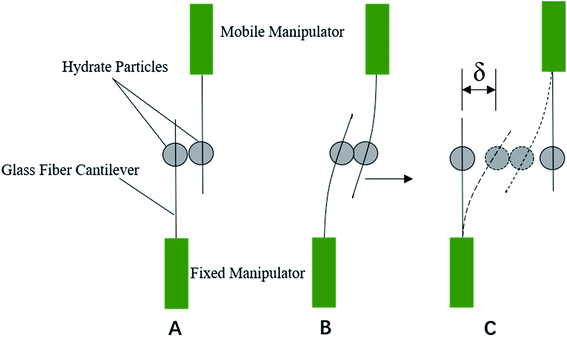
The cohesive force between hydrate particles was measured by the principle of Hooke's law, as shown in Fig. 1. After connecting the microscope and the microscopic operating device, the contact and separation between particles are operated by manipulating the microscopic operating arm. The operating arm consists of a fixed arm and a moving arm. Due to the existence of cohesive force between particles, when the operating arm was motivated by the manual runners (XYZ axis), a glass fiber rod was fixed, while another glass fiber rod moved. Then the glass fiber rod on the mobile operating arm would bend (see Fig. 1B and C), and the hydrate particles on the glass fiber would move accordingly. Then the operating arm was continuously moved, the elastic force of the glass fiber would be greater than the cohesive force between the hydrate particles when the critical value δ was reached. The interaction between the hydrate particles was destroyed, and two hydrate particles were separated. According to Hooke's law, the cohesive force between particles F and the separation distance of hydrate particles δ has the following relationship with the elastic coefficient k of glass:
| F = kδ | (1) |
Table 1 tabulates the experimental sets with different conditions. Contact temperature refers to the temperature when two hydrate particles are contacted. Contact time refers to the duration after the contact of two particles: 0 s means that two particles were pulled away immediately after the contact. In this study, hydrate particles in each group were subjected to 40 times of contact and pull-off operation, which makes the measurement results accurate and reliable to the greatest extent. The acquired experimental image was analyzed by the measuring software (during experiments) that is connected to the microscope as well as Image J® (after experiments) to directly determine the moving distance of particles, and the width of liquid bridge between particles was measured. Obtained cohesion results are expressed in the form of calculating the average value, the standard deviation or calculating the variance of the results obtained from 40 operations.
| Experimental no. | Contact temperature (°C) | Contact time (s) | Wax content (wt%) |
|---|---|---|---|
| Case 1 | 0.1 | 0/10/20 | 0 |
| Case 2 | 0.15 | 0/10/20 | 0 |
| Case 3 | 0.2 | 0/10/20 | 0 |
| Case 4 | 0.25 | 0/10/20 | 0 |
| Case 5 | 0.3 | 0/10/20 | 0 |
| Case 6 | 0.35 | 0/10/20 | 0 |
| Case 7 | 0.4 | 0/10/20 | 0 |
| Case 8 | 0.45 | 0/10/20 | 0 |
| Case 9 | 0.5 | 0/10/20 | 0 |
| Case10 | 0.1 | 0/10/20 | 0.1 |
3 Results and discussion
3.1 Morphology evolution of hydrate growth without wax
In this study, we first studied the static growth of hydrate on the droplet surface in the wax-free system. Fig. 2 shows the typical experimental phenomena observed in the wax-free system at contact temperature of 0.3 °C. Based on these experimental observations (Fig. 2a–g), we can summarize some characteristics of hydrate growth in the wax-free system: hydrate particles have a complete hydrate shell, and the surface of the hydrate shell possesses certain roughness. A large number of capillaries are distributed on these rough surfaces, so that liquid bridge can be formed between hydrate particles, which is the main reason for the aggregation of hydrate particles.5 Over time, the shell surface of hydrate particles gradually becomes smooth, which may be caused by the gradual surface wetting of hydrate particles due to the untransformed water inside the hydrate particle. | ||
| Fig. 2 Change of hydrate particles morphology from 0 s to 30 min during hydrate growth process at 0.3 °C. | ||
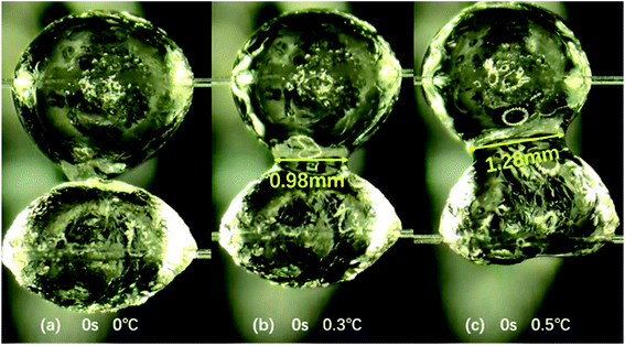
Secondly, the variation of particle morphology with contact temperature during the coalescence of hydrate particles was studied. When the two hydrate particles contact, the change of temperature at the same contact time will also affect the morphology of hydrate particles. Fig. 3 describes this change. As shown in Fig. 3a, when two hydrate particles contact at 0.1 °C, there is no obvious change in the particle surface, and the shell of hydrate particles is still in a rough and hard state. However, as shown in Fig. 3b and c, with the increase of temperature (0.3 °C and 0.5 °C), the shell on the surface of hydrate particles becomes smooth and is gradually wetted by water inside the particles. At relatively high temperature, when two hydrate particles contact (contact time of 0 s), the shell of hydrate particles is damaged and the liquid bridge appears. With the increase of temperature, the width of water bridge, i.e., the contact area, between the two hydrate particles also increases (see the yellow mark in Fig. 3). This leads to the enhancement of the liquid bridge effect, and the cohesive force between particles increases with the increase in temperature (see Subsection 3.3).
In addition, it is observed through the microscope that the contact time of hydrate particles also affects the state of hydrate particles under the same temperature. Through the comparative analysis of hydrate particles under three conditions in Fig. 4, it is found that at the same temperature, with the increase in contact time of two hydrate particles, the surface of the particles becomes smoother, the surface roughness decreases, and the liquid bridge between two particles is easier to form. In Fig. 4, it can be discerned that at 0.1 °C, the particle state does not change significantly at 0 s and 10 s. But the obvious liquid bridge appears at 20 s, and the width of the liquid bridge is 0.85 mm. However, even with a longer contact time than 20 s, the width of the liquid bridge did not change significantly. In this study, the hydrate particle states with contact time of 0 s, 10 s and 20 s are observed and discussed. In Fig. 5, for the states with 0 s and 10 s, the particle appearance changes significantly with the increase in temperature. But for that with 20 s, the particle appearance with temperature basically maintains unchanged. In the following discussion, the actual experimental measurement data will also be used to illustrate the effect of temperature on the cohesion of hydrate particles.
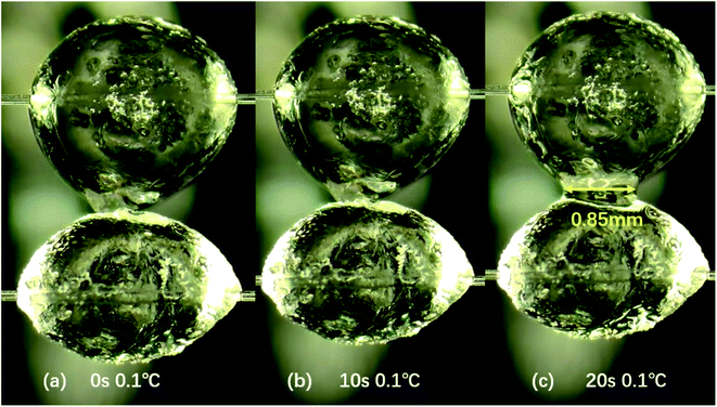 | ||
| Fig. 4 The effect of contact time on hydrate particle morphology at the same temperature. The liquid bridge width between hydrate particles is 0.85 mm at 0.1 °C. | ||
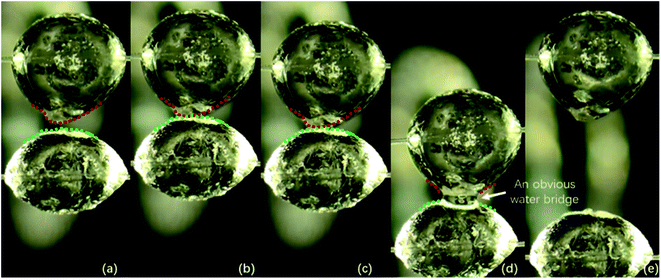
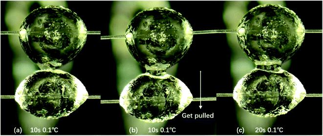
Notably, for the case with the contact time of 10 s and the temperature of 0.1 °C, there is no liquid bridge between the two hydrate particles during the contact time (see Fig. 6b). However, during the separation operation, when the hydrate particles on the glass fiber rod are pulled, there is a liquid bridge between the two hydrate particles. In Fig. 6, the four processes (a), (b), (c) and (d) respectively represent the two hydrate particles before contact, during contact, during pull-out with obvious liquid bridge and after pull-out, i.e., the measurement process of cohesive force. As obviously seen in Fig. 6b and c, the outlines of these two particles remains unchanged after the contact, indicating that no obvious water bridge emerges. Fig. 6d clearly depicts that the outlines of these two particles changes, thus indicating the emergence of an obvious water bridge. It is suggested that after two hydrate particles are merged due to contact,27 the shell of the hydrate surface is stretched under the action of tension when they are pulled out. The untransformed water inside the hydrate particles overflows, and then quickly transformed into hydrate. In other words, a liquid bridge is also formed during particle separation and the cohesive force between particles increases significantly (see Subsection 3.3). The mechanism of this phenomenon deserves further study, and attention should be paid by flow assurance industries to the development of high condensate gas reservoirs where this scenario may occur.
3.2 Evolution of hydrate growth morphology in the presence of wax
In this study, observation experiments of hydrate particle morphology during hydrate growth of 0.1 wt% wax-containing system were also carried out. Fig. 7 illustrates the growth process of hydrate particles in the presence of wax. As shown in Fig. 7a, hydrate particles begin to form. It is found that the surface of the particles is smooth, and hydrate crystals grow inside the particle, resulting in the transparent appearance of the particle. Fig. 7b and c shows the continual growth of hydrate particle, the surface of which is rough and uneven. The shell layer on the particle surface possesses certain interfacial strength. Fig. 7d depicts that some white fuzzy matter precipitates on the surface of hydrate particle. The particle is then partially wrapped, which is not as bright and transparent as its initial state. It can be found from Fig. 7e and f that the surface of hydrate particle is completely wrapped, and the surface of hydrate particles is dull and rough. These phenomena are presumably attributed to the participation of wax crystals in hydrate growth, leading to different morphologies of hydrate particle compared with the wax-free systems. | ||
| Fig. 7 Morphology evolution of growth process of hydrate particle for 0.1 wt% wax-containing system. | ||
Moreover, taking case 1 and case 10 in to comparison, it can be seen that under the same experimental conditions, the hydrate growth rate in the presence of wax is noticeably slower than that in the absence of wax. As shown in Fig. 7, the required time for water droplets to complete hydrate growth for wax-containing system is approximately 8 min, while that for wax-free system is much shorter (<2 min). It is suggested that the wax crystal that precipitates at the gas–liquid interface limits the mass and heat transfer process of hydrate growth, leading to the decrease in hydrate growth rate. In addition, the wax crystal at the interface obviously changed the appearance of hydrate particles.
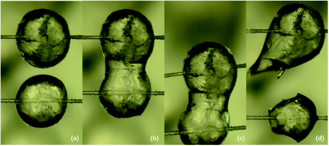
Subsequently, the cohesion measurement experiment was carried out. It is found that the hydrate particles in the presence of wax possess strong elasticity, which can restore the original state after the imposed load through a rigid bar is moved, as shown in Fig. 8a. The wax crystals at the gas–liquid interface interfere with the rigid state of the hydrate particles, which make the hydrate particles sticky. After the contact of waxy hydrate particles, the shell that wraps the particles is easily broken. Then the untransformed water inside quickly pours out, thus forming a large liquid bridge (see Fig. 8b), which greatly increases the cohesive force between waxy hydrate particles. Fig. 9 illustrates the contact-pulling out operation of waxy hydrate particles. Fig. 9a is the image before the contact of two hydrate particles, and Fig. 9b shows once two hydrate particles contact, a huge liquid bridge emerges. Fig. 9c shows that even under higher tension, the hydrate particles still cannot be divided. It can be seen that the liquid bridge is elongated and the cohesive force increases significantly. Fig. 9d depicts that under the action of external force, the shape of two particles can no longer restore to the original state: two particles with similar size before contact finally become a larger one and a smaller one with irregular morphology. In other words, the particle appearance is completely destroyed after the forced separation of the two particles, which suggests a high cohesive force between waxy hydrate particles.
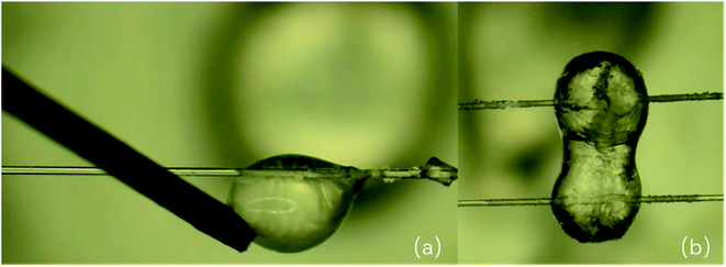 | ||
| Fig. 8 (a) The waxy hydrate particle possesses elasticity. (b) The shell of waxy hydrate particles is destroyed after contact, and a huge liquid bridge appears between particles. | ||
3.3 Evolution of interparticle cohesion
In this study, the cohesive force between hydrate particles was repeatedly tested, and the cohesive force was calculated and quantitatively analyzed according to Hooke's law. Fig. 10 shows the relationship between the particle cohesive force and temperature at different contact time. The experimental data in Fig. 10 are consistent with the experimental results of other researchers30,32–34 in order of magnitude (details can be found in ESI†). Therefore, the homemade device used in this study could ensure the accuracy and repeatability of the measurement. Combining with the analysis of microscopic images, it is found that when the contact time is 0 s and 10 s, the cohesive force first increases and then stabilizes with the gradual increase in temperature. As shown in Fig. 10, when the contact time is 0 s and temperature is 0.1 °C, the cohesive force between particles is the smallest (3.14 mN m−1). Because the lower temperature, the stronger driving force of hydrate formation, and the higher conversion rate of water. Thus, the surface of particles cannot be fully wetted, and there is no obvious liquid bridge after the contact and pull of hydrate. On the other hand, with the increase in temperature, the driving force of hydrate formation decreases, and the surface of particles can be wetted by water gradually. Moreover, the liquid bridge formed by tensile failure on the surface of the hydrate shell is strong (e.g., case 1 with contact time of 10 s). Therefore, after the contact of hydrate particles, the cohesive force between particles increases. From a longitudinal point of view, cohesive force is sensitive to the contact time at low temperatures. But when the temperature increases, cohesive force is not sensitive to contact time. Especially for 0 s and 10 s, the cohesion is relatively close when the temperature is higher than 0.3 °C. However, when the contact time is 20 s, the cohesive force basically remains stable under different temperatures and it reaches the maximum when the temperature rises to 0.4 °C. This phenomenon can presumably be attributed to the following reason: it requires enough time for the establishment of water bridges, while 20 s may be adequate in this work. But due to the relatively low experimental temperature, the water bridge between particles is likely to convert to hydrate. When the temperature reaches 0.4 °C, the amount of liquid water on the surface of hydrate particles due to capillary attraction31 and the amount of converted water bridge is at the critical point, leading to the highest cohesive force among these cases. After that, with the increase in temperature, the driving force for the conversion of water bridge decreases slightly, and thus the cohesive force between particles decreases slightly. It should be noted that the experimental temperature range is narrow in this work, and thus the standard deviations of each case is much smaller. Thus, more experiments with a wider temperature range should be conducted in the future to verify the above conjecture.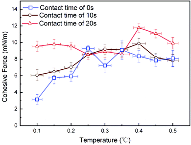 | ||
| Fig. 10 The variation of cohesion between hydrate particles with temperature at different contact time. | ||
It can also be concluded from the Fig. 10 that the contact time will also affect the cohesive force between particles. When the experimental temperature was 0.1 °C, the cohesive force between particles increases after the contact time increases (from 0 s to 20 s). According to Fig. 11, we can find that when the contact time is 10 s and the temperature is 0.1 °C, the liquid bridge does not appear when the particles contact (Fig. 11a), but the liquid bridge emerges during the pull-off operation (Fig. 11b). Under the same condition, when the contact time is 20 s, a liquid bridge between hydrate particles forms after the contact operation and before the pull-off operation (Fig. 11c). Therefore, it is concluded that there may be a critical point affecting cohesive force owing to the length of contact time between 10 s and 20 s. Because the conversion of liquid bridge into hydrate requires certain time. When the contact time is 20 s, the measured values of cohesive force remain stable, and are greater than that when the contact time is 10 s. According to the capillary bridge theory proposed by Aman,30 a wider water bridge leads to higher cohesive force between hydrate particles. Our experimental results are essentially consistent with the capillary bridge theory, while the effect of conversion of water bridge to hydrates should be considered in the future.
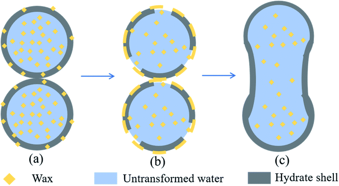
When the wax crystals exist, the cohesive force between hydrate particles increases significantly (>20 mN m−1). It can be found from Fig. 9b that the hydrate particles quickly form a bulky liquid bridge after contact. Fig. 9d indicates the appearance of the particles after pulling. It can be obviously seen that the morphology of the hydrate particles after pulling has been completely change, which is presumably caused by the elasticity and sticky of waxy hydrate particles. Therefore, it is very difficult for the hydrate particles to carry out separate-pulling measurement for wax-containing systems. The agglomeration between the waxy hydrates will result in the emergence of larger hydrate clusters. This experimental phenomenon is similar to that of Liu et al. who have conducted experiments in a flow loop.22 The reason is that wax crystal will destroy the shell structure of hydrate particles, changing the surface properties and liquid bridge formation process of hydrate particles, and making the cohesive force between hydrate particles increases steeply and sharply. Fig. 12 illustrates the aggregation mechanism of waxy hydrate particles. After the contact of hydrate particles that formed in the presence of wax crystals, it is suggested that the structure of wax-containing hydrate shell is destroyed due to the compatibility of wax crystals at the interface.22 The untransformed water inside the particles is rapidly flushed out, and a huge liquid bridge is rapidly formed between the two particles (see Fig. 8b), which greatly increases the cohesion between the wax-containing hydrate particles. It is difficult to separate them even with the largest tension of our apparatus. The agglomeration between the wax-containing hydrates will lead to the emergence of large hydrate clusters. This finding can provide reference for the study of rheological characteristics and plugging mechanism of wax and hydrate coexistence in deep-sea oil and gas exploitation.
4 Conclusions
In this paper, the measurement, quantitative and qualitative analysis of the growth of hydrate particles and the cohesion between particles without and with wax were studied, and the influence of temperature and contact time on the cohesion was analyzed.The growth of hydrates is summarized as follows: in the system without wax. The growth state of hydrates is stable and forms a stable and slightly rough hydrate shell. However, with the extension of time, the surface roughness of hydrate particles decreases and the surface becomes smooth, which may be due to the slow passage of converted water in hydrates through the hydrate shell. In the wax-containing system, the growth of hydrate in the early stage is similar to that without wax, but the wax precipitation will occur subsequently, resulting in the situation that the shell of hydrate is wrapped by the precipitated wax. Surface of hydrate is dim and dull, the shell strength of hydrate particles is reduced, and the interface will be elastic.
The cohesive force between hydrate particles is summarized as follows: in the system without wax, when the contact time is 0 s and 10 s, the cohesive force between hydrate particles increases first and then keeps stable with the increase of temperature. When the contact time is 20 s, the cohesion keeps a steady trend. When the temperature remains the same, the cohesion increases with the increase in contact time, and it is speculated that there is a critical point of contact time in the contact time of 10–20 s. In the wax-containing system, the cohesive force between hydrate particles increases markedly, and a large liquid bridge occurs after particle contact, and the cohesive force increases significantly. The hydrate will cause serious changes in the morphology of hydrate particles after external tension, which may cause greater hydrate agglomeration.
In the future work, it is necessary to carry out a more detailed experimental study on the cohesion between particles, and the influence of contact time, temperature and wax content on the cohesion is more detailed, so as to support the theory of deep-water flow assurance.
CRediT authorship contribution statement
Yang Liu: supervision, investigation, writing-original draft. Chengxuan Wu: investigation, writing-original draft. Xiaofang Lv: formal analysis, data curation. Xinyi Xu: data curation. Qianli Ma: formal analysis, writing-review. Jiawei Meng: data curation. Shidong Zhou: supervision, writing-review. Bohui Shi: validation, formal analysis. Shangfei Song: writing-review. Jing Gong: validation.Conflicts of interest
The authors declare no competing financial interest.Acknowledgements
This work was supported by the National Natural Science Foundation of China (Grant No. 52004039 & 51804046 & 51974037), Open Project of Jiangsu Key Laboratory of Oil-gas Storage and Transportation Technology (Grant No. CDYQCY202102), China Postdoctoral Science Foundation (Grant No. 2021M693908) and major project of universities affiliated to Jiangsu Province Basic Science (Natural Science) Research (No. 21KJA440001), all of which are gratefully acknowledged.References
- J. Gong, W. Wang, et al. Flow Safety Guarantee of Offshore Oil and Gas Mixed Pipeline. Science Press, Beijing, 2015 Search PubMed.
- Z. R. Chong, S. H. B. Yang, P. Babu, P. Linga and X.-S. Li, Review of Natural Gas Hydrates as an Energy Resource: Prospects and Challenges, Appl. Energy, 2016, 162, 1633–1652 CrossRef.
- E. P. Brown and C. A. Koh, Phys. Micromechanical measurements of the effect of surfactants on cyclopentane hydrate shell properties, Phys. Chem. Chem. Phys., 2016, 18, 594–600 RSC.
- E. D. Sloan, C. A. KOH, A. K. Sum, et al. Natural gas hydrates in flow assurance. Gulf Professional Publishing, Oxford, 2010 Search PubMed.
- E. D. Sloan and C. A. KOH. Clathrate hydrates of natural gases. CRC Press, New York, 2007 Search PubMed.
- E. P. Brown, D. Turner, G. Grasso and C. A. Koh, Effect of wax/anti-agglomerant interactions on hydrate depositing systems, Fuel, 2020, 264, 116573 CrossRef CAS.
- S. Q. Gao, Investigation of interactions between gas hydrates and several other flow assurance elements, Energy Fuels, 2008, 22(5), 3150–3153 CrossRef CAS.
- M. C. K. D. Oliveira, A. Teixeira and L. C. Vieira, et al. Flow assurance study for waxy crude oils, Energy Fuels, 2012, 26(5), 2688–2695 CrossRef.
- Y. C. Chen, B. H. Shi and Y. Liu, et al. Experimental and Theoretical Investigation of the Interaction between Hydrate Formation and Wax Precipitation in Water-in-Oil Emulsions, Energy Fuels, 2018, 32(9), 9081–9092 CrossRef CAS.
- W. Wang, Q. Y. Huang, S. J. Hu, P. Zhang and C. Koh, An Influence of Wax on Cyclopentane Clathrate Hydrate Cohesive Forces and Interfacial Properties, Energy Fuels, 2020, 34(2), 1482–1491 CrossRef CAS.
- H. Y. JiThermodynamic Modelling of Wax and Integrated Wax-Hydrate, Doctoral Dissertation, Heriot-Watt University, Edin-burgh, UK, 2004.
- M. A. Mahabadian, A. Chapoy, R. Burgass and B. Tohidi, Mutual Effects of Paraffin Waxes and Clathrate Hydrates: A Multiphase Integrated Thermodynamic Model and Experimental Measurements, Fluid Phase Equilib., 2016, 427, 438–459 CrossRef CAS.
- M. Wolden; A. Lund; N. Oza Cold Flow Black Oil Slurry Transport of Suspended Hydrate and Wax Solids. Proceedings of the 5th International Conference on Gas Hydrates, Trondheim, Norway, 2005 Search PubMed.
- A. H. Mohammadi; H. Y. Ji; R. W. Burgass; A. B. Ali; B. Tohidi Gas Hydrates in Oil Systems. Proceedings of the SPE Europec/EAGE Annual Conference and Exhibition, Vienna, Austria, 2006 Search PubMed.
- H. M. Zheng, Q. Y. Huang, W. Wang, Z. Long and P. G. Kusalik, Induction Time of Hydrate Formation in Water-in-Oil Emulsions, Ind. Eng. Chem. Res., 2017, 56, 8330–8339 CrossRef CAS.
- D. X. Zhang, Q. Y. Huang, H. M. Zheng, W. Wang, X. W. Cheng, R. B. Li and W. D. Li, Effect of Wax Crystals on Nucleation during Gas Hydrate Formation, Energy Fuels, 2019, 33(6), 5081–5090 CrossRef CAS.
- Y. C. Chen, B. H. Shi, Y. Liu, Q. L. Ma, S. F. Song, L. Ding, X. F. Lv, H. H. Wu, W. Wang, H. Y. Yao and J. Gong, In Situ Viscosity Measurements of a Cyclopentane Hydrate Slurry in Waxy Water-in-Oil Emulsions, Energy Fuels, 2019, 33(4), 2915–2925 CrossRef CAS.
- B.-H. Shi, S. Chai, L. Ding, Y.-C. Chen, Y. Liu, S.-F. Song, H.-Y. Yao, H.-H. Wu, W. Wang and J. Gong, An Investigation on Gas Hydrate Formation and Slurry Viscosity in the Presence of Wax Crystals, AIChE J., 2018, 64, 3502–3518 CrossRef CAS.
- W. Wang, Q. Y. Huang, H. M. Zheng, Q. C. Wang, D. X. Zhang, X. W. Cheng and R. B. Li, Effect of Wax on Hydrate Formation in Water-in-Oil Emulsions, J. Dispersion Sci. Technol., 2020, 41(12), 1821–1830 CrossRef CAS.
- Y. Liu, B. H. Shi and L. Ding, et al. Study of Hydrate Formation in Water-in-Waxy Oil Emulsions Considering Heat Transfer and Mass Transfer, Fuel, 2019, 244, 282–295 CrossRef CAS.
- A. K. Yegya Raman and C. P. Aichele, Effect of Particle Hydrophobicity on Hydrate Formation in Water-in-Oil Emulsions in the Presence of Wax, Energy Fuels, 2017, 31(5), 4817–4825 CrossRef CAS.
- Y. Liu, B. H. Shi, L. Ding, Y. Yong, Y. Zhang, Q. L. Ma, X. F. Lv, S. F. Song, J. H. Yang, W. Wang and J. Gong, Investigation of Hydrate Agglomeration and Plugging Mechanism in Low-Wax-Content Water-in-Oil Emulsion Systems, Energy Fuels, 2018, 32(9), 8986–9000 CrossRef CAS.
- A. S. Stoporev, A. G. Ogienko, L. K. Altunina and A. Y. Manakov, Co-deposition of Gas Hydrate and Oil Wax from Water-in-Crude Oil Emulsion Saturated with CO2, IOP Conf. Ser. Earth Environ. Sci., 2018, 193(1), 012042 CrossRef.
- E. P. Brown, D. Turner, G. Grasso and C. A. Koh, Effect of Wax/Anti-Agglomerant Interactions on Hydrate Depositing Systems, Fuel, 2020, 264, 116573 CrossRef CAS.
- LiuY., X. F. Lv, B. H. Shi, S. D. Zhou, Y. Lei, P. F. Yu, Y. C. Chen, S. F. Song, Q. L. Ma, J. Gong and K. L. Yan, Rheological study of low wax content hydrate slurries considering phase interactions, J. Nat. Gas Sci. Eng., 2021, 94, 104106 CrossRef.
- C. J. Taylor, L. E. Dieker and K. T. Miller, et al. Micromechanical adhesion force measurements between tetrahydrofuran hydrate particles, J. Colloid Interface Sci., 2007, 306, 255–261 CrossRef CAS PubMed.
- G. Song, Y. Ning, Y. Li and W. Wang, Investigation on Hydrate Growth at the Oil-Water Interface: In the Presence of Wax and Kinetic Hydrate Inhibitor, Langmuir, 2020, 36(48), 14881–14891 CrossRef CAS PubMed.
- G. Song, Y. Ning, P. Guo, Y. Li and W. Wang, Investigation on Hydrate Growth at the Oil-Water Interface: In the Presence of Wax and Surfactant, Langmuir, 2021, 37, 6838–6845 CrossRef CAS PubMed.
- C. J. TaylorAdhesion force between hydrate particles and macroscopic investigation of hydrate film growth at the hydrocarbon/water interface. M. S. thesis, Colorado School of Mines, Golden, CO, 2006.
- Z. AmanInterfacial phenomena of cyclopentane hydrate. PhD thesis, Colorado School of Mines, Golden, CO, 2012.
- Z. M. Aman, E. P. Brown and E. D. Sloan, et al. Interfacial mechanisms governing cyclopentane clathrate hydrate adhesion/cohesion, Phys. Chem. Chem. Phys., 2011, 13, 19796–19806 RSC.
- L. E. Dieker, Z. M. Aman and N. C. George, et al. Micromechanical Adhesion Force Measurements between Hydrate Particles in Hydrocarbon Oils and Their Modifications, Energy Fuels, 2009, 23(12), 5966–5971 CrossRef CAS.
- L. E. Dieker. Cyclopentane hydrate interparticle adhesion force measurements, M. S. thesis, Colorado School of Mines, 2009.
- B. R. Lee and A. K. Sum, Micromechanical Cohesion Force between Gas Hydrate Particles Measured under High Pressure and Low Temperature Conditions, Langmuir, 2015, 31(13), 3884–3888 CrossRef CAS PubMed.
Footnote |
| † Electronic supplementary information (ESI) available. See https://doi.org/10.1039/d2ra02266d |
| This journal is © The Royal Society of Chemistry 2022 |

