 Open Access Article
Nanomaterials and hybrid nanocomposites for CO2 capture and utilization: environmental and energy sustainability
Tawfik A. Saleh *ab
*ab
aChemistry Department, King Fahd University of Petroleum and Minerals, Dhahran 31261, Saudi Arabia. E-mail: tawfik@kfupm.edu.sa; tawfikas@hotmail.com; Web: https://faculty.kfupm.edu.sa/CHEM/tawfik/publications.html
bK.A. CARE Energy Research & Innovation Center (ERIC) at KFUPM, Dhahran 31261, Saudi Arabia
First published on 24th August 2022
Abstract
Anthropogenic carbon dioxide (CO2) emissions have dramatically increased since the industrial revolution, building up in the atmosphere and causing global warming. Sustainable CO2 capture, utilization, and storage (CCUS) techniques are required, and materials and technologies for CO2 capture, conversion, and utilization are of interest. Different CCUS methods such as adsorption, absorption, biochemical, and membrane methods are being developed. Besides, there has been a good advancement in CO2 conversion into viable products, such as photoreduction of CO2 using sunlight into hydrocarbon fuels, including methane and methanol, which is a promising method to use CO2 as fuel feedstock using the advantages of solar energy. There are several methods and various materials used for CO2 conversion. Also, efficient nanostructured catalysts are used for CO2 photoreduction. This review discusses the sources of CO2 emission, the strategies for minimizing CO2 emissions, and CO2 sequestration. In addition, the review highlights the technologies for CO2 capture, separation, and storage. Two categories, non-conversion utilization (direct use) of CO2 and conversion of CO2 to chemicals and energy products, are used to classify different forms of CO2 utilization. Direct utilization of CO2 includes enhanced oil and gas recovery, welding, foaming, and propellants, and the use of supercritical CO2 as a solvent. The conversion of CO2 into chemicals and energy products via chemical processes and photosynthesis is a promising way to reduce CO2 emissions and generate more economically valuable chemicals. Different catalytic systems, such as inorganics, organics, biological, and hybrid systems, are provided. Lastly, a summary and perspectives on this emerging research field are presented.
1. Introduction
The research related to organic–inorganic hybrid nanocomposites is gaining momentum, and large amounts of data are being generated from different research groups and real fields to tailor the properties of nanomaterials towards their optimal performance. Energy production via fossil fuel combustion plays a critical role in carbon dioxide (CO2) emissions. In an unprecedented way, there is a fast growth of CO2 levels that disturb the earth's climatic conditions.1 Therefore, controlling and balancing CO2 emissions while meeting global energy demand is critical. CO2 capture, utilization, and storage (CCUS) technologies are the best options for reducing global warming while addressing the energy crisis.2 Therefore, it is essential to create renewable energy sources to reduce the effects of global warming and satisfy the rising demand for energy.3–5 The CO2 released by industries and the burning of fossil fuels is collected and stored using carbon management technologies such as CCUS. The captured CO2 can also be transformed into various high-value chemicals and fuels, addressing pollution control and energy supply issues. This review introduces the CO2 cycle with emission sources, storage, and utilization. Different forms of CO2 utilization are divided into two categories: non-conversion utilization (direct use) and conversion of CO2 to chemicals and energy products.2. CO2 sources and emission
Several sources of CO2 emission cause an increase in its concentrations in the atmosphere. The CO2 sources can be classified into natural and human sources. Natural sources include decomposition, plant and animal respiration, ocean release and respiration, and volcanic eruptions. Human sources, which are sources of anthropogenic emissions, include activities such as cement production, deforestation, and the burning of fossil fuels like coal, oil, and natural gas. Some other sources include electricity, heat sector, transportation, and industries. Human activities such as burning oil, coal, and gas, as well as deforestation, are the primary sources of CO2 emission. The atmospheric concentration of CO2 has been rising extensively due to human activities, including the industrial revolution. Human sources of emissions have upset the natural balance by adding extra carbon dioxide to the atmosphere without removing any.The increase in the global atmospheric concentration of anthropogenic greenhouse gases (GHG), including CO2, leads to global warming and climate change. The increase in such gases causes ozone layer depletion, which in turn causes the greenhouse effect and global warming, and ultimately climate change. Climate change decreases worldwide agricultural productivity because of low rainfall, changing seasons, and rising temperatures. Global warming, ocean acidification, desertification, and changing weather conditions could all be made worse by the high level of industrial pollution and the indiscriminate production of greenhouse gases into the atmosphere. But among the immediate effects of climate change are issues with food security, migration, health issues, rising sea levels, and severe storms that affect coastal regions.4 The increase in CO2 may also indicate a negative impact on the environment, which indicate a decrease in trees and an increase in air pollution, causing several consequences. Environmental degradation is defined as the depletion of environmental resources such as air, water, and soil; the elimination of ecosystems; extinction of wildlife; pollution perceived to be harmful to the ecosystem. Another factor for CO2 is deforestation, which arises due to the excessive consumption and waste of paper products that come from the trees.
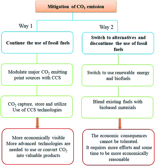
There are two ways to minimize the emission of CO2. First, fossil fuels can continue to be used with the recommendation to use different CO2 capture, storage, and utilization methods. Second, people can switch to using alternative clean energies and biomaterials.6 However, this way seems economically unviable as people cannot bear the high cost of such technologies. So, a combination of both can be a good option until new technologies are developed, Fig. 1.
3. Strategies for minimizing CO2 emissions
The strategies that can be used to minimize anthropogenic CO2 emissions include:7(i) Decreasing the production of CO2 with the use of the sources of renewable energy, such as solar, hydro, and wind, and by increasing energy efficiency.
(ii) Extracting produced CO2 from the climate by reforestation and geological storage in deep-sea sediments and underground storage.
(iii) Converting and utilizing CO2.
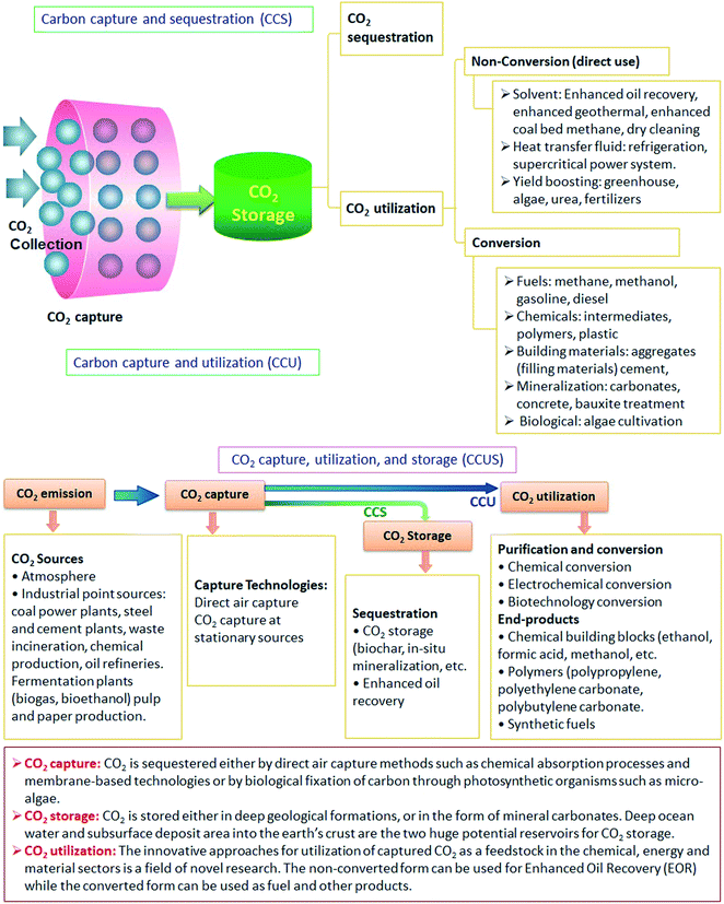
In Fig. 2, several of the crucial procedures are displayed. The chemical sector, for example, has a growing demand for carbon, as does the desire to reduce its reliance on fossil fuels. This, combined with the desire to reach net-zero emissions in the future, has sped up feedstock development. As a result, the industry is aggressively developing carbon capture and utilization (CCU) technology to utilize CO2 as a feedstock alongside new generations of bio-based feedstocks and improved recycled raw materials. In recent years, several encouraging advancements have been made, and commercial items such as cosmetic Plastic Bottles manufactured from waste CO2 are now accessible.
4. CO2 sequestration
Carbon sequestration is capturing, securing, and storing CO2 from the atmosphere. The goal is to prevent CO2 from warming the atmosphere by stabilizing it in both solid and dissolved forms. The method has great potential for cutting CO2. There are two basic forms of carbon sequestration; geological and biological.Generally, sequestration can be done in three different ways: post-combustion capture, pre-combustion capture, and oxy-combustion. In addition, many other separation methods, such as gas phase separation, absorption into a liquid, and adsorption on a solid, as well as hybrid procedures like adsorption/membrane systems, are being researched. As companies move to restorative farming practices, they use the aforementioned procedures to collect the carbon emissions from power plants, factories, fuel-burning enterprises, and new generation animal production facilities.
Storage of CO2 in vegetation, such as grasslands or forests, as well as in soils and oceans, is known as biological carbon sequestration. While the process of storing CO2 in underground geologic formations, such as rocks, is known as geological carbon sequestration. Classically, CO2 is extracted from an energy-related source, such as a power plant or a natural gas processing facility, or an industrial source, such as steel or cement production, and then injected into porous rocks for long-term storage. Carbon capture and storage may allow utilizing fossil fuels until another energy source is introduced on a large scale.
New ways of technological carbon sequestration are explored to remove and store CO2 from the atmosphere using innovative technologies. Direct air capture of CO2 can be done directly from the air using advanced technology plants. By developing novel types of chemicals that are capable of identifying and trapping carbon dioxide from the air, scientists are building molecules that can alter the shape. The engineered molecules act as a filter, only attracting CO2. It is highly of interest to have efficient methods for the CO2 removal and utilization of a resource for several applications. This includes the use of CO2 as a raw material to produce graphene.
5. CO2 capture and separation technologies
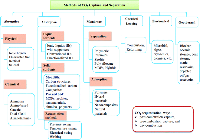
Fig. 3 depicts the procedures and materials utilized for CO2 capture and separation. Briefly, various methods were applied, including absorption, adsorption, separation, membrane, cryogenic distillation, chemical looping, and geothermal and biochemical technologies. CO2 separation can be achieved by ionic liquid membranes, polymeric membranes, and MOF mixed matrix membranes. CO2 capture can be achieved using biological separation/fixation techniques such as microalgae, bacteria, and their enzymes.One of the main CO2 separation technologies that can be applied to isolate the CO2 from the fuel gas stream prior to transportation is absorption which can be done using liquid or solid sorbents. Liquor sorbents are absorbed to separate the CO2 from the flue gas. The sorbent can be regenerated through a stripping or regenerative process by heating or depressurization. CO2 absorption can be performed by common solvents, ionic liquids, deep eutectic solvents, phase-change ionic liquids, solvents modified with nanoparticles, encapsulated liquid sorbents, novel gas–liquid contactors, and mini- and micro-channels, and rotating packed beds.
Adsorption using a solid sorbent binds the CO2 on its surfaces. CO2 adsorption can be performed by carbonaceous materials and nanomaterials, conventional and nanosized zeolites, functionalized sorbents, and swing technologies. Large specific surface area, high selectivity, and higher generation ability are the main criteria for sorbent selection. Another separation method is chemical looping combustion, in which a metal oxide is used as an oxygen carrier instead of using pure oxygen directly for the combustion, as in the case of oxyfuel combustion. During the process, the metal oxide is reduced to metal while the fuel is oxidized to CO2 and water. In membrane separation, various membranes can allow only CO2 to pass through, while excluding other flue gas components. Hydrate-based CO2 separation is a new technology by which the exhaust gas containing CO2 is exposed to water under high pressure forming hydrates. The CO2 in the exhaust gas is selectively engaged in the hydrate cages and is separated from other gases. Cryogenic distillation is a gas separation process using distillation at very low temperatures and high pressure. It is similar to other conventional distillation processes except that it is used to separate components of gaseous instead of liquid. Many adsorption procedures are used to achieve CO2 separation based on regeneration methods. This includes (1) vacuum as well as pressure swing adsorption (VSA and PSA), (2) temperature swing adsorption (TSA), (3) electric swing adsorption (ESA), (4) simulated moving beds (SMB), and (5) purge displacement.8,9
Organic cage frameworks (OCFs), pCage-1, and pCage-2 with controlled porosity synthesized from bicyclooxacalixarene cages were reported to have high CO2 adsorption capacities and adsorption selectivity of CO2/N2, that can be the reason for the introduction of N-doped triazine unit.10 A cross-linked organo-magnesium complex (MTF-Mg) has been reported for selective CO2 adsorption over N2.11 The CO2 preferential adsorption arises from its strong interaction with the exposed magnesium atoms.
In addition, porous organic polymer (HAT-TP) synthesized through a condensation reaction to introduce hexaazatriphenylene (HAT) units to triptycene (TP)-based microporous polymer was reported as an effective recyclable catalyst for chemical conversions of CO2 to cyclic carbonates with epoxide.12
In brief, CO2 capture technologies include:
➢ Pre-combustion: in this process, the fuel is pretreated before combustion.
➢ Post-combustion: this process removes CO2 from the flue gas after combustion.
➢ Oxyfuel combustion: in which oxygen, instead of air, is used for combustion.
Most promising capture technologies include capture at large point sources, which is the extraction of carbon dioxide from the flue gases of industrial sources (e.g., power plants, cement, or steel factories). Direct air capture requires more energy than direct capturing CO2 in flue gases. In addition, capturing the CO2 emitted by bioenergy production can reduce the atmospheric concentration of CO2. The general process is called bioenergy with carbon capture and sequestration.
6. CO2 storage
The CO2 capture and separation are followed by CO2 transportation into the storage location. CO2 storage is the last step in the CCS chain. CO2 storage can be implemented in different modes classified into natural and man-made modes of storage. Natural modes include terrestrial sequestration, while man-made storage includes storage in geologic formations. The storage strategies include:Oceanic underground geological storage is considered the most viable sequestration strategy. In comparison to carbonation and oceanic storage, geological storage is preferable due to several factors, including economic considerations, site accessibility (in the case of ocean and mineral sequestration), and associated worries about the security of the stored CO2 and detrimental environmental effects of mineralization and ocean storage. There are several potential geological storage options, including saline aquifers, depleted oil and gas reservoirs, unmineable coal seams, basalt formations, organic-rich shales, hydrate storage of CO2 within the subsurface environment, and CO2-based enhanced geothermal systems.
Deep ocean storage includes the CO2 injection into deep ocean water. The main proposed approaches for ocean storage are based on the direct dissolution of CO2 into the seawater.
Mineralization or mineral carbonation: in this strategy, the captured CO2 is sequestered through the process of mineralization, where CO2 is reacted with alkaline earth metal oxides or hydroxides, such as calcium-and magnesium-rich minerals, to produce stable carbonates.13
Terrestrial sequestration is the capture of CO2 from the atmosphere and storing of it in soils and vegetation. CO2 removal from the atmosphere through photosynthesis and prevention of the emission of CO2 from terrestrial sources are the mechanisms for terrestrial storage.14
7. CO2 utilization
The scientific community opposes CO2 capture and storage (CCS) because of long-term liability matters, limited cost-effective storage capacity, the probability of leakage, and public acceptance of onshore storage locations.15 At the same time, deep ocean sequestration would instantly influence lowering pH, enhancing water acidity, and potentially causing ecosystem imbalance.16Carbon capture and utilization (CCU) is a viable alternative to CCS that is gaining traction owing to sustainable progress and is thought to be a long-term solution to the CO2 problems. CCU explores the use of CO2 in applications other than storage. CO2 is a vital raw material for products that continue to require carbon sources. This is because it provides their structure and properties (carbon-containing chemicals). Another reason is using carbon-free energy carriers, such as electricity or hydrogen. CO2 is one of the few carbon alternative sources to fossil fuels. The chemical feedstocks,17 refrigerants,18 cleaning liquids,19 solvents media,20,21 inserting agents, and packing gas are examples of CO2 use attempts that have been demonstrated in recent years.
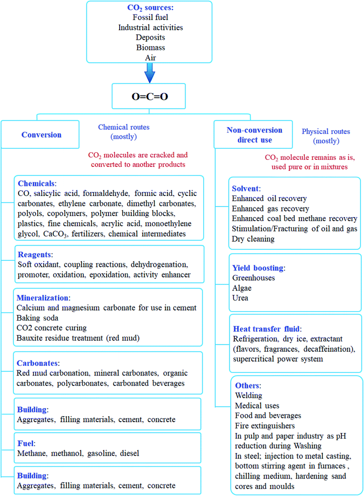
CO2 utilization can be classified into non-conversion utilization (direct use) and conversion utilization, Fig. 4. The entire CCU process can be broken down into two steps:
• The initial step in CCU is the capture of CO2 and separation at the production source.
• The next step is CO2 utilization performed by (i) non-conversion process to use CO2 as a solvent, a working fluid, and a heat transfer agent or by (ii) conversion process to use it as a feedstock for the production of fuels, chemicals, and polymers, Fig. 3. The advantages and disadvantages of some of the potential technological ways of CO2 use are listed in Table 1.
| Technology | Description | Advantages | Disadvantages |
|---|---|---|---|
| (i) Non-conversion | |||
| Desalination | CO2 is combined with brine at high temperature and pressure forming hydrates, which may then be extracted to reveal clean water | ➢ Produces potable water or treats water that has been contaminated by a procedure | ➢ Costs of power and equipment, however, similar to existing water treatment substitutes |
| ➢ Enables a revenue stream or cost offset in a system that has already committed to CCS | |||
| Enhanced oil recovery | CO2 is pumped into existing oil wells to boost pressure and reduce oil viscosity, allowing for more oil to be retrieved | ➢ It is a mature technology with permanent storage and a great potential for CO2 utilization, as well as an income source to pay the costs of carbon capture | ➢ Facilitates further fossil fuel use, producing more CO2 |
| Enhanced geothermal systems | Supercritical CO2 is used to transmit geothermal heat or to create electricity directly using a supercritical CO2 turbine | ➢ Improves the efficiency of a renewable energy source and | ➢ It takes a long time for a product to be commercialized |
| ➢ Provides long-term storage | ➢ Transporting supercritical CO2 is expensive | ||
| ➢ A geothermal site requires a grid connection | |||
| Enhanced coal bed methane | CO2 is pumped into partially depleted coal seams, where it is absorbed by coal, causing methane to be displaced to the surface, where it can be recovered and used as a fuel | ➢ Methane may replace more carbon-intensive fuel sources | ➢ CO2 adsorbed in coal might cause it to swell and impede routes, causing methane recovery to be hampered |
| ➢ It is with permanent storage | ➢ A low cost of methane | ||
| ➢ CO2 transportation costs | |||
![[thin space (1/6-em)]](https://www.rsc.org/images/entities/char_2009.gif) |
|||
| (ii) Conversion | |||
| Mineralization | |||
| CO2 mineralization | CO2 reacts with minerals or industrial waste products. This results in new compounds utilized in constructions, as consumer products, or as a substitute to CCS | ➢ Abundant materials (minerals or industrial wastes) | ➢ To speed up the process, high energy is used |
| ➢ Substitute to CCS | ➢ High material requirements | ||
| ➢ Minerals and processing costs | |||
| Concrete curing | Precast concrete is cured using waste CO2 flue gas. CO2 is kept in the concrete as a non-reactive limestone | ➢ Low cost versus traditional curing | ➢ The product must meet quality requirements |
| ➢ Flue gases can be used directly in the cement industry | ➢ The expense of modifying the curing process | ||
| ➢ Carbon offset opportunity for the cement industry, which produces a lot of pollution | |||
| ➢ A low-carbon consumer item that has the potential to grow beyond its current market | |||
| Bauxite residue carbonation | The alkalinity of aluminum mining slurry is reduced by CO2 | ➢ Aluminum mine closure and reclamation expenses can be reduced | ➢ Cost of concentrating CO2 |
| ➢ Need access to CO2 | |||
| Biological | |||
| Algae cultivation | CO2 is absorbed by microalgae, which can then be transformed into proteins, fertilizers, and biomass for biofuels | ➢ Competitive source of biofuel | ➢ Algae are sensitive to impurities, pH |
| ➢ Can use flue gas directly | ➢ Cost of controlling growth and drying conditions | ||
| ➢ Can result in permanent storage | ➢ Large area and sunny climate needed for ponds | ||
| ➢ A tonne of microalgae can fix about two tonnes of CO2 | ➢ High energy needs for photobioreactors | ||
| Chemicals | |||
| Liquid fuels – methanol | Methanol is produced by catalytically converting CO2 and hydrogen into methanol, which can be combined with gasoline | ➢ The energy carrier eventually replaces fossil fuels, lessening our reliance on them for transportation and other purposes | ➢ Inefficient process; requires renewable or low emissions energy to have net CO2 abatement benefit |
| ➢ Needs low-cost renewable hydrogen | |||
| ➢ Cost of purifying CO2 | |||
| Liquid fuels – formic acid | Formic acid is made by electro-reducing CO2 in water | ➢ Formic acid is a preservative and antibacterial agent that can be utilized as an energy carrier (with hydrogen as the major fuel) | ➢ Inefficient process; requires renewable or low emissions energy to have net CO2 abatement benefit |
| ➢ Chemistry needs to be perfected | |||
| ➢ Cost of purifying CO2 | |||
| Polymers/chemical feedstock | CO2 is converted into polycarbonates with the use of a zinc-based catalyst | ➢ Flue gas can be used directly; CO2 has a significant potential usage; a wide range of products (plastic bags, laminates, automobiles, medical components, and so on) are possible | ➢ Non-permanent storage; some CO2 can be re-emitted as soon as six months |
| ➢ Existing infrastructure can be employed | |||
| Urea yield boosting | Urea fertilizer is made from ammonia and CO2 | ➢ Process emissions intensity is reduced | ➢ CO2 is re-emitted when urea is broken down as fertilizer |
| ➢ Non-permanent storage | |||
7.1. CO2 non-conversion utilization (direct use)
CO2 can be used directly in several applications such as dry ice, carbonated drinks, fire extinguisher, solvent, refrigerants, process fluids, welding mediums, or in algae farms for photosynthesis. It can also be used in large-scale industries to enhance oil recovery, gas recovery, and geothermal systems indirectly. Also, the direct use of CO2 includes its use as heat transfer fluid in refrigeration, power systems, and other industries. Another example of CO2 non-conversion utilization is in desalination, where CO2 is combined with brine at high temperature and pressure, forming hydrates, which may then be extracted to reveal clean water.In such uses, CO2 molecules remain pure or dissolved in a mixture and do not react or crack further. However, such direct applications for CO2 are limited in scale and have a small effect on the overall CO2 abatement.22
7.2. CO2 conversion utilization
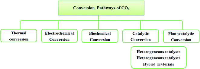
A potential solution to environmental issues like global warming and the energy crisis is the conversion of CO2 to sustainable and green solar fuel. Technologies like CO2 capture, storage, and usage provide appealing methods to lower CO2 emissions. Although CO2 can be effectively separated via CO2 collection and storage, converting CO2 into chemicals and fuels is more practical. It converts CO2 into crucial molecules like carbonate, methanol, salicylic acid, and other substances.In the conversion process, a carbon–carbon bond or a carbon–hydrogen bond has to be established. Such bond formation requires energy input to activate CO2 or the other substrates such as reductive coupling. Inappropriately, the carbon–oxygen double bond is very stable (energy of CO2 750 kJ mol−1) compared with C–H and C–C chemical bonds (430 and 336 kJ mol−1). Commonly, chemical fixation of CO2 requires: (i) high input of energy to perform reaction activity of substrate (unsaturated compounds, small-ring compounds, and organometallic compounds) and (ii) high reaction temperature and pressure. There are several pathways for CO2 conversion. These can be classified as shown in Fig. 5.
In brief, the CO2 conversion reactions can be categorized into two classes:
(i) The first class includes the reactions that do not need a substantial amount of external energy. Hence, the reaction occurs by attaching the CO2 molecule to the other reactant. These reactions are usually called carboxylation reactions. Consequently, this class involves the production of carboxylates and lactones (RCOOR), carbamates (R1R2NCOOR3), ureas (RRNCONRR), isocyanates (RNCO), and carbonates (ROC(O)OR).
(ii) The second class includes the reactions that produce reduced forms of CO2. Such reduction reactions require a significant amount of external energy. They involve products including; HCOO− (formates), [C(O)O]22− (oxalates), H2CO (formaldehyde), CO, CH3OH, CH4, and C2H4. The external energy needed in these reactions is supplied as heat, electrons, or irradiation/photons to break the bonds in CO2. Such processes are named thermal, electrochemical, and photochemical, respectively. Consequently, catalysis, and high temperature and pressure, are required for lowering the energy barrier toward the formation of C1-building block chemicals, for instance.23,24
Such catalytic process of CO2 includes the formation of chemicals such as urea, methane, methanol, formic acid, formaldehyde, ethylene carbonate, dimethyl carbonate, cyclic carbonates, salicylic acid, cyclic carbonates, polymer building blocks, and polycarbonates.
In bioelectrochemical processes, CO2 is converted with the support of microorganisms directly in one step. However, it can also be converted with separate production of H2 in a two-step process. In the first step, hydrogen is produced, then in the second step, hydrogen and CO2 are fed to a bioreactor containing anaerobic methanogenic species for methane production.
Due to the limitations of natural CO2 fixing pathways, synthetic CO2 fixation routes have been developed at levels of in silico prediction, in vitro testing, and in vivo implantation of a synthetic CO2 fixation pathway. Multiple criteria are considered while designing a synthetic CO2 fixing pathway. Oxygen-tolerant and kinetically fast carboxylases are considered to incorporate into the pathways. The undesired side reactions are kept at a minimum. After passing the topological, energetic, and kinetic assessment, the resulting designed pathway is anticipated to have quick overall pathway kinetics, high flux, and improved performance compared to natural CO2 fixing pathways.
The photosynthetic recycling of CO2 can be used to produce products such as 2-methyl-1-butanol, isobutyraldehyde, and isobutanol, ethanol, butanol, malate, formate, lipids, sugars (hexose, pentose, and triose), biomass, succinate, limonene, isopropanol, acetic acid, isobutanol, and 3-methyl1-butanol, succinic acid, isobutyraldehyde, 1,3-propanediol.26
Examples of CO2 catalytic conversion include CO2 reforming of CH4, CO2 hydrogenation to methanol, formation of dimethyl carbonate from CO2 and methanol, formation of cyclic carbonate from CO2 and epoxide, and formation of cyclic carbonate from CO2 in the presence of ammonium salt, and the reaction of CO2 and propylene glycol.28
Catalytic conversion of CO2 can be used to form hydrocarbon and non-hydrocarbon fuels. Because of the high stability of CO2 molecule  , CO2 conversion into valuable products requires high energy depending on the downward steps for 4+ oxidation state of carbon. CO2 conversion to HC fuels involves a high energy process, where the C-oxidation state is +2 or lower for possible production of compounds such as HCOOH, H2CO, CH3OH, CH4, and other HCs.29
There are two ways to convert CO2 into hydrocarbon-based fuels; (1) transformation using classical Fischer–Tropsch synthesis [Ramirez] through reverse water-gas shift (RWGS) reaction followed by HC cracking, isomerization and aromatization, (2) CO2 transformation into methanol (MeOH) followed by the MeOH conversion to HC. The CO2 is first converted via the Fischer–Tropsch synthesis and then followed by coupling with the Fischer–Tropsch catalyst system containing zeolite. This is to allow production distribution and selectivity to olefins and or aromatic. Similarly, combining the CO2 with MeOH catalyst system, i.e., zeolite, can also allow the generation of useful chemicals via the CO hydrogenation.30
Catalysts such as metals and their oxides, carbon nanostructures, metal–organic frameworks (MOFs), and polymer functionalized materials have been reported for CO2 conversions.31 For CO2 reduction, the one-electron reduction is endothermic and produced (CO2˙) is highly reactive. Electrochemical potentials of possible CO2 reduction reactions in aqueous solutions for the production of different chemicals and hydrocarbon fuels are in equations:
 | (1) |
| CO2 + 2H+ + 2e− → HCOOH, E° = −0.61 V | (2) |
| CO2 + 2H+ + 2e− → CO + H2O, E° = −0.53 V | (3) |
| CO2 + 4H+ + 4e− → HCHO + H2O, E° = −0.48 V | (4) |
| CO2 + 6H+ + 6e− → CH3OH + H2O, E° = −0.38 V | (5) |
| CO2 + 8H+ + 8e− → CH4 + 2H2O, E° = −0.24 V | (6) |
| 2H+ + 2e− → H2, E° = −0.41 V | (7) |
| 2H2O → O2 + 4H+ + 4e−, E° = +0.81 V | (8) |
Fig. 6 lists several reactions for the transformation of CO2 into products that are commercially valuable.32
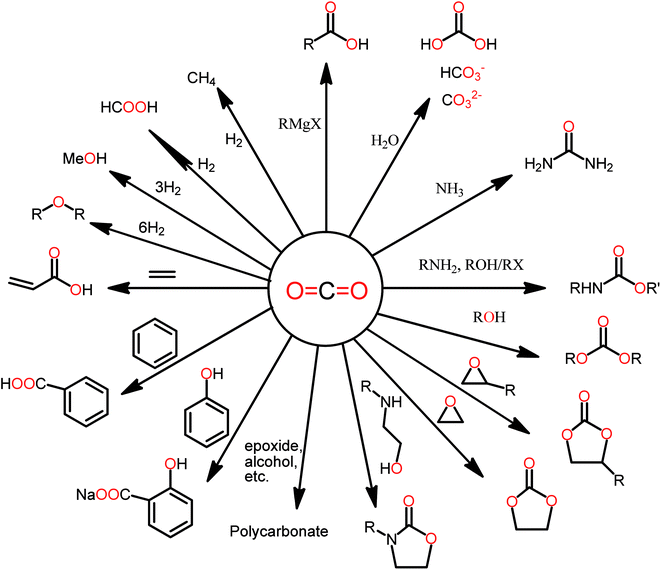 | ||
| Fig. 6 Directions of the CO2 chemical transformation to various chemicals.3 | ||
7.2.4.1. Nanomaterials used for CO2 catalytic conversion. The general classification of the materials and nanomaterials used for CO2 conversion can be listed in Fig. 7. These materials can be prepared, modified, and used individually or prepared in a hybrid or combination of two or more chemicals. Hybridization of two or more types of these materials may further improve efficiency. For example, carbon materials like graphene, graphene oxide (GO), reduced GO, carbon nanotubes, and graphitic carbon nitride (g-C3N4) are commonly used for CO2 applications. By varying the precursor, performing post-synthetic functionalization, and modification with metal nanoparticles or polymeric branches, the electronic band structures of the carbon nanomaterials and their light absorption features can be tuned, therefore, enhancing the CO2 conversion and making them attractive for CO2 applications.33–35
Solid substrates are functionalized or modified with amines and ionic liquids36,37 to have more affinity toward CO2. Nevertheless, polymers such as amidine and guanidine-based polymers, poly(ethylene-imine), poly(ether imide), and poly(ionic liquid)s (PILs) interact more with CO2.38 Other polymers, including polystyrene, polysulfone, or poly(ether-b-amide-6), can be utilized due to their controllable porosity, good CO2 permeability, and selectivity.
Porous organic polymers prepared from specific multidentate organic building blocks are good candidates for CO2 applications.39,40 However, polymerization conditions play a key role in their porosity. In addition, cross-linking of polymers is optimized and controlled to get macroporous (>50 nm), mesoporous (2–50 nm), and microporous (<2 nm) materials. This can also impact the pore volume and surface area, which are important parameters affecting the affinity toward CO2.41
Another class of materials is the inorganic materials which can be synthesized with good morphology and high surface area. Examples include spherical nanoparticles, nanowires, nanocubes, and nanosheets. These materials can be easily prepared with controlled properties. For instance, nanoparticles of numerous shapes display various efficiencies for identical catalytic processes owing to the exposure of several crystal facets.42–44 Metal such as palladium, gold, silver, and copper are the most efficient. With the ability to stabilize the reaction intermediates, metals such as copper are outstandingly active for CO2 reduction to hydrocarbons. However, in some cases, palladium, gold, and silver form CO.45,46 MOFs are another class of materials that showed excellent performance in CO2 applications owing to their crystallinity and high surface area.47,48 Such materials with crystals show high internal cavities interconnected mainly by small channels to play a key role in several CO2 applications.49,50 Heterogeneous catalytic conversion of CO2 to chemicals and fuels is gaining particular interest because of its better stability, durability, simplicity in separation, handling, and simpler reactor design.
7.2.4.2. Homogeneous and heterogeneous metal complex-based catalysts. Homogeneous and heterogeneous metal complex-based catalysts are used for the electroreduction of CO2, Fig. 8. In homogeneous catalysis, the metal complex acts as a redox shuttle between the electrode and CO2. Mostly, the catalyst is in a more highly reduced state due to its acceptance of electrons from the electrode. As a result of the reduction, the catalyst transfers electrons to CO2 in the solution and returns to its initial state, resulting in an indirect electrolysis reaction.31 Catalysts are often single atom transition-metal complexes stabilized by ligands in environments that tune the redox potentials of the catalyst. In the stable coordination environments found for typical Ir and Ru metal complexes, there is often a high catalytic selectivity after optimization in the design of the catalyst. However, the difficulties of catalyst recovery after catalytic cycles with considerable energy demands from distillation, filtration, or crystallization to recover the catalyst is a significant impediment in large-scale synthesis.
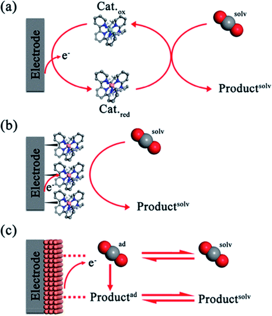 | ||
| Fig. 8 Reduction of CO2 by various catalytic mechanisms: (a) homogeneous, (b) immobilized, and (c) heterogeneous way in an electrocatalytic film.52 | ||
Catalyst immobilization in surface or electrochemical reactions combines the benefits of homogenous catalysis and selectivity with the capacity to reuse the catalysts. With the reduction of CO2 as our primary goal, we devised many techniques, including polymerization, noncovalent surface binding, and surface-chemical binding, to make chemically modified electrodes.51 Surface binding facilitates electron transfer from the electrode to metal complex catalysts on the surface. The electrochemical reduction of CO2 using heterogeneous catalysts with high surface area is an appealing method. Nanostructured catalysts can produce much improved reactive surfaces with a significant portion of the reactive sites available for catalysis compared to traditional electrodes.
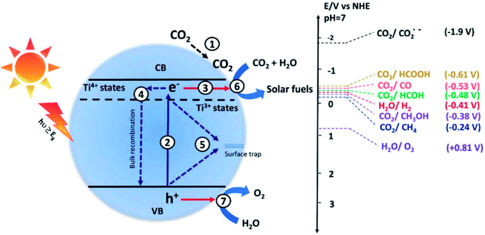 | ||
| Fig. 9 Steps of photocatalytic CO2 conversion. The absorption of light energy equal to or greater than the bandgap (Eg) results in the excitation of the electrons from the valence band (VB) to the conduction band (CB), leaving behind holes in the VB. The electrons and holes promote the reduction and oxidation of the reactant molecules.53 | ||
The influencing factors for CO2 photocatalytic reactions,54,55 rate-limiting steps,56 thermodynamic and kinetic requirements,57 and reaction processes58,59 have all been reviewed in several reports. For example, the adsorption of reactants on the surface of the catalysts is critical in heterogeneous catalytic reactions, and it is often regarded as the first step in initiating the reaction. CO2 adsorption on photocatalysts is the first stage in CO2 photoreduction, and the amounts and states of CO2 adsorption on photocatalysts can have a big impact on CO2 reduction processes, efficiency, and product selectivity.60,61 This component has previously been disregarded. The number of papers looking at the impact of CO2 adsorption on CO2 photoreduction has increased in recent years. There are, however, few assessments that summarize these attempts.
Generally, the mechanisms for CO2 photoreduction can be explained in different ways.62–65 These mechanisms can be summaries in the steps including:
Step 1: CO2 and H2O diffuse into the photocatalyst surface
Step 2: CO2 and H2O do move along the photocatalyst surface by surface diffusion to occupy the active sites
Step 3: Light absorption and formation of electrons holes on the surface of the photocatalyst
Step 4: Interaction between adsorbed reactants and charged particles and then recombination of charged particles
Step 5: Desorption of the formed products
7.2.5.1. Photocatalysts requirements. Catalysts should be with: (i) photosensitizer component (to initiate photochemical one-electron transfer), such as organic compounds semiconductors and metal complexes, and (ii) catalyst (to convert one-electron transfer into a multi-electron reduction of CO2), such as complexes, metal particles, and enzymes. Excellently designed photocatalysts (rhenium(I) complexes) can fill both roles. The photocatalytic efficiency can be evaluated by: (i) product selectivity, (ii) quantum yield = (product/mol)/(absorbed photons/einstein), (iii) the stability of the photocatalyst given by turnover number (TON) = (product/mol)/(photocatalyst/mol or unit mass), (iv) the photocatalytic cycle speed given by turnover frequencies (TOF) = TON/(reaction time/min).
7.2.5.2. Homogeneous catalysts. Homogenous redox photocatalysts consist of a light-harvesting unit (photosensitizer) and two catalytic sites. One site is for the oxidation process, where a donor provides the electrons, and the other is the reduction site, where the electrons are transferred to an acceptor. Sometimes, the photosensitizer works as photosensitizer and reduction site.66
Visible light absorption by the photosensitizer unit leads to the excited state. Commonly used photosensitizers for CO2 reduction are ruthenium (polypyridyl)-and (bipyridyl)-rhenium(I) complexes (2.1 Chromophores). So, the light absorption gives rise to a single metal to ligand charge transfer (1MLCT), which produces a triplet excited state (3MLCT) by inter-system crossing. This 3MLCT state has different redox properties than the ground state. Owing to this state's reducing properties, direct interaction with an acceptor can lead to the one-electron oxidized ground state of the photosensitizer via oxidative quenching. In terms of CO2 reduction, reductive quenching is the more important process. With an electron from the oxidation site, a ground state of electron reduced species is formed, capable of transferring electron to the reduction site to recover the d6 neutral ground state of the photosensitizer.67
When exposed to light radiations of suitable frequencies, the ruthenium-or iridium-based complexes convert CO2 into CO or formate.4 A series of anthracene-substituted mononuclear and dinuclear rhenium complexes have been reported for photocatalytic CO2 reduction showing a good TON value and long life.5 The anthracene moiety also functions as a sterically bulky group that may inhibit deleterious intermolecular catalyst deactivation pathways.
Examples of the multi-component system include ruthenium(I) diimine photosensitizers, rhenium(II) diimine, photosensitizer, and organic photosensitizers.41 Moreover, some supramolecular photocatalysts are also used, such as Ru(II)–Ni(I), Ru(II)–Co(III), and Ru(II)–Re(I). An example of the selective catalytic reduction site for the photoreduction of CO2 over rhenium(I) systems is given in Fig. 10.28
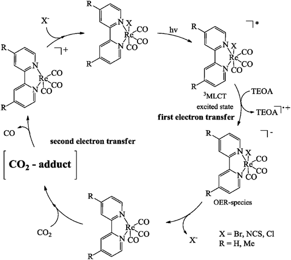 | ||
| Fig. 10 Catalytic cycle for the photoreduction of CO2 with (bipyridyl)Re(CO)3X complexes by Hawecker et al.68 | ||
7.2.5.3. Heterogeneous catalysts. Several heterogeneous catalysts have been developed, including metal-supported catalysts, perovskites, and solid solution catalysts.69 The heterogeneous catalyst consists of metal, supports, and promotors. Precious metals (Pt, Rh, or Ru) are known to have high activity and durability and are resistant to coke deposition, although at a high price. The precious metal-based catalysts show high activity in spite of the very small amount of metal catalyst used.
Non-precious metals (Ni or Co) have been widely investigated as well. Non-precious metals such as Ni or Co have been used more for DRM due to their low price and abundance.70 Ni catalysts have shown a level of activity comparable to precious metals. Alloyed metal catalysts are widely used because they have a different electronic structure than monometallic materials. Monometallic Ni or Fe catalysts have shown poor durability because the monometallic Ni catalyst is easily deactivated by coke deposition, and Fe is not much active for CO2 conversion.
TiO2, BaLa4TiO15, SrTiO3, WO3, NaNbO4, and Zn2GeO4 are a few of the materials that show promise for use in these applications. Most of these inorganic semiconductors have good structural controllability and stability (the morphology, size, and surface). Titania-based materials, including 1-D (TiO2 nanowires, nanorods, nanobelts, and nanotubes), 2-D (TiO2 nanolayers and nanosheets), 3-D, and hierarchical nanostructures, are the most commonly employed catalysts.16 Enhanced efficiency is attributed to factors such as high surface area, good photogenerated-charges separation, directional charge transport, enhanced light-harvesting owing to light trapping/scattering, and low photon influence, considering the configuration and geometry of the photocatalysts. Semiconductors such as ZnO, CdS, GaP, SiC, WO3, Ga2O3, GaP, InTaO4, MgO, ZrO2, BiVO4, and ATaO3 are also used. Semiconductors with more negative CB potentials convert CO2 to CH3OH. Water worked as a reductant since no reducing reagents were introduced into the reaction solutions.71,72
For example, it was reported that AgI/GCN nanocomposite's charge separation process follows the double-transfer mechanism (conventional charge separation mechanism) and Z-scheme process.73 Upon irradiation, the AgI and GCN material's VB electrons are excited to CB. Therefore, the CO2 photoconversion occurs at the surface of AgI if the double charge transfer mechanism is employed (Fig. 11a). However, when the Z-scheme mechanism is adopted, the photoconversion of CO2 occurs on the surface of GCN because the CB value of GCN (−1.12 eV vs. NHE) is more negative than the standard reduction potential for the formation of O2−, methane, ethanol and acetone, Fig. 11b.
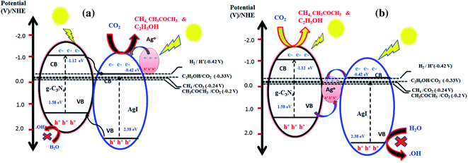 | ||
| Fig. 11 Charge separation mechanism for photocatalytic conversion of CO2 over AgI/GCN composite. (a) Double charge separation mechanism; (b) Z-scheme mechanism.73 | ||
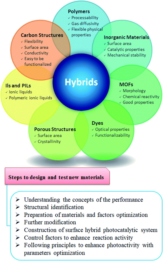
7.2.5.4. Hybrid nanocatalysts. Hybrid materials are composites made by a synergistic combination of organic and inorganic components at the nanometer or molecular level. New properties are created by new electron orbitals formed between them. Hybrid materials such as a photocatalyst consisting of photosensitizer (CdSe quantum dots) and catalyst (Pt/TiO2) were reported.74 CdSe quantum dots show a negative shift of CB energy where electron injection into titania can proceed under visible light in an aqueous media forming CH4 and CH3OH. Nanoparticles supported on carbon nanotubes, g-C3N4, graphene nanosheets, and carbon dots are used for CO2 photoreduction under vis-light into CO.75–77 The influence of dye-based organic linkers on CO2 photoreduction efficiency has been reported using UiO-67. Re3-MOFs displayed high photocatalytic activity. When Ren-MOFs and Re3-MOFs were coated with silver nanoparticles, the efficiency was seven times enhanced, Fig. 12.78
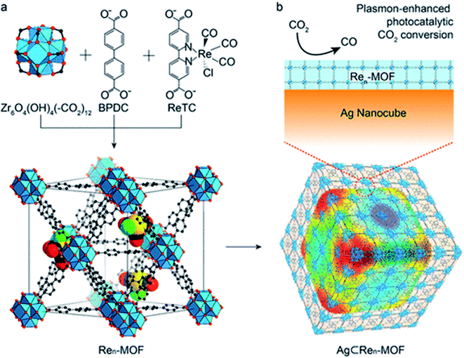 | ||
| Fig. 12 Structures of Ren-MOF and Ag-Ren-MOF for plasmon-enhanced photocatalytic CO2 conversion (a) and mechanism of conversion (b).78 | ||
Covalently bonded microporous organic polymers (MOPs) showed high physical and chemical stability. Cooper's group reported on several monomers synthesizing pyrene-based conjugated microporous polymers with 1.94–2.95 eV band gaps, exhibiting high photocatalytic activity.79 Covalent triazine frameworks (CTFs) are a distinguished subclass of contemporary high-performance nanoporous materials. CTFs with aromatic triazine linkages are constructed by covalently linked light elements (C, N, and H) and boast high porosity, high nitrogen content, and good thermal/chemical stability. Furthermore, a triazine ring connected with electron-rich units can easily form p–n heterojunction via the conjugated structure, imparting superior nature to conjugated CTFs, particularly in terms of bandgap tunability and rapid electron separation rates.80,81
8. Pilot-scale projects and commercialization
Several well-known industries have expanded their funding for CCUS work. Also, various demonstration initiatives at the pilot scale are underway.82 Examples are:• CarbFix in Iceland for CO2 capture from geothermal fluid and air.
• Drax in the UK for CO2 capture from biomass power generation.
• STEPWISE in Sweden for sorption-enhanced water gas shift separation testing in the iron as well as the steel industry.
• CIUDEN in Spain for CO2 storage.
• Geothermal plants for CCUS in Croatia for electricity generation from geothermal hot brine.
CCS is projected to play a key role in achieving global warming goals and turning CO2 into useful goods.83,84 As a result, several technologies are being developed to capture, transport, store, and utilize CO2. Typically, technological development proceeds in stages: (i) bench or laboratory size, (ii) pilot scale, (iii) demonstration scale, and (iv) commercial scale.
These steps can be easily classified into numerous technology readiness levels (TRL), Fig. 13. At the TRL 3, TRL 6, and TRL 7 development stages, there is a glut of technology. Beyond TRL 3, improving a technology necessitates further research money, but methods beyond TRL 5 and TRL 7 necessitate major financial commitment and commercial interests, for example, in the case of some polymeric membranes. The following sections of this article go into greater detail about the technical development of the various CCS technologies.
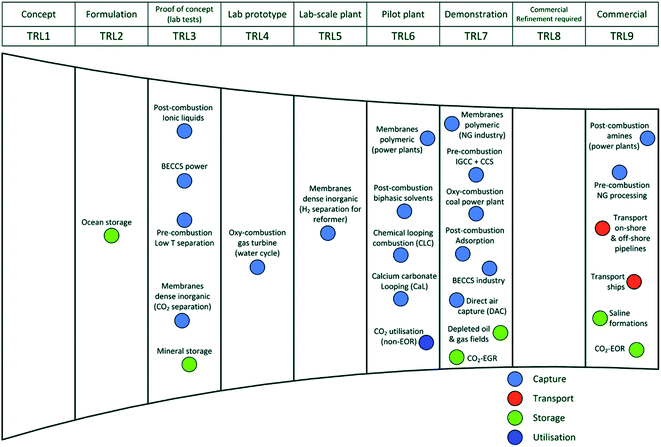 | ||
| Fig. 13 Carbon collection, storage, and utilization technologies progressing in terms of technology readiness (TRL).85 | ||
9. CO2 use market
Although it is difficult to assess the future market of CO2 uses, there are some areas and applications of CO2. These can be listed as:9.1. CO2-derived fuels
The carbon in CO2 can be used to produce fuels that are in use today. The process involves using CO2 in combination with hydrogen, which is highly energy-intensive to produce carbon-containing fuels that are easier to handle and use than pure hydrogen. Examples are methane, methanol, gasoline, and aviation fuels.9.2. CO2-derived chemicals
The carbon and oxygen in CO2 are promising to be used as an alternative to fossil fuels in producing chemicals, and materials including plastics, fibers, and synthetic rubber. Converting CO2 to methanol and methane is the most technologically mature pathway.9.3. CO2 to building materials
CO2 can be used to produce building materials to replace the water in concrete. It is called CO2 curing or as a raw material in its constituents, cement, and construction aggregates. This process involves the reaction of CO2 with calcium or magnesium to form low-energy carbonate molecules, the form of carbon that makes up concrete. While incorporating CO2 in the manufacture of cement is still in its early stages of development, CO2-cured concrete is one of the most established and promising applications of CO2 utilization.Construction aggregates, tiny particles used in building materials, can be made by combining CO2 with industrial or waste products from power plant activities. These include coal fly ash and iron slag, which would otherwise be heaped or kept in landfills, Fig. 14.
 | ||
| Fig. 14 CO2 conversion pathways into CO2-derived building materials (building aggregates or CO2-cured concrete). | ||
9.4. Crop yield boosting
CO2 can be utilized to increase the yields of biological processes, such as algae growth and greenhouse crop cultivation. The most developed use for increasing yields is using CO2 with low-temperature heat in industrial greenhouses.10. Conclusion and future perspective
In summary, one of the key issues facing our world is the rapid increase in atmospheric carbon dioxide (CO2) concentrations. As a result, considerable interest has been in regulating CO2 emissions and lowering atmospheric CO2 concentrations to avoid a worldwide disaster. To reduce CO2 emissions, various approaches have emerged including:➢ Developing and converting to environmentally friendly energy sources;
➢ Improving energy efficiency and utilizing current processes;
➢ CO2 collection and sequestration;
➢ Converting CO2 to valuable products.
There has recently been a surge in interest in capturing CO2 emissions and either permanently immobilizing them or chemically converting them into useful goods. This has prompted the creation of many strategies, approaches, and techniques aimed at reducing CO2 levels through green energy alternatives as well as capturing and converting CO2 into value-added products.
The use of CO2 in commercial technology is based mostly on a trade-off between performance and environmental benefits.
Overall, this review is based on containing and utilizing CO2 using organic–inorganic hybrid materials. The range of potential CO2 uses involves direct use, by which CO2 is not chemically altered (non-conversion), and the use of CO2 by transformation, via multiple chemical and biological conversion processes to fuels, chemicals, and building materials. The strategy/technologies come under CO2-Capture Utilization and Storage (CCUS). CCUS is far better than CCS because the former utilizes/transforms CO2 into valuable products like ethylene, ethanol, methanol, formic acid, and formaldehyde. The transformations can be achieved using various materials, such as organic–inorganic hybrid-nanocomposites. Contemporary research should primarily focus on sustainable science to immediately address global warming.
The market for CO2 use is expected to increase, with opportunities related to building materials, and as a carbon source for fuels and chemicals. However, some key factors affect the future market for CO2-derived products, including scalability, competitiveness and climate benefits, and the visibility of the technologies.
Conflicts of interest
There are no conflicts to declare.References
- IPCC, 2014: Climate Change 2014: Synthesis Report. Contribution of Working Groups I, II and III to the Fifth Assessment Report of the Intergovernmental Panel on Climate Change, IPCC, Geneva, Switzerland, 2014 Search PubMed.
- A. J. Nathanael, K. Kannaiyan, A. K. Kunhiraman, S. Ramakrishna and V. Kumaravel, Global opportunities and challenges on net-zero CO2 emissions towards a sustainable future, React. Chem. Eng., 2021, 6, 2226–2247 RSC.
- N. MacDowell, et al., An overview of CO2 capture technologies, Energy Environ. Sci., 2010, 3, 1645–1669 RSC.
- S. VijayaVenkataRaman, S. Iniyan and R. Goic, A review of climate change, mitigation and adaptation, Renewable Sustainable Energy Rev., 2012, 16(1), 878–897 CrossRef.
- N. P. Liyanage, W. Yang, S. Guertin, S. Sinha Roy, C. A. Carpenter, R. E. Adams, R. H. Schmehl, J. H. Delcamp and J. W. Jurss, Photochemical CO2 Reduction with Mononuclear and Dinuclear Rhenium Catalysts Bearing a Pendant Anthracene Chromophore, Chem. Commun., 2019, 55(7), 993–996 RSC.
- K. O. Yoro, Numerical Simulation of CO2 Adsorption Behaviour of Polyaspartamide Adsorbent for PostCombustion CO2 Capture, MSc thesis, University of the Witwatersrand, Johannesburg, South Africa, 2017 Search PubMed.
- A. Gulzar, et al., Carbon dioxide utilization: a paradigm shift with CO2 economy, Chem. Eng. J. Adv., 2020, 3, 100013 CrossRef CAS.
- E. J. Granite and T. O'Brien, Review of novel methods for carbon dioxide separation from flue and fuel gases, Fuel Process. Technol., 2005, 86, 1423–1434 CrossRef CAS.
- H. Yang, Z. Xu, M. Fan, R. Gupta, R. B. Slimane, A. E. Bland and I. Wright, Progress in carbon dioxide separation and capture, J. Environ. Sci., 2008, 20, 14–27 CrossRef CAS.
- Z. Wang, Q. Ou, H. Ma, G. Cheng, Q.-P. Zhang, B. Tan and C. Zhang, Molecular Engineering for Organic Cage Frameworks with Fixed Pore Size to Tune Their Porous Properties and Improve CO2 Capture, ACS Appl. Polym. Mater., 2021, 3(1), 171–177 CrossRef CAS.
- K. Pareek, Q. Zhang, R. Rohan and H. Cheng, Highly selective carbon dioxide adsorption on exposed magnesium metals in a cross-linked organo-magnesium complex, J. Mater. Chem. A, 2014, 2, 13534–13540 RSC.
- H. Ma, Z. Wang, Y.-H. Zhao, Q. Ou, B. Tan and C. Zhang, Microporous polymer based on hexaazatriphenylene-fused triptycene for CO2 capture and conversion, Sci. China Mater., 2020, 63, 429–436 CrossRef CAS.
- J. T. Litynski, S. M. Klara, H. G. McIlvried and R. D. Srivastava, An overview of terrestrial sequestration of carbon dioxide: The United States Department of Energy's fossil energy R&D program, Clim. Change, 2006, 74(1–3), 81–95 CrossRef CAS.
- M. Bonchio, M. Carraro, M. Gardan, G. Scorrano, E. Drioli and E. Fontananova, Hybrid photocatalytic membranes embedding decatungstate for heterogeneous photooxygenation, Top. Catal., 2006, 40, 133 CrossRef CAS.
- C. Oltra, P. Upham, H. Riesch, À. Boso, S. Brunsting, E. Dütschke and A. Lis, Public responses to CO2 storage sites: lessons from five European cases, Energy Environ., 2012, 23, 227–248 CrossRef.
- R. L. Newmark, S. J. Friedmann and S. A. Carroll, Water challenges for geologic carbon capture and sequestration, Environ. Manage., 2010, 45, 651–661 CrossRef PubMed.
- T. Sakakura, J.-C. Choi and H. Yasuda, Transformation of carbon dioxide, Chem. Rev., 2007, 107, 2365–2387 CrossRef CAS PubMed.
- A. Pearson, Carbon dioxide—new uses for an old refrigerant, Int. J. Refrig., 2005, 28, 1140–1148 CrossRef CAS.
- W. Dale Spall and K. E. Laintz, A Survey on the use of supercritical carbon dioxide as a cleaning solvent, ed. M. John and P. S. Samuel, William Andrew Publishing, Westwood, NJ, 1998, pp. 162–194 Search PubMed.
- A. Baiker, Supercritical fluids in heterogeneous catalysis, Chem. Rev., 1998, 99, 453–474 CrossRef PubMed.
- A. Laury and J. G. Sebranek, Use of carbon monoxide combined with carbon dioxide for modified atmosphere packaging of pre- and postrigor fresh pork sausage to improve shelf life, J. Food Prot., 2007, 70, 937–942 CrossRef CAS PubMed.
- N. Muradov, Industrial Utilization of CO2: a Win–Win Solution, in Liberating Energy From Carbon: Introduction to Decarbonization, Springer New York, New York, NY, 2014, pp. 325–383 Search PubMed.
- T. Inoue, A. Fujishima, S. Konishi and K. Honda, Photoelectrocatalytic reduction of carbon dioxide in aqueous suspensions of semiconductor powders, Nature, 1979, 277, 637 CrossRef CAS.
- E. Alper and O. Orhan, CO2 utilization: developments in conversion processes, Petroleum, 2017, 3(1), 109–126 CrossRef.
- A. N. Mistry, U. Ganta, J. Chakrabarty and S. Dutta, A review on biological systems for CO2 sequestration: organisms and their pathways, Environ. Prog. Sustainable Energy, 2019, 38, 127–136 CrossRef CAS.
- A. Nisar, S. Khan, M. Hameed, A. Nisar, H. Ahmad and S. Azhar Mehmood, Bio-conversion of CO2 into biofuels and other value-added chemicals via metabolic engineering, Microbiol. Res., 2021, 251, 126813 CrossRef CAS PubMed.
- B. Cornils and W. A. Hermann, Applied Homogeneous Catalysis with Organometallic Compounds, VCH, Weinheim, 1996, vol. 2, p. 1048 Search PubMed.
- J. Ma, N. Sun, X. Zhang, N. Zhao, F. Xiao, W. Wei and Y. Sun, A short review of catalysis for CO2 conversion, Catal. Today, 2009, 148(3–4), 221–231 CrossRef CAS.
- M. D. Porosoff, B. Yan and J. G. Chen, Catalytic reduction of CO2 by H2 for synthesis of CO, methanol and hydrocarbons: challenges and opportunities, Energy Environ. Sci., 2016, 9, 62–73 RSC.
- A. Ramirez, L. Gevers, A. Bavykina, S. Ould-Chikh and J. Gascon, Metal organic framework-derived Iron catalysts for the direct hydrogenation of CO2 to short chain olefins, ACS Catal., 2018, 8, 9174–9182 CrossRef CAS.
- R. Francke, B. Schille and M. Roemelt, Homogeneously Catalyzed Electroreduction of Carbon Dioxide—Methods, Mechanisms, and Catalysts, Chem. Rev., 2018, 118, 4631–4701 CrossRef CAS PubMed.
- G. K. Ramesha, J. F. Brennecke and P. V. Kamat, Origin of Catalytic Effect in the Reduction of CO2 at Nanostructured TiO2 Films, ACS Catal., 2014, 4(9), 3249–3254 CrossRef CAS.
- G. Liu, W. Jin and N. Xu, Graphene-based membranes, Chem. Soc. Rev., 2015, 44, 5016–5030 RSC.
- J. H. Lee, H. J. Lee and J. W. Choi, Unveiling anomalous CO2-to-N2 selectivity of graphene oxide, Phys. Chem. Chem. Phys., 2017, 19, 22743–22748 RSC.
- J. Y. Tang, X. Y. Kong and B. J. Ng, et al) Midgap-state-mediated two-step photoexcitation in nitrogen defect-modified g-C3N4 atomic layers for superior photocatalytic CO2 reduction, Catal. Sci. Technol., 2019, 9, 2335–2343 RSC.
- G. Qi, L. Fu and E. P. Giannelis, Sponges with covalently tethered amines for high-efficiency carbon capture, Nat. Commun., 2014, 5, 5796 CrossRef CAS PubMed.
- T. Endo, D. Nagai, T. Monma, H. Yamaguchi and B. Ochiai, A Novel Construction of a Reversible Fixation–Release System of Carbon Dioxide by Amidines and Their Polymers, Macromolecules, 2004, 37, 2007–2009 CrossRef CAS.
- S. Supasitmongkol and P. Styring, High CO2 solubility in ionic liquids and a tetraalkylammonium-based poly(ionic liquid), Energy Environ. Sci., 2010, 3, 1961–1972 RSC.
- D. Wu, F. Xu, B. Sun, R. Fu, H. He and K. Matyjaszewski, Design and Preparation of Porous Polymers, Chem. Rev., 2012, 112, 3959–4015 CrossRef CAS PubMed.
- P. Bhanja, A. Modak and A. Bhaumik, Porous Organic Polymers for CO2 Storage and Conversion Reactions, ChemCatChem, 2019, 11, 244–257 CrossRef CAS.
- P. Kaur, J. T. Hupp and S. T. Nguyen, Porous Organic Polymers in Catalysis: Opportunities and Challenges, ACS Catal., 2011, 1, 819–835 CrossRef CAS.
- S. Cao, F. Tao, Y. Tang, Y. Li and J. Yu, Size- and shape-dependent catalytic performances of oxidation and reduction reactions on nanocatalysts, Chem. Soc. Rev., 2016, 45, 4747–4765 RSC.
- Y. Tamaki and O. Ishitani, Supramolecular Photocatalysts for the Reduction of CO2, ACS Catal., 2017, 7(5), 3394–3409 CrossRef CAS.
- D. Raciti and C. Wang, Recent Advances in CO2 Reduction Electrocatalysis on Copper, ACS Energy Lett., 2018, 3, 1545–1556 CrossRef CAS.
- R. Shi, G. I. N. Waterhouse and T. Zhang, Recent Progress in Photocatalytic CO2 Reduction Over Perovskite Oxides, Sol. RRL, 2017, 1, 1700126 CrossRef.
- J. Hou, S. Cao, Y. Wu, Z. Gao, F. Liang, Y. Sun, Z. Lin and L. Sun, Inorganic Colloidal Perovskite Quantum Dots for Robust Solar CO2 Reduction, Chem.–Eur. J., 2017, 23, 9481–9485 CrossRef CAS PubMed.
- M. S. Denny Jr, J. C. Moreton, L. Benz and S. M. Cohen, Nat. Rev. Mater., 2016, 1, 16078 CrossRef , Metal–organic frameworks for membrane-based separations..
- X. Y. Chen, V.-T. Hoang, D. Rodrigue and S. Kaliaguine, Postsynthetic Methods for the Functionalization of Metal–Organic Frameworks, RSC Adv., 2013, 3, 24266–24279 RSC.
- A. Razzaq and S. Il In, TiO2 Based Nanostructures for Photocatalytic CO2 Conversion to Valuable Chemicals, Micromachines, 2019, 10, 326 CrossRef PubMed.
- M. Rebber, C. Willa and D. Koziej, Organic–inorganic hybrids for CO2 sensing, separation and conversion, Nanoscale Horiz., 2020, 5, 431–453 RSC.
- A. S. Varela, W. Ju and P. Strasser, Molecular Nitrogen-Carbon Catalysts, Solid Metal Organic Framework Catalysts, and Solid Metal/Nitrogen-Doped Carbon (MNC) Catalysts for the Electrochemical CO2 Reduction, Adv. Energy Mater., 2018, 8, 1703614 CrossRef.
- S. Zhang, Q. Fan, R. Xia and T. J. Meyer, CO2 Reduction: From Homogeneous to Heterogeneous Electrocatalysis, Acc. Chem. Res., 2020, 53(1), 255–264 CrossRef CAS PubMed.
- S. A. Rawool, K. K. Yadav and V. Polshettiwar, Defective TiO2 for photocatalytic CO2 conversion to fuels and chemicals, Chem. Sci., 2021, 12, 4267 RSC.
- X. Chang, T. Wang and J. Gong, CO2 photo-reduction: insights into CO2 activation and reaction on surfaces of photocatalysts, Energy Environ. Sci., 2016, 9, 2177–2196 RSC.
- C.-C. Wang, Y.-Q. Zhang, J. Li and P. Wang, Photocatalytic CO2 reduction in metal–organic frameworks: a mini review, J. Mol. Struct., 2015, 1083, 127–136 CrossRef CAS.
- W.-N. Wang, J. Soulis, Y. J. Yang and P. Biswas, Comparison of CO2 photoreduction systems: a review, Aerosol Air Qual. Res., 2014, 14, 533–549 CrossRef CAS.
- X. Li, J. Yu, S. Wageh, A. A. Al-Ghamdi and J. Xie, Graphene in photocatalysis: a review, Small, 2016, 48, 6640–6696 CrossRef PubMed.
- L. Liu and Y. Li, Understanding the reaction mechanism of photocatalytic reduction of CO2 with H2O on TiO2-based photocatalysts: a review, Aerosol Air Qual. Res., 2014, 14, 453–469 CrossRef CAS.
- S. N. Habisreutinger, L. Schmidt-Mende and J. K. Stolarczyk, Photocatalytic reduction of CO2 on TiO2 and other semiconductors, Angew. Chem., Int. Ed., 2013, 52, 7372–7408 CrossRef CAS PubMed.
- M. Marszewski, S. Cao, J. Yu and M. Jaroniec, Semiconductor-based photocatalytic CO2 conversion, Mater. Horiz., 2015, 2, 261–278 RSC.
- X. Xiang, F. Pan and Y. Li, A review on adsorption-enhanced photoreduction of carbon dioxide by nanocomposite materials, Adv. Compos. Hybrid Mater., 2018, 1, 6–31 CrossRef CAS.
- L.-L. Tan, W.-J. Ong, S.-P. Chai and A. R. Mohamed, Photocatalytic reduction of CO2 with H2O over graphene oxide-supported oxygen-rich TiO2 hybrid photocatalyst under visible light irradiation: Process and kinetic studies, Chem. Eng. J., 2017, 308, 248–255 CrossRef CAS.
- J. C. Wu, H.-M. Lin and C.-L. Lai, Photo reduction of CO2 to methanol using optical-fiber photoreactor, Appl. Catal., A, 2005, 296, 194–200 CrossRef CAS.
- S. Delavari and N. A. S. Amin, Photocatalytic conversion of CO2 and CH4 over immobilized titania nanoparticles coated on mesh: Optimization and kinetic study, Appl. Energy, 2016, 162, 1171–1185 CrossRef CAS.
- A. Khalilzadeh and A. Shariati, Photoreduction of CO2 over heterogeneous modified TiO2 nanoparticles under visible light irradiation: Synthesis, process and kinetic study, Sol. Energy, 2018, 164, 251–261 CrossRef CAS.
- R. Reithmeier, C. Bruckmeier and B. Rieger, Conversion of CO2 via Visible Light Promoted Homogeneous Redox Catalysis, Catalysts, 2012, 2(4), 544–571 CrossRef CAS.
- H. Takeda and O. Ishitani, Development of efficient photocatalytic systems for CO2 reduction using mononuclear and multinuclear metal complexes based on mechanistic studies, Coord. Chem. Rev., 2010, 254, 346–354 CrossRef CAS.
- J. Hawecker, J.-M. Lehn and R. Ziessel, Photochemical and Electrochemical Reduction of Carbon Dioxide to Carbon Monoxide Mediated by (2,2′-Bipyridine)tricarbonylchlororhenium(I) and Related Complexes as Homogeneous Catalysts, Helv. Chim. Acta, 1986, 69, 1990–2012 CrossRef CAS.
- H. S. Whang, J. Lim and M. S. Choi, et al., Heterogeneous catalysts for catalytic CO2 conversion into value-added chemicals, BMC Chem., 2019, 1, 9 CrossRef.
- H. Miura, K. Endo, R. Ogawa and T. Shishido, Supported palladium-gold alloy catalysts for efficient and selective hydrosilylation under mild conditions with isolated single palladium atoms in alloy nanoparticles as the main active site, ACS Catal., 2017, 7(3), 1543–1553 CrossRef CAS.
- H. Pan and D. Michael, Heagy, Photons to Formate: A Review on Photocatalytic Reduction of CO2 to Formic Acid, Nanomaterials, 2020, 10, 2422 CrossRef CAS PubMed.
- S. R. Lingampalli, M. M. Ayyub and C. N. R. Rao, Recent Progress in the Photocatalytic Reduction of Carbon Dioxide, ACS Omega, 2017, 2(6), 2740–2748 CrossRef CAS PubMed.
- P. Murugesan, S. Narayanan and M. Matheswaran, Visible light photocatalytic conversion of CO2 in aqueous solution using 2D-structured carbon-based catalyst-coated β,γ-AgI nanocomposite, J. Mater. Sci., 2019, 54, 7798–7810 CrossRef CAS.
- C. Wang, R. L. Thompson, J. Baltrus and C. Matranga, Visible Light Photoreduction of CO2 Using CdSe/Pt/TiO2 Heterostructured Catalysts, J. Phys. Chem. Lett., 2010, 1, 48–53 CrossRef CAS.
- M. Li, L. Zhang, X. Fan, Y. Zhou, M. Wu and J. Shi, Highly selective CO2 photoreduction to CO over g-C3N4/Bi2WO6 composites under visible light, J. Mater. Chem. A, 2015, 3, 5189–5196 RSC.
- J. Yu, J. Jin, B. Cheng and M. Jaroniec, A noble metal-free reduced graphene oxide–CdS nanorod composite for the enhanced visible-light photocatalytic reduction of CO2 to solar fuel, J. Mater. Chem. A, 2014, 2, 3407–3416 RSC.
- Y.-F. Xu, M.-Z. Yang, B.-X. Chen, X.-D. Wang, H.-Y. Chen, D.-B. Kuang and C.-Y. Su, A CsPbBr3 Perovskite Quantum Dot/Graphene Oxide Composite for Photocatalytic CO2 Reduction, J. Am. Chem. Soc., 2017, 139(16), 5660–5663 CrossRef CAS PubMed.
- K. M. Choi, D. Kim, B. Rungtaweevoranit, C. A. Trickett, J. T. D. Barmanbek, A. S. Alshammari, P. Yang and O. M. Yaghi, Plasmon-enhanced photocatalytic CO2 conversion within metal–organic frameworks under visible light, J. Am. Chem. Soc., 2017, 139(1), 356–362 CrossRef CAS PubMed.
- R. S. Sprick, J.-X. Jiang, B. Bonillo, S. Ren, T. Ratvijitvech, P. Guiglion, M. A. Zwijnenburg, D. J. Adams and A. I. Cooper, Tunable Organic Photocatalysts for Visible-Light-Driven Hydrogen Evolution, J. Am. Chem. Soc., 2015, 137(9), 3265–3270 CrossRef CAS PubMed.
- T. Zhao, Q. Niu, G. Huang, Q. Chen, Y. Gao, J. Bi and L. Wu, Rational construction of Ni(OH)2 nanoparticles on covalent triazine-based framework for artificial CO2 reduction, J. Colloid Interface Sci., 2021, 602, 23–31 CrossRef CAS PubMed.
- C. Zhu, Q. Fang, R. Liu, D. Wen, S. Song and Y. Shen, Insights into the Crucial Role of Electron and Spin Structures in Heteroatom-Doped Covalent Triazine Frameworks for Removing Organic Micropollutants, Environ. Sci. Technol., 2022, 56(10), 6699–6709 CrossRef CAS PubMed.
- A. J. Nathanael, K. Kannaiyan, A. K. Kunhiraman, S. Ramakrishna and V. Kumaravel, Global opportunities and challenges on net-zero CO2 emissions towards a sustainable future, React. Chem. Eng., 2021, 6, 2226–2247 RSC.
- IPCC Climate Change 2014: Mitigation of Climate Change. Working Group III Contribution to the Fifth Assessment Report of the Intergovernmental Panel on Climate Change, Cambridge University Press, Cambridge, United Kingdom and New York, NY, USA, 2014 Search PubMed.
- A. Cousins, L. Wardhaugh and A. Cottrell, Pilot plant operation for liquid absorption-based post-combustion CO2 capture, Absorption-based Post-combustion Capture of Carbon Dioxide, Woodhead Publishing, Cambridge, UK, 2016, pp. 649–684 Search PubMed.
- M. Bui, et al., Carbon capture and storage (CCS): the way forward, Energy Environ. Sci., 2018, 11, 1062–1176 RSC.
| This journal is © The Royal Society of Chemistry 2022 |

