 Open Access Article
ZnO–ZnCr2O4 composite prepared by a glycine nitrate process method and applied for hydrogen production by steam reforming of methanol
Chung-Lun Yua,
Subramanian Sakthinathana,
Guan-Ting Laia,
Chia-Cheng Lin a,
Te-Wei Chiu
 *a and
Ming-Che Liu*bc
aDepartment of Materials and Mineral Resources Engineering, National Taipei University of Technology, 1, Sec. 3, Zhongxiao E. Rd, Taipei, 106, Taiwan. E-mail: tewei@ntut.edu.tw
bClinical Research Center, Taipei Medical University Hospital, Taipei 11031, Taiwan. E-mail: d204097002@tmu.edu.tw
cSchool of Dental Technology, College of Oral Medicine, Taipei Medical University, Taipei 11031, Taiwan
First published on 10th August 2022
Abstract
To address climate change, the energy crisis, and global warming, hydrogen (H2) can be used as a potential energy carrier because it is clean, non-toxic and efficient. Today, the mainstream industrial method of H2 generation is steam reforming of methanol (SRM). In this process, a zinc-based commercial catalyst is usually used. In this work, a ZnO–ZnCr2O4 catalyst was successfully synthesised by the glycine nitrate process (GNP) and developed for use in H2 production by SRM. The specific surface area, porous structure and reaction sites of the zinc-based catalyst were effectively increased by the preparation method. The as-combusted ZnO–ZnCr2O4 composite catalyst had a highly porous structure due to the gas released during the GNP reaction process. Moreover, according to the ZnO distribution and different G/N ratios, the specific surface area (SBET) of the as-combusted ZnO–ZnCr2O4 catalyst varied from 29 m2 g−1 to 46 m2 g−1. The ZnO–ZnCr2O4 composite catalyst (G/N 1.7) exhibited the highest hydrogen production, 4814 ml STP min−1 g-cat−1, at a reaction temperature of 450 °C without activation treatment. After activation, the ZnO–ZnCr2O4 composite catalyst achieved hydrogen production of 6299 ml STP min−1 g-cat−1 at a reaction temperature of 500 °C. The hydrogen production performance of the ZnO–ZnCr2O4 composite powder was improved by the uniform addition of ZnO to ZnCr2O4. Based on the performance, this ZnO–ZnCr2O4 composite catalyst has great potential to have industrial and economic impact due to its high efficiency in hydrogen production.
1. Introduction
Because of environmental issues such as global warming, fossil energy use, and the energy crisis, hydrogen (H2) energy has attracted the attention of industrial and scientific communities. Moreover, hydrogen energy is clean and harmless to the environment.1–3 The nature and characteristics of hydrogen energy make it a possible replacement for fossil energy. Hence, hydrogen fuel cells are viewed as a possible energy source for the automotive field because of their stable operation, low cost, and carbon-free nature. Fuel cell-based chemical reactions to directly generate electricity also have the advantages of low pollution and high efficiency.1For the growth of a hydrogen energy economy, the challenges of the effective production, storage, and transport of hydrogen need to be met.4 Therefore, the progress of the popularization of fuel cell vehicles (FCV) in each country is directly affected by the hydrogen infrastructure, such as the cost and challenges of hydrogen storage, hydrogen transport, and leakage.5 The risk of flammability is high when the hydrogen concentration in air is between 4% and 75%. This range is wider than that of natural gas, which is between 5% and 15%. Given the risks, the safety of hydrogen storage techniques is important to society.6–8 Most hydrogen storage media use metal hydrides, but such system storage capacity is insufficient.9–11 To solve these challenges, hydrogen generation from a steam reforming system uses various conversion sources.12–14
When methanol and water vapor react in the presence of a suitable catalyst, they can produce H2 and CO. For H2 conversion, methanol offers advantages over other resources such as methane, gasoline, and ethanol.15 Due to the lowest ratio of hydrogen to carbon from the methanol chemical formula, carbon emissions are lower than those of other liquid hydrogen conversion sources, leading to less carbide production.16,17 Especially, because methanol has no C–C bond, the amount of coke fabricated in SRM is lower. The operation is safe, and the sulfur compound content is low (<5 ppm). For these reasons, SRM is the worthiest method for high-efficiency hydrogen production.18
The general reaction processes that produce hydrogen from methanol are mainly divided into three forms: (1) thermal decomposition, (2) partial oxidation, and (3) steam reforming.19,20 However, they have important differences. The decomposition reaction has obvious and strong endothermic phenomena, and CO is produced as a byproduct. Hence, the decomposition reaction is not desirable in fuel cells.21,22 Partial oxidation has a strong exothermic reaction, and if pure oxygen is replaced with air, the hydrogen production rate is 66%.23 In contrast, the endothermic process of steam reforming allows efficient hydrogen production.24 The by-product is CO, and the hydrogen production rate can reach 75%. Among the various methods, steam reforming of methanol has miscibility with water, a low reforming temperature (250 °C), and a low CO production rate, so it is preferred by industry for efficient hydrogen production.17
| CH3OH → CO + 2H2, ΔH0 = 128 kJ mol−1 | (1) |
| CH3OH + 1/2O2 → CO2 + 2H2, ΔH0 = −155 kJ mol−1 | (2) |
| CH3OH + H2O → CO2 + 3H2, ΔH0 = 131 kJ mol−1 | (3) |
In the SRM process, hydrogen is generally produced from methanol in three ways: (4) water gas shift (WGS), (5) decomposition of methanol, and (6) methanol steam reforming, as shown below.25
| CH3OH + H2O → CO2 + 3H2 | (4) |
| CH3OH → CO + 2H2 | (5) |
| CO + H2O → CO2 + H2 | (6) |
SRM is a simple and effective process to produce hydrogen due to the endothermic process during the reaction, so it is suitable for fuel cell applications. Moreover, the equipment of SRM requires no hydrogen storage station because of the gas existing. For the preparation of the metal-based composite catalysts used in SRM, elements with highly active elements, such as Zn, Cu, Ru, and Pd, are used. The various elements and reaction conditions have significant effects on performance. According to previous research, Cu-based catalysts produce outstanding results in various applications, especially in the hydrogen production reaction conditions, due to their lower reaction temperature and high sensitivity. Hence, Cu-based catalysts have good potential as materials and have received much interest in industry. However, when a Cu-based catalyst reacts at over 350 °C, the catalytic efficiency and life cycle decrease because the copper ions are easily over-reduced and crystallize into metallic copper particles, thereby losing the active sites. Furthermore, the deposition of carbon particles throughout the SRM process is the primary cause of decreased catalytic activity.26–28 To extend the cycle-life and increase efficiency, different metal oxides, such as ZnO,29–32 ZrO2,33,34 Al2O3,35 Ga2O3,36 Fe2O3,37 and CeO2,38–40 can be incorporated to improve the function of the catalyst. Meanwhile, the perovskite oxides catalyst was expected as a potential material that was employed for thermochemical fuel production.41–43 With proper methods for modifying the existing catalyst, the Cu-based catalyst has better the thermal stability, efficiency, and dispersion after the incorporation of the metal oxide in the Cu-based catalyst.
The glycine nitrate process (GNP), which is synthesis procedure, was proposed in 1967 by Professor A. G. Merzhanov.44 This GNP synthesis technique uses the heat released by chemical reactions to promote synthesis, and it has been applied in several fields, such as flat plates and lithium batteries.45 Meanwhile, the grain size can also affect the catalytic function. A special characteristic of GNP is that it can create a fluffy structure due to the gas produced in the reaction and restrain grain growth.8,46 In the SRM process, Cu-based catalysts have high activity, but they also have the disadvantage of high sensitivity to the reaction environment.47 Given the disadvantages of Cu-based catalysts, challenges still exist to their application. These challenges include long-term performance retention, stability under extreme reaction environments, and narrow reaction temperature range for optimal hydrogen production. Therefore, suitable alternatives need to be developed for the SRM process.29
Zinc–chromium (Zn–Cr) oxide has long been used as a catalyst to generate methanol under high temperature and pressure. The good performance exhibited by Zn–Cr oxide is due to its crystallization during high-temperature steam reforming. Zn–Cr oxide can maintain high activity and high stability.48 Zn–Cr based spinel oxide exhibits high function in applications such as CO and CxHy oxidation,49 alcohol generation,50 removals of organic contaminants,51 and isobutanol synthesis.48 However, higher thermal treatments could deactivate the Zn–Cr catalyst and degrade its stability. According to Liu et al., the stable spinel structure can prevent a high drop in pressure, which otherwise could damage a vehicle.52 ZnCr2O4 has been used as a catalyst and demonstrated high thermal stability and mechanical stability.53 Furthermore, ZnCr2O4 also has high activity and good photocatalytic performance.54 Katte et al. revealed the synergistic effect of Cu and ZnO in promoting methanol production.55 To avoid the drawbacks of higher sintering temperatures, the synergetic effect of contact between ZnO and ZnCr2O4 increases the catalytic function because of the strong attachment of the two phases.48 In this project, the ZnO–ZnCr2O4 composite catalyst was made by the GNP method and applied to hydrogen generation by SRM. Moreover, the porous structure of the catalyst was increased by the GNP method, as compared to that resulting from the traditional solid-state reaction, and improved the function of the ZnO–ZnCr2O4 composite catalyst in hydrogen production.
2. Experiment procedure
2.1 Materials and methods
The starting reagents, namely, zinc nitrate hexahydrate [Zn(NO3)2·6H2O], glycine [C2H5NO2], and chromium nitrate nonahydrate [Cr(NO3)3·9H2O] were purchased from SHOWA and Sigma-Aldrich. The as-combusted catalyst in this study was investigated by suitable instrumentation techniques. The crystalline structures of the ZnO–ZnCr2O4 composite catalyst and ZnCr2O4 catalyst were analyzed by X-ray diffractometric (D2 Phaser, Bruker) with a working voltage of 30 kV under Cu Kα radiation. The morphology and particle size of the as-combusted catalyst in this study were studied by field emission scanning electron microscopy (JEOL FE-SEM. JSM-7610F). The specific surface area (SBET) was measured by Brunauer–Emmett–Teller (BET) method with a Gemini V Micromeritics, Surface Area, and Pore Size Analyzer. A suitable amount of prepared catalyst was degassed at 200 °C for 24 hours and the absorbed water was removed by passing high purity N2 through the catalyst before BET measurement. N2 adsorption isotherms were measured and investigated at various relative pressures (P/P0) of 0 to 0.3 while the catalyst adsorbed N2.2.2 Preparation of ZnO–ZnCr2O4 composite and ZnCr2O4 catalysts
ZnO–ZnCr2O4 and ZnCr2O4 catalysts were prepared by as-combusted GNP method.56 The molar ratios of zinc nitrate to glycine were 1![[thin space (1/6-em)]](https://www.rsc.org/images/entities/char_2009.gif) :
:![[thin space (1/6-em)]](https://www.rsc.org/images/entities/char_2009.gif) 1.5 and 1
1.5 and 1![[thin space (1/6-em)]](https://www.rsc.org/images/entities/char_2009.gif) :
:![[thin space (1/6-em)]](https://www.rsc.org/images/entities/char_2009.gif) 1.7, and the two catalysts were referred to as G/N-1.5 and G/N-1.7, respectively. Zinc nitrate to chromium nitrate molar ratios were 1
1.7, and the two catalysts were referred to as G/N-1.5 and G/N-1.7, respectively. Zinc nitrate to chromium nitrate molar ratios were 1![[thin space (1/6-em)]](https://www.rsc.org/images/entities/char_2009.gif) :
:![[thin space (1/6-em)]](https://www.rsc.org/images/entities/char_2009.gif) 1 and 1
1 and 1![[thin space (1/6-em)]](https://www.rsc.org/images/entities/char_2009.gif) :
:![[thin space (1/6-em)]](https://www.rsc.org/images/entities/char_2009.gif) 2 for the fabrication of the ZnO–ZnCr2O4 composite and ZnCr2O4. All starting reagents were dissolved in 80 ml DI water and stirred at 80 °C for 12 hours. After that, the precursor solution was dried in an oven at 100 °C for 48 hours to evaporate the remaining water until the precursor is gel-like. The obtained solution was heated on a hotplate and spontaneously combusted at approximately 300 °C. The reaction yielded gray powder and NO2 gas.57
2 for the fabrication of the ZnO–ZnCr2O4 composite and ZnCr2O4. All starting reagents were dissolved in 80 ml DI water and stirred at 80 °C for 12 hours. After that, the precursor solution was dried in an oven at 100 °C for 48 hours to evaporate the remaining water until the precursor is gel-like. The obtained solution was heated on a hotplate and spontaneously combusted at approximately 300 °C. The reaction yielded gray powder and NO2 gas.57
2.3 Catalyst test
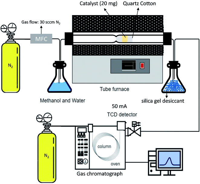
The as-combusted Zn-based catalysts were placed in a tubular reactor. The carrier gas used in the process was N2 with a flow rate of 30 sccm and a quartz tube inner diameter of 1.2 cm. A flowchart of the SRM process is presented in Fig. 1. The gas product converted in the process was analyzed and measured several times at each reaction temperature with a GC-1000 gas chromatograph equipped with a thermal conductivity detector and the resulting values were averaged. Before the catalysts were testing, all of the specific samples with and without activation by flow reactor received pre-oxidation treatment by annealing in a mixture of gas of 10% H2 and 90% N2 at 650 °C for 1 hour. For every experiment, 0.02 g of catalyst was put into a quartz tube. A gas chromatograph (GC 1000 Chromatography with TCD) with one column (60/80 Carboxen® 1000) for H2 (7 ft 1/16 in, stainless steel) was used to measure the hydrogen production. In the gas chromatograph, a thermal conductivity detector with a current of 50 mA was fitted. The H2 production performances of the ZnO–ZnCr2O4 and ZnCr2O4 catalysts were investigated based on the H2 production rate from the gas chromatograph.58,59
 | (7) |
 | (8) |
3. Results and discussion
3.1 Characteristics of ZnO–ZnCr2O4 composite catalyst and ZnCr2O4 catalyst prepared by GNP
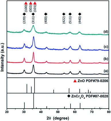
XRD studies of the as-combusted catalysts were performed with the database software Powder-XRD. Fig. 2(a–d) reveal the XRD patterns of as-combusted ZnCr2O4 (GNP: 1.5, 1.7) and ZnO–ZnCr2O4 (GNP: 1.5, 1.7). The XRD curves in Fig. 2(a) and (b) reveal the diffraction patterns of ZnCr2O4 prepared with G/N ratios of 1.5 and 1.7. The diffraction spectra of the cubic phase spinel ZnCr2O4 (PDF# 87-0028) showed diffractions at 30.3°, 35.7°, 43.4°, 53.8°, 57.4° and 63.1°, which corresponded to the (220), (311), (400), (422), (511) and (400) planes. On the other hand, the diffraction pattern of the ZnO phase in Fig. 2(c) was based on the increasing metal source ratio of zinc nitrate to chromium nitrate. Furthermore, Fig. 2(d) shows that the intensity of the ZnO diffraction peak decreased due to the decrease in the G/N ratio because the conditions were insufficient for the ZnO phase to crystallize. Meanwhile, the ZnO–ZnCr2O4 synthesized with a lower G/N ratio, the reaction temperature would decrease, and the diffraction peaks became broader which revealed the crystallite of the ZnO–ZnCr2O4 was smaller. The diffraction patterns of hexagonal phase ZnO (PDF# 79-0206) are shown in Fig. 2(c). The peaks at 31.7°, 34.4°, and 36.2° corresponded to the (100), (002) and (101) planes. Based on the XRD patterns of as-combusted ZnCr2O4 (GNP: 1.5, 1.7) and ZnO–ZnCr2O4 (GNP: 1.5, 1.7), immiscibility of ZnO and ZnCr2O4 was judged by the non-shift XRD peak from the ZnO–ZnCr2O4, and no other secondary phases such as Cr2O3 and ZnCrO4 were observed in the pattern.Moreover, the activated catalysts were respectively investigated for their characterization. Fig. 3 showed the XRD patterns of catalysts after activation. Fig. 3(a) ZnCr2O4 catalyst prepared by the GNP method with G/N ratios 1.7 revealed the phase remained ZnCr2O4 spinel phase and Fig. 3(b) ZnO–ZnCr2O4 catalyst prepared by the GNP method with G/N ratios 1.7 revealed the ZnCr2O4 spinel phase and slightly ZnO hexagonal phase, respectively.
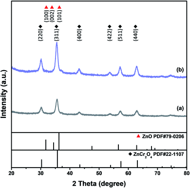 | ||
| Fig. 3 XRD patterns of activated (a) ZnCr2O4 and (b) ZnO–ZnCr2O4 catalyst prepared by the GNP method with G/N ratios 1.7. | ||
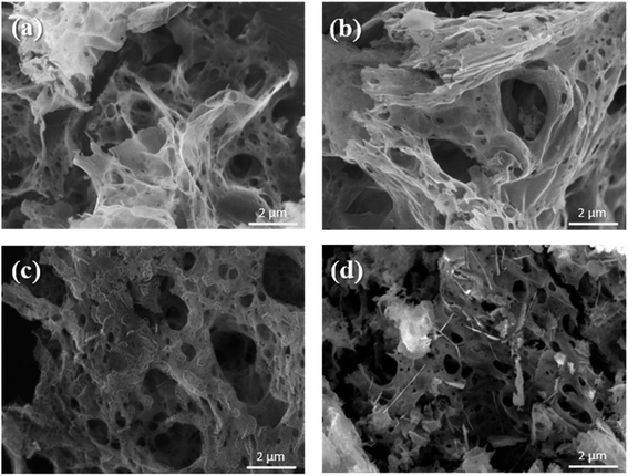
The microscopic surface morphologies and the structures of the as-combusted catalysts were analyzed by FESEM. Fig. 4 presents FESEM images of (a) ZnCr2O4 prepared by the GNP method with a G/N ratio of 1.7, (b) ZnCr2O4 prepared by the GNP method with a G/N ratio of 1.5, (c) ZnO–ZnCr2O4 prepared by the GNP method with a G/N ratio of 1.7, and (d) ZnO–ZnCr2O4 prepared by the GNP method with a G/N ratio of 1.5 before the SRM treatment. The as-combusted ZnCr2O4 presented a coral-like porous structure due to the gas that was released during the reaction. However, the hexagonal flakes attached to the porous structure in Fig. 4(c) and (d) were ZnO, corresponding to the XRD result in Fig. 2. Based on the XRD and SEM analysis the of as-combusted catalysts, the ZnO was in the amorphous phase in the ZnO–ZnCr2O4 during the GNP when the G/N ratio was 1.5. Moreover, the as-combusted catalyst after activation still retains the porous structure which was shown in Fig. 5. However, compared to Fig. 4 and 5, the pore on the catalyst and the ZnO attached on the catalyst surface was shown to be smaller. Thus, it is exhibited that agglomeration occurs after activation.
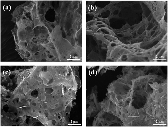 | ||
| Fig. 4 SEM images of ZnCr2O4 catalysts prepared by the GNP method with G/N ratios of (a) 1.7 and (b) 1.5, and ZnO–ZnCr2O4 catalysts prepared by the GNP method with G/N ratios of (c) 1.7 and (d) 1.5. | ||
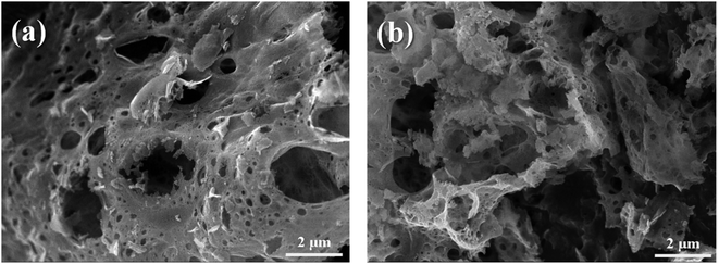 | ||
| Fig. 5 SEM images of activated (a) ZnCr2O4 and (b) ZnO–ZnCr2O4 catalyst prepared by the GNP method with G/N ratios 1.7. | ||
The specific surface areas of the as-combusted ZnO–ZnCr2O4 and ZnCr2O4 catalysts prepared by GNP (with G/N ratios of 1.5 and 1.7) are listed in Table 1. Before BET analysis, the remaining absorbed water was removed from the catalysts by high purity N2 flow at 200 °C for 24 hours. N2 adsorption isotherms were investigated at various relative pressures while the catalyst adsorbed N2. A high specific surface area would facilitate the catalytic reaction.60 Based on the BET results, the specific surface areas of the as-combusted ZnO–ZnCr2O4 and ZnCr2O4 catalysts ranged from 29 m2 g−1 to 46 m2 g−1, and the results of BET revealed a large SBET. Furthermore, the surface areas of the ZnO–ZnCr2O4 and ZnCr2O4 catalysts decreased as the G/N ratio increased. Furthermore, the surface area of the activated ZnCr2O4 and ZnO–ZnCr2O4 (G/N = 1.7) catalyst was 27 m2 g−1 and 48 m2 g−1, respectively. Compared to the ZnO–ZnCr2O4 catalyst with G/N ratios of 1.7 before and after the activation, the surface area was increased by more than about 30% which could correspond to the catalyst test result shown in Table 3 and Fig. 9.
| Composition | Specific surface area (m2 g−1) | |
|---|---|---|
| Original catalyst | Activated catalyst | |
| ZnCr2O4 G/N-1.7 | 29 | 27 |
| ZnCr2O4 G/N-1.5 | 46 | — |
| ZnO–ZnCr2O4 G/N-1.7 | 35 | 48 |
| ZnO–ZnCr2O4 G/N-1.5 | 45 | — |
3.2 Characteristics of ZnO–ZnCr2O4 composite catalyst and ZnCr2O4 catalyst after SRM treatment
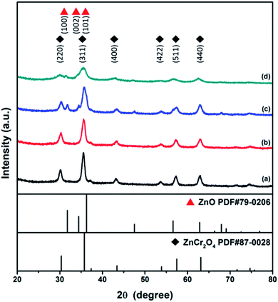
Fig. 6 presents the X-ray diffraction patterns of ZnCr2O4 and ZnO–ZnCr2O4 prepared by the GNP method with G/N ratios of 1.5 and 1.7 after steam reforming treatment. As shown in the XRD patterns, the ZnCr2O4 and ZnO–ZnCr2O4 catalysts retained the cubic phase spinel structure of ZnCr2O4 (PDF# 87-0028) after the catalyst test, as revealed by Fig. 6(a–d). Moreover, after the SRM treatment, the crystallinity of the ZnO phase in the ZnO–ZnCr2O4 composite catalyst was significantly improved. This indicated that the ZnO particles attached to the surface of the catalyst experienced grain growth during the SRM process, as shown in Fig. 6(c) and (d).SEM images of the ZnCr2O4 and ZnO–ZnCr2O4 (G/N ratio 1.5 and 1.7) catalysts after steam reforming treatment are presented in Fig. 7. As can be seen in the figure, they still retained the porous structure produced in the GNP process. Because of the gas product generated during the reaction of SRM, the porous structure of ZnCr2O4 and ZnO–ZnCr2O4 catalyst was retained, as shown in Fig. 7(a–d). It can be seen from the SEM images in Fig. 7(c) and (d) that the addition of ZnO to the ZnCr2O4 catalyst increased the number of active sites and contributed to hydrogen production in the SRM process.
For the catalyst test in this study, the ZnCr2O4 and ZnO–ZnCr2O4 catalysts prepared under different conditions were evaluated according to the hydrogen production rate (ml STP min−1 g-cat−1), and the efficiencies of the ZnCr2O4 and ZnO–ZnCr2O4 catalysts with and without activation were also compared. The H2 production rate was estimated with a gas chromatograph equipped with TCD. The catalyst was placed in the reaction bed for the SRM process at temperatures of 350 °C to 500 °C, and then the reacted gas was assisted by the N2 at a flow rate of 30 sccm. The catalyst was thermally treated at the reaction temperature prior to the reaction without contact with methanol vapor to maximize the hydrogen conversion capacity and the life of the catalyst.47
The hydrogen production rates of the ZnCr2O4 and ZnO–ZnCr2O4 catalysts prepared with different G/N ratios at reaction temperatures of 350 °C to 500 °C are listed in Table 2. The H2 production rates of the ZnCr2O4 and ZnO–ZnCr2O4 catalysts are illustrated in Fig. 8. It can be seen that, when the reaction temperature rose, the hydrogen production performance of the catalyst increased. The ZnO–ZnCr2O4 G/N-1.7 composite catalyst had the best hydrogen production efficiency when the gas product was carried by N2, the N2 flow rate was 30 sccm, and the temperature was 450 °C. The hydrogen production rate of the ZnO–ZnCr2O4 G/N-1.7 composite catalyst was estimated at 4814.25 ml STP min−1 g-cat−1. According to this result, the catalytic performance improved when the optimum catalyst reaction temperature decreased after the addition of ZnO. Zhang et al. reported that the incorporation of ZnO could affect the hydrogen production rate and that a suitable amount of ZnO content in the catalyst modified the active site on the surface and limited the agglomeration of the particles.61 Moreover, H2 production enhancement by the ZnO incorporation into ZnCr2O4 which was binary crystal structure ZnO–ZnCr2O4 formed with a close connection of hexagonal ZnO and ZnCr2O4 phases and it was helpful to improve the interaction between ZnO and ZnCr2O4. Xiaofeng et al. reported the morphology and facet of ZnO played an important role in affecting its catalytic activity. Several studies have reported that the terminal polar (0001) facets were more active surfaces for catalysis than the nonpolar surfaces perpendicular to them.62
| Rate of H2 production (ml STP min−1 g-cat−1) | ||||
|---|---|---|---|---|
| Composition | 350 °C | 400 °C | 450 °C | 500 °C |
| ZnCr2O4 G/N-1.7 | 1714 | 2700 | 3549 | 2410 |
| ZnCr2O4 G/N-1.5 | 2453 | 2753 | 4122 | 4402 |
| ZnO–ZnCr2O4 G/N-1.7 | 1286 | 3046 | 4814 | 3954 |
| ZnO–ZnCr2O4 G/N-1.5 | 1860 | 2573 | 4074 | 2663 |
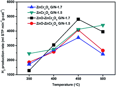 | ||
| Fig. 8 The H2 production rates of ZnO–ZnCr2O4 and ZnCr2O4 catalysts prepared by the GNP method at different temperatures with a N2 flow rate of 30 sccm. | ||
A high hydrogen production rate is essential for the realization of fuel cells for automotive and mobile applications. However, hydrogen production reactors are generally dangerous due to flammability and explosion hazards. However, the ZnO–ZnCr2O4 composite catalyst can be used directly without high-temperature activation, and it is extremely stable. Therefore, the catalyst in this study would be useful in vehicles with fuel cells because of its simple hydrogen production by SRM and its high efficiency.
Furthermore, the hydrogen production rates of the activated catalysts were also respectively investigated. The ZnO–ZnCr2O4 and ZnCr2O4 catalysts were activated in a mixture of 10% H2 and 90% N2 gas at 650 °C for 1 hour before the SRM process. The results of the catalyst tests are listed in Table 3 and illustrated in Fig. 9. According to the results, the optimal reaction temperature of ZnO–ZnCr2O4 composite increased to 500 °C. However, the optimal reaction temperature was increased because of the thermal treatment during the activation. Liyan et al. reported that ZnO–ZnCr2O4 composite treated with various thermal treatments revealed a reduction shift to the higher temperature in thermal treatment, indicating the synergetic effect shown by ZnO and ZnCr2O4.48 The activated ZnO–ZnCr2O4 G/N-1.7 had the best hydrogen production rate, which reached 6299 ml STP min−1 g-cat−1. The activated ZnO–ZnCr2O4 composite catalyst also had higher activity and hydrogen production than those of the inactivated ZnO–ZnCr2O4 composite catalyst.
| Rate of H2 production (ml STP min−1 g-cat−1) | ||
|---|---|---|
| Reactor temperature | ZnO–ZnCr2O4 G/N-1.7 (activated) | ZnCr2O4 G/N-1.7(activated) |
| 350 °C | 1681 | 1035 |
| 400 °C | 2467 | 2272 |
| 450 °C | 4185 | 3896 |
| 500 °C | 6299 | 5865 |
| 550 °C | 4503 | 3571 |
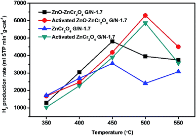 | ||
| Fig. 9 H2 production rates of activated ZnO–ZnCr2O4 and ZnCr2O4 catalysts (G/N-1.7) at different temperatures with a N2 flow rate of 30 sccm. | ||
Fig. 10 compares the hydrogen production rates of ZnO–ZnCr2O4 and ZnCr2O4 powders prepared by GNP (with and without activation); a commercial catalyst;24 CuCrO2 bulk powder,26 CuCrO2, CuFeO2, and CuFeO2–CeO2 nanopowders prepared by GNP.8,14 The results show that the catalytic performance in hydrogen production reported in this study was higher than those of the aforementioned catalysts. Furthermore, the stability and the cycle-life were studied. Furthermore, the stability and the cycle-life were studied. In addition, to investigate the reusability of the ZnO–ZnCr2O4 composite catalyst, Fig. 11 was shown ZnO–ZnCr2O4 composite catalyst activity of changes with repeated cycle test during the SRM process which reacted at 450 °C with an N2 flow rate of 30 sccm. ZnO–ZnCr2O4 composite after 3 times SRM treatment, the H2 production rates of the ZnO–ZnCr2O4 composite G/N-1.7 decreased by about 90%.
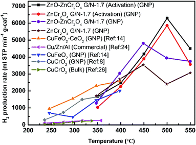 | ||
| Fig. 10 The H2 production rates in SRM of the ZnO–ZnCr2O4 and ZnCr2O4 powders prepared by GNP with and without the activation inflow rate of 30 sccm, and the H2 production rates of a commercial catalyst,24 CuCrO2 bulk powder,26 and the CuCrO2, CuFeO2, and CuFeO2–CeO2 nanopowders prepared by GNP.8,14 | ||
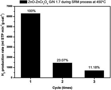 | ||
| Fig. 11 The cycle test study of ZnO–ZnCr2O4 catalyst (G/N-1.7) during SRM at 450 °C with a N2 flow rate of 30 sccm. | ||
Based on the characteristics of the ZnO–ZnCr2O4 composite catalyst and ZnCr2O4 catalyst after SRM treatment, the ZnO–ZnCr2O4 and ZnCr2O4 catalysts prepared by the GNP method showed a reasonable degree of stability and exhibited better catalytic efficiency than those of the previous copper-based catalyst. The appropriate incorporation of ZnO in the ZnO–ZnCr2O4 catalyst increased the active sites and contributed to the hydrogen production function.
4. Conclusions
A zinc-based catalyst, namely, ZnO–ZnCr2O4 porous composite was prepared by GNP with G/N ratios of 1.7 and 1.5. The catalysts prepared in this study were applied to hydrogen production by SRM. The ZnO–ZnCr2O4 porous composite catalysts, before activation pretreatment, exhibited superior catalytic performance in the SRM process as compared with the previous copper-based catalyst and a commercial catalyst. Without activation pretreatment, the ZnO–ZnCr2O4 porous composite catalyst made with a G/N ratio of 1.7 revealed the best hydrogen production rate, 4814 ml STP min−1 g-cat−1, at a reaction temperature of 450 °C and N2 flow rate of 30 sccm. After activation, the ZnO–ZnCr2O4 porous composite catalyst exhibited hydrogen production of 6299 ml STP min−1 g-cat−1 at 500 °C and a N2 flow rate of 30 sccm. Furthermore, to investigate the characteristics of the catalyst prepared by GNP and the catalyst after the SRM process, the ZnO–ZnCr2O4 porous composite catalysts were analyzed by XRD, FE-SEM, and BET. The catalytic performance was determined by GC-TCD. Due to the GNP process, the catalyst had a porous structure, which effectively increased the specific surface area and thus the catalytic activity. The ZnO–ZnCr2O4 porous composite catalyst features a simple process with good performance for hydrogen production from SRM. The advantages of the ZnO–ZnCr2O4 composite catalyst make it a potential material for fuel cells in automobiles.Conflicts of interest
The authors declare that they have no known competing financial interests or personal relationships that could have appeared to influence the work reported in this paper.Acknowledgements
This work was supported by the Ministry of Science and Technology of Taiwan (MOST 108-2221-E-027-056, MOST 109-2221-E-027-068, MOST 109-2221-E-027-059, and MOST 109-2113-M-027-001-MY3). This work was supported by the National Science and Technology Council of Taiwan (NSTC 111-2221-E-027-104). This work was supported by University System of Taipei Joint Research Program (USTP-NTUT-TMU-111-01). The authors appreciate the Precision Research and Analysis Centre of National Taipei University of Technology (NTUT) for providing the measurement facilities.References
- N. Armaroli and V. Balzani, The future of energy supply: Challenges and opportunities, Angew. Chem., Int. Ed., 2007, 46, 52–66 CrossRef CAS PubMed.
- C. Pojanavaraphan, A. Luengnaruemitchai and E. Gulari, Hydrogen production by oxidative steam reforming of methanol over Au/CeO2 catalysts, Chem. Eng. J., 2012, 192, 105–113 CrossRef CAS.
- V. Shanmugam, S. Neuberg, R. Zapf, H. Pennemann and G. Kolb, Hydrogen production over highly active Pt based catalyst coatings by steam reforming of methanol: Effect of support and co-support, Int. J. Hydrogen Energy, 2019, 45, 1658–1670 CrossRef.
- N. Edwards, S. R. Ellis, J. C. Frost, S. E. Golunski, A. N. J. V. Keulen, N. G. Lindewald and J. G. Reinkingh, On-board hydrogen generation for transport applications: The HotSpotTM methanol processor, J. Power Sources, 1998, 71, 123–128 CrossRef CAS.
- C. Song, Fuel processing for low-temperature and high-temperature fuel cells: Challenges, and opportunities for sustainable development in the 21st century, Catal. Today, 2002, 77, 17–49 CrossRef CAS.
- M. A. K. Lodhi and R. W. Mires, How safe is the storage of liquid hydrogen ?, Int. J. Hydrogen Energy, 1989, 14, 35–43 CrossRef CAS.
- T. W. Chiu and Y. S. Lu, Preparation of CuCr1-xFexO2 delafossite solid solution powder via a self-combustion glycine nitrate process, Ferroelectrics, 2016, 491, 149–154 CrossRef CAS.
- T. W. Chiu, R. T. Hong, B. S. Yu, Y. H. Huang, S. Kameoka and A. P. Tsai, Improving steam-reforming performance by nanopowdering CuCrO2, Int. J. Hydrogen Energy, 2014, 39, 14222–14226 CrossRef CAS.
- S. Schuyten and E. E. Wolf, Selective combinatorial studies on Ce and Zr promoted Cu/Zn/Pd catalysts for hydrogen production via methanol oxidative reforming, Catal. Lett., 2006, 106, 7–14 CrossRef CAS.
- S. F. Wang, C. M. Lu, Y. C. Wu, Y. C. Yang and T. W. Chiu, La2O3-Al2O3-B2O3-SiO2 glasses for solid oxide fuel cell applications, Int. J. Hydrogen Energy, 2011, 36, 3666–3672 CrossRef CAS.
- H. Ji, J. Lee, E. Choi and I. Seo, Hydrogen production from steam reforming using an indirect heating method, Int. J. Hydrogen Energy, 2018, 43, 3655–3663 CrossRef CAS.
- M. Turco, G. Bagnasco, U. Costantino, F. Marmottini, T. Montanari, G. Ramis and G. Busca, Production of hydrogen from oxidative steam reforming of methanol: I. Preparation and characterization of Cu/ZnO/Al2O3 catalysts from a hydrotalcite-like LDH precursor, J. Catal., 2004, 228, 43–45 CAS.
- D. R. Palo, R. A. Dagle and J. D. Holladay, Methanol steam reforming for hydrogen production, Chem. Rev., 2007, 107, 3992–4021 CrossRef CAS PubMed.
- C. L. Yu, S. Sakthinathan, B. Y. Hwang, S. Y. Lin, T. W. Chiu, B. S. Yu, Y. J. Fan and C. Chuang, CuFeO2–CeO2 nanopowder catalyst prepared by self-combustion glycine nitrate process and applied for hydrogen production from methanol steam reforming, Int. J. Hydrogen Energy, 2020, 45, 15752–15762 CrossRef CAS.
- J. D. Holladay, Y. Wang and E. Jones, Review of developments in portable hydrogen production using microreactor technology, Chem. Rev., 2004, 104, 4767–4789 CrossRef CAS PubMed.
- S. Velu, K. Suzuki, M. P. Kapoor, F. Ohashi and T. Osaki, Selective production of hydrogen for fuel cells via oxidative steam reforming of methanol over CuZnAl(Zr)-oxide catalysts, Appl. Catal., A, 2001, 213, 47–63 CrossRef CAS.
- T. Shishido, Y. Yamamoto, H. Morioka and K. Takehira, Production of hydrogen from methanol over Cu/ZnO and Cu/ZnO/Al2O3 catalysts prepared by homogeneous precipitation: Steam reforming and oxidative steam reforming, J. Mol. Catal. A: Chem., 2007, 268, 185–194 CrossRef CAS.
- C. M. Kalamaras and A. M. Efstathiou, Hydrogen Production Technologies: Current State and Future Developments, Conf Pap Energy, 2013, pp. 1–9 Search PubMed.
- H. S. Pajaie, Hydrogen Production from Methanol Steam Reforming over Cu/ZnO/Al2O3/CeO2/ZrO2 Nanocatalyst in an Adiabatic Fixed-Bed Reactor, Iran. J. Energy Environ., 2012, 3, 307–313 Search PubMed.
- J. Papavasiliou, G. Avgouropoulos and T. Ioannides, Production of hydrogen via combined steam reforming of methanol over CuO-CeO2 catalysts, Catal. Commun., 2004, 5, 231–235 CrossRef CAS.
- J. C. Brown and E. Gulari, Hydrogen production from methanol decomposition over Pt/Al2O3 and ceria promoted Pt//Al2O3 catalysts, Catal. Commun., 2004, 5, 431–436 CrossRef CAS.
- M. G. Poirier and C. Sapundzhiev, Catalytic decomposition of natural gas to hydrogen for fuel cell applications, Int. J. Hydrogen Energy, 1997, 22, 429–433 CrossRef CAS.
- J. Agrell, K. Hasselbo, K. Jansson, S. G. Jaras and M. Boutonnet, Production of hydrogen by partial oxidation of methanol over Cu/ZnO catalysts prepared by microemulsion technique, Appl. Catal., A, 2001, 211, 239–250 CrossRef CAS.
- S. Kameoka, T. Tanabe and A. P. Tsai, Self-assembled porous nano-composite with high catalytic performance by reduction of tetragonal spinel CuFe2O4, Appl. Catal., A, 2010, 375, 163–171 CrossRef CAS.
- R. P. Hernandez, G. M. Galicia, D. M. Anaya, J. Palacios, C. A. Chavez and J. A. Alatorre, Synthesis and characterization of bimetallic Cu-Ni/ZrO2 nanocatalysts: H2 production by oxidative steam reforming of methanol, Int. J. Hydrogen Energy, 2008, 33, 4569–4576 CrossRef.
- S. Kameoka, M. Okada and A. P. Tsai, Preparation of a novel copper catalyst in terms of the immiscible interaction between copper and chromium, Catal. Lett., 2008, 120, 252–256 CrossRef CAS.
- T. L. Reitz, S. Ahmed, M. Krumpelt, R. Kumar and H. H. Kung, Characterization of CuO/ZnO under oxidizing conditions for the oxidative methanol reforming reaction, J. Mol. Catal. A: Chem., 2000, 162, 275–285 CrossRef CAS.
- M. V. Twigg and M. S. Spencer, Deactivation of supported copper metal catalysts for hydrogenation reactions, Appl. Catal., A, 2001, 212, 161–174 CrossRef CAS.
- N. Liu, Z. Yuan, S. Wang, C. Zhang, S. Wang and D. Li, Characterization and performance of a ZnO-ZnCr2O4/CeO2-ZrO2 monolithic catalyst for methanol auto-thermal reforming process, Int. J. Hydrogen Energy, 2008, 33, 1643–1651 CrossRef CAS.
- S. Chandrasekaran, D. Ma, Y. Ge, L. Deng, C. Bowen, J. Roscow, Y. Zhang, Z. Lin, R. D. K. Misra, J. Li, P. Zhang and H. Zhang, Electronic structure engineering on two-dimensional (2D) electrocatalytic materials for oxygen reduction, oxygen evolution, and hydrogen evolution reactions, Nano Energy, 2020, 77, 105080 CrossRef CAS.
- S. Chandrasekaran, L. Yao, L. Deng, C. Bowen, Y. Zhang, S. Chen, Z. Lin, F. Peng and P. Zhang, Recent advances in metal sulfides: from controlled fabrication to electrocatalytic, photocatalytic and photoelectrochemical water splitting and beyond, Chem. Soc. Rev., 2019, 48, 4178–4280 RSC.
- R. Kalia, Pushpendra, R. K. Kunchala, S. N. Achary and B. S. Naidu, New insights on photocatalytic hydrogen evolution of ZnFe2−xGaxO4 (0 ≤ x ≤ 2) solid solutions: Role of oxygen vacancy and ZnO segregated phase, J. Alloys Compd., 2021, 875, 159905 CrossRef CAS.
- Y. F. Li, X. F. Dong and W. M. Lin, Effects of ZrO2-promoter on catalytic performance of CuZnAlO catalysts for production of hydrogen by steam reforming of methanol, Int. J. Hydrogen Energy, 2004, 29, 1617–1621 CrossRef CAS.
- P. H. Matter, D. J. Braden and U. S. Ozkan, Steam reforming of methanol to H2 over nonreduced Zr-containing CuO/ZnO catalysts, J. Catal., 2004, 223, 340–351 CrossRef CAS.
- B. Lindström, L. J. Pettersson and G. Menon, Activity and characterization of Cu/Zn, Cu/Cr and Cu/Zr on γ-alumina for methanol reforming for fuel cell vehicles, Appl. Catal., A, 2002, 234, 111–125 CrossRef.
- W. Tong, A. West, K. Cheung, K. M. Yu and S. C. E. Tsang, Dramatic effects of gallium promotion on methanol steam reforming Cu-ZnO catalyst for hydrogen production: Formation of 5Å copper clusters from Cu-ZnGaOx, ACS Catal., 2013, 3, 1231–1244 CrossRef CAS.
- S. Chandrasekaran, C. Zhang, Y. Shu, H. Wang, S. Chen, T. Nesakumar Jebakumar Immanuel Edison, Y. Liu, N. Karthik, R. D. K. Misra, L. Deng, P. Yin, Y. Ge, O. A. A. Hartomy, A. A. Ghamdi, S. Wageh, P. Zhang, C. Bowen and Z. Han, Advanced opportunities and insights on the influence of nitrogen incorporation on the physico-/electro-chemical properties of robust electrocatalysts for electrocatalytic energy conversion, Coord. Chem. Rev., 2021, 449, 214209 CrossRef CAS.
- S. Chandrasekaran, M. Khandelwal, F. Dayong, L. Sui, J. S. Chung, R. D. K. Misra, P. Yin, E. J. Kim, W. Kim, A. Vanchiappan, Y. Liu, S. H. Hur, H. Zhang and C. Bowen, Developments and perspectives on robust nano-and microstructured binder-free electrodes for bifunctional water electrolysis and beyond, Adv. Energy Mater., 2022, 12, 2200409 CrossRef CAS.
- L. A. Ying, J. Liu, L. Mo, H. Lou and X. Zheng, Hydrogen production by oxidative steam reforming of methanol over Ce1-xZnxOy catalysts prepared by combustion method, Int. J. Hydrogen Energy, 2012, 37, 1002–1006 CrossRef CAS.
- S. Y. Lin, T. W. Chiu and C. Dong, Preparation and characterization of CuCrO2-CeO2 composite nanopowder by a self-combustion glycine nitrate process, Ceram. Int., 2017, 43, S639–S642 CrossRef CAS.
- S. Dey, B. S. Naidu and C. N. R. Rao, Ln0.5A0.5MnO3 (Ln = Lanthanide, A = Ca, Sr) Perovskites exhibiting remarkable performance in the thermochemical generation of CO and H2 from CO2 and H2O, Chem. – Eur. J., 2015, 21, 7077–7081 CrossRef CAS PubMed.
- S. Dey, B. S. Naidu and C. N. R. Rao, Beneficial effects of substituting trivalent ions in the B-site of La0.5Sr0.5Mn1−xAxO3 (A = Al, Ga, Sc) on the thermochemical generation of CO and H2 from CO2 and H2O, Dalton Trans., 2016, 45, 2430–2435 RSC.
- S. Dey, B. S. Naidu, A. Govindaraj and C. N. R. Rao, Noteworthy performance of La1−xCaxMnO3 perovskites in generating H2 and CO by the thermochemical splitting of H2O and CO2, Phys. Chem. Chem. Phys., 2015, 17, 122–125 RSC.
- A. G. Merzhanov, Combustion and explosion processes in physical chemistry and technology of inorganic materials, Russ. Chem. Rev., 2003, 72, 323–345 CrossRef.
- L. A. Chick, L. R. Pederson, G. D. Maupin, J. L. Bates, L. E. Thomas and G. J. Exarhos, Glycine-nitrate combustion synthesis of oxide ceramic powders, Mater. Lett., 1990, 10, 6–12 CrossRef CAS.
- T. W. Chiu and P. S. Huang, Preparation of delafossite CuFeO2 coral-like powder using a self-combustion glycine nitrate process, Ceram. Int., 2013, 39, S575–S578 CrossRef CAS.
- B. Y. Hwang, S. Sakthinathan and T. W. Chiu, Production of hydrogen from steam reforming of methanol carried out by self-combusted CuCr1-xFexO2 (x = 0−1) nanopowders catalyst, Int. J. Hydrogen Energy, 2019, 44, 2848–2856 CrossRef CAS.
- L. Wang, X. Gao, Y. Bai, M. Tan, K. Suna, T. Zhang, Y. Wu, J. Pan, H. Xie and Y. Tana, The synergistic effect between ZnO and ZnCr2O4 on the catalytic performance for isobutanol synthesis from syngas, Fuel, 2019, 253, 1570–1577 CrossRef CAS.
- A. T. Baricevic, B. Grbic, D. Jovanovic, S. Angelov, D. Mehandziev, C. Marinova and P. K. Stefanov, Activity and sulphur tolerance of monophase spinels in carbon monoxide and CxHy oxidation, Appl. Catal., 1989, 47, 145–153 CrossRef.
- E. Tronconi, L. Lietti, P. Forzatti and I. Pasquon, Higher Alcohol Synthesis over Alkali Metal-Promoted High-Temperature Methanol Catalysts, Appl. Catal., 1989, 47, 317–333 CrossRef CAS.
- A. Abbasi, M. Hamadanian, M. S. Niasari and S. M. Derazkola, Facile size-controlled preparation of highly photocatalytically active ZnCr2O4 and ZnCr2O4/Ag nanostructures for removal of organic contaminants, J. Colloid Interface Sci., 2017, 500, 276–284 CrossRef CAS PubMed.
- N. Liu, Z. Yuan, S. Wang, C. Zhang, S. Wang and D. Li, Characterization and performance of a ZnO- ZnCr2O4/CeO2-ZrO2 monolithic catalyst for methanol auto-thermal reforming process, Int. J. Hydrogen Energy, 2008, 33, 1643–1651 CrossRef CAS.
- G. Drazic and M. Trontelj, Preparation and properties of ceramic sensor elements based on MgCr2O4, Sens. Actuators, 1989, 18, 407–414 CrossRef CAS.
- S. A. Hosseini and M. C. A. Galvan, Study of physical-chemical properties and catalytic activities of ZnCr2O4 spinel nano oxides obtained from different methods-Modeling the synthesis process by response surface methodology and optimization by genetic algorithm, J. Taiwan Inst. Chem. Eng., 2016, 61, 261–269 CrossRef CAS.
- J. Nakamura, T. Fujitani, S. Kuld, S. Helveg, I. Chorkendorff and J. Sehested, Active sites for CO2 hydrogenation to methanol on Cu/ZnO catalysts, Science, 2017, 357, 1296–1299 CrossRef PubMed.
- E. A. C. Miranda, J. F. M. Carvaja and O. J. R. Baena, Effect of the fuels glycine, urea and citric acid on synthesis of the ceramic pigment ZnCr2O4 by solution combustion, Mater. Res., 2015, 18, 1038–1043 CrossRef CAS.
- T. W. Chiu, B. S. Yu, Y. R. Wang, K. T. Chen and Y. T. Lin, Synthesis of nanosized CuCrO2 porous powders via a self-combustion glycine nitrate process, J. Alloys Compd., 2011, 509, 2933–2935 CrossRef CAS.
- M. Taghizadeh, H. Akhoundzadeh, A. Rezayan and M. Sadeghian, Excellent catalytic performance of 3D-mesoporous KIT-6 supported Cu and Ce nanoparticles in methanol steam reforming, Int. J. Hydrogen Energy, 2018, 43, 10926–10937 CrossRef CAS.
- A. Iulianelli, P. Ribeirinha, A. Mendes and A. Basile, Methanol steam reforming for hydrogen generation via conventional and membrane reactors: A review, Renewable Sustainable Energy Rev., 2014, 29, 355–368 CrossRef CAS.
- T. W. Chiu and Y. W. Feng, Preparation of CuCrO2 powders with high surface areas, Key Eng. Mater., 2014, 617, 187–190 CAS.
- G. Zhang, J. Zhao, T. Yang, Q. Zhang and L. Zhang, In-situ self-assembled Cu2O/ZnO core-shell catalysts synergistically enhance the durability of methanol steam reforming, Appl. Catal., A, 2021, 616, 118072 CrossRef CAS.
- X. Gao, T. Zhang, Y. Wu, G. Yang, M. Tan, X. Li, H. Xie, J. Pan and Y. Tan, Isobutanol synthesis from syngas on Zn-Cr based catalysts: New insights into the effect of morphology and facet of ZnO nanocrystal, Fuel, 2018, 217, 21–30 CrossRef CAS.
| This journal is © The Royal Society of Chemistry 2022 |

