DOI:
10.1039/D2RA03601K
(Review Article)
RSC Adv., 2022,
12, 23284-23310
Transition metal oxides as a cathode for indispensable Na-ion batteries
Received
10th June 2022
, Accepted 8th August 2022
First published on 17th August 2022
Abstract
The essential requirement to harness well-known renewable energy sources like wind energy, solar energy, etc. as a component of an overall plan to guarantee global power sustainability will require highly efficient, high power and energy density batteries to collect the derived electrical power and balance out variations in both supply and demand. Owing to the continuous exhaustion of fossil fuels, and ever increasing ecological problems associated with global warming, there is a critical requirement for searching for an alternative energy storage technology for a better and sustainable future. Electrochemical energy storage technology could be a solution for a sustainable source of clean energy. Sodium-ion battery (SIB) technology having a complementary energy storage mechanism to the lithium-ion battery (LIB) has been attracting significant attention from the scientific community due to its abundant resources, low cost, and high energy densities. Layered transition metal oxide (TMO) based materials for SIBs could be a potential candidate for SIBs among all other cathode materials. In this paper, we discussed the latest improvement in the various structures of the layered oxide materials for SIBs. Moreover, their synthesis, overall electrochemical performance, and several challenges associated with SIBs are comprehensively discussed with a stance on future possibilities. Many articles discussed the improvement of cathode materials for SIBs, and most of them have pondered the use of NaxMO2 (a class of TMOs) as a possible positive electrode material for SIBs. The different phases of layered TMOs (NaxMO2; TM = Co, Mn, Ti, Ni, Fe, Cr, Al, V, and a combination of multiple elements) show good cycling capacity, structural stability, and Na+ ion conductivity, which make them promising cathode material for SIBs. This review discusses and summarizes the electrochemical redox reaction, structural transformations, significant challenges, and future prospects to improve for NaxMO2. Moreover, this review highlights the recent advancement of several layered TMO cathode materials for SIBs. It is expected that this review will encourage further development of layered TMOs for SIBs.
 Archana Kanwade | Archana Kanwade received her Bachelor of Science Degree from Willingdon College under Shivaji University Kolhapur (2018) and her Master of Science Degree from Sir Parashurambhau College under Savitribai Phule Pune University (2020) with specialization in Physics. Archana Kanwade is admitted in August 2021 as a PhD scholar in the Department of Metallurgy Engineering and Materials Science in Indian Institute of Technology Indore and currently pursuing PhD in the Professor Dr P. M. Shirage's research lab. Her research work mainly focuses on “cathode materials for sodium-ion battery” and her research interests are in polyanionic based cathode materials for sodium-ion battery. |
 Sheetal Gupta | Sheetal Gupta obtained her master's degree in Physics in 2018 and is currently pursuing a Ph.D. in Material Science and Engineering at the Indian Institute of Technology Indore. Where she focuses on layered oxide cathode material for sodium-ion batteries, her research interest is sodium-ion batteries, lithium-ion batteries, and pseudocapacitor. She is enthusiastic about energy storage to provide sustainable and affordable energy storage devices for developing and developed parts of the world. |
 Akash Kankane | Akash Kankane has a bachelor's degree in Mechanical Engineering and is currently pursuing a Master of Technology in Material Science and Engineering at the Indian Institute of Technology Indore. His current research focuses on the high-performance electrode materials for sodium-ion batteries. His research interest is hard carbon, sodium-ion battery, and supercapattery. He is passionate about nanomaterials for batteries and high-performance batteries for renewable energy storage. |
 Manish Kumar Tiwari | Mr Manish Kumar Tiwari received his Master of Technology degree in Metallurgy Engineering and Materials Science with specialization in Materials Science and Engineering from Indian Institute of Technology Indore, India. He is currently working as a Ph.D. scholar in the Professor Dr P. M. Shirage's research lab at IITI. His research work mainly focuses on “next generation gas sensors” and his research interests include metal oxide based semiconducting materials, next generation perovskite materials and nano-materials for highly sensitive and selective gas and humidity sensors for environmental monitoring. |
 Abhishek Srivastava | Mr Abhishek Srivastava is currently working as a PhD student in the Department of Metallurgy Engineering and Materials Science at the Indian Institute of Technology, Indore, India. His current research work is totally inclined towards finding of lead free perovskite materials for solar cell application and some other hybrid module of solar cells such as dye sensitized solar cells. He also working for optoelectronic properties optimization of the solar radiation absorbing materials which are helpful in photovoltaics. During M.Sc. research, he worked on tin based alternate of lead halide perovskite solar cells. He has large interest to explore various stable stoichiometry which are reliable and promising candidate for highly efficient photovoltaic applications. |
 Jena Akash Kumar Satrughna | Mr Jena Akash Kumar Satrughna has received his Master of Science in Physics (M.Sc. Phys.) degree from Pondicherry University, Puducherry, India in 2019. He is currently working as a Ph.D., JRF scholar in the Department of Physics at the Indian Institute of Technology Indore (IIT Indore), Madhya Pradesh, India. His current research work is more focused towards the experimental and theoretical development and characterization of advanced cathode materials for sodium ion batteries. He also has sound knowledge and expertise on the anode materials for alkali-ion batteries and two-dimensional materials such as 2D-transition metal dichalcogenides (2D-TMDs) and 2D-Janus transition metal dichalcogenides (2D-JTMDs) as the efficient catalyst for hydrogen evolution reaction. |
 Subhash Chand Yadav | Mr Subhash Chandra Yadav completed his M.Sc. in Physics form Rajasthan University, Jaipur for the period of 2015–2017. He has been awarded with CSIR Fellowship with AIR-115 in Physics in the year 2015. He is currently working as the Ph.D. scholar in the Department of Metallurgy Engineering and Materials Science, Indian Institute of Technology Indore. His research interests are mainly based on the hybrid solar cell for energy harvesting applications. He has expertise in the dye sensitized, thin film and perovskite solar cells fabrication and characterization. |
 Parasharam M. Shirage | Professor Dr Parasharam M. Shirage received his Master and Doctoral Degree in Physics from the Shivaji University, Kolhapur (India), in 1999 and 2004 respectively. He has done his Post Doctorate from Korea Electrotechnology Research Institute, Changwon, South Korea from 2004–2006. He is currently working as a Professor in the Department of Metallurgy Engineering and Materials Science in Indian Institute of Technology Indore (India). He has served as Head of the Department and Dean Planning of the IITI. He was Visiting Fellow at Tata Institute of Fundamental Research (TIFR), Mumbai (2012–2013), Senior Scientist at National Institute of Advanced Industrial Science and Technology (AIST), Tsukuba, Japan (2008–2012). He is recipient of highly prestigious JSPS Postdoctoral Fellowship in 2006–2008, Ramanujan Fellowship from Government of India in 2013 and Medal from Materials Research Society of India (MRSI) in 2020. He is a fellow of Maharashtra Academy of Sciences. His research interests include areas such as novel superconductor search, electrochemistry, thin film growth, nano-materials for emerging third generation solar cells and energy storage applications (supercapacitors and batteries), sustainable sodium-ion batteries, gas sensing, etc. In these areas, he has more than 207 research publications in international peer reviewed journals and 5 patents to his credit with citation over 5184 with h-index 41, i10 index of 121 at the date of updating the profile. He is reviewer for AIP, APS, ACS, IOP, Elsevier, Springer, etc. journals. |
1. Introduction
The global energy expenditure has increased rapidly throughout the last two decades, so there is a need to develop energy storage technology with superior performance and sustainability.1,2 As energy appears in various forms like heat, radiation, electricity, chemistry, and gravity, energy storage methods that involve transforming energy from different forms that are challenging to collect are indispensable for the economic usage of energy.3–5
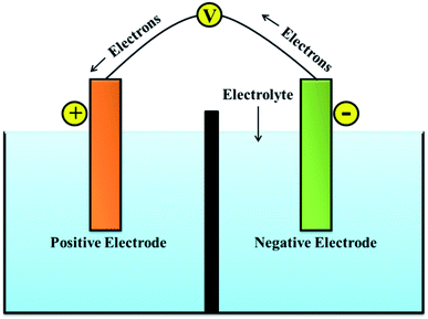
A battery can store electrical energy in the form of chemicals and redox reactions, and it provides direct current electricity.6 While discharging, the equations define a chemical reduction process by gaining electrons at the positive electrode, and an oxidation process by losing electrons at the negative electrode. The recharge of a secondary battery is a reversal of the processes that occur during discharge.7 The service of batteries lies in the wide variety of sizes in which they can be assembled or manufactured into packs. Their portability (for smaller sizes) and the capacity to immediately provide electrical power is the most convenient property.8–10 A single cell of the battery is composed of an electrolyte, a separator, a negative electrode, and a positive electrode as presented in Fig. 1.11
 |
| | Fig. 1 Schematic of battery system. | |
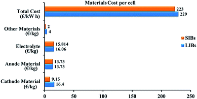
An electrolyte is an electronically insulating and ionically conducting source that permits the redox reaction on both electrodes. While using electrolytes in liquid form, a porous film needs to be placed as the separator separating the anode and cathode to ignore the electrical connection.12,13 The separator enables the liquid electrolyte to penetrate and separates the anode and cathode from contacting each other.14 A cell is the core component of a battery. For various compact electronic devices, a single cell can meet the power and energy demands. For large-scale utilization in electric vehicles, multiple cells are electrically integrated as modules and packed into a battery pack to satisfy the power and energy requirements.15 Lithium is widely used in the energy storage devices because it has a high energy density. Nevertheless, limited lithium resources are unable to fulfil the supply for large-scale utilization, particularly for the grid-scale storage of energy.16 Sodium is abundant in natural resources, so its price is low; sodium-ion batteries are becoming a possible replacement for lithium-ion batteries.17 An obvious replacement for lithium is sodium because of its analogous chemical properties.18 Investigations into SIBs started in the 1970s along with LIBs, but real research work only began after Sony was successful marketing LIBs in 1990.19 Despite the higher ionic radius that sodium (1.02 Å) has over lithium (0.76 Å), the cost per kW h of energy that sodium provide is less than the lithium can provide. The cost of fabrication of LIB and SIB is represented Fig. 2. A brief comparison between lithium and sodium can be seen in Table 1.20
 |
| | Fig. 2 Evaluation of the fabrication costs for LIB and SIB.21 | |
Table 1 Characteristics of lithium vs. sodium
| Category |
Lithium |
Sodium |
| Atomic weight |
6.9 g mol−1 |
23 g mol−1 |
| Cation radius |
0.76 Å |
1.02 Å |
| Cost |
High |
Low |
| Preferred coordination |
Tetrahedral and octahedral |
Prismatic and octahedral |
| Capacity (mA h g−1) |
3829 |
1165 |
| E0 (vs. Li/Li+) |
0 |
0.3 V |
It is worthy to note that SIBs had also been considered in the early days of lithium-ion battery research.22 The analysis, however, was largely interrupted, most likely due to slow progress and the successful chemistry of LIB.23 Today, the main inspiration for the research on SIBs is the abundance (less prone to resource issues) of sodium and the expectation is to manufacture cheap batteries compared to LIBs. Gross performance and the entire cost of SIBs are depends on one of the key components, cathode material. Still, it is difficult to stabilize the structure and enhance the electrochemical performance of the cathode material to satisfy the requirements of the practical application.24,25 Based on the chemical replacement of the prototypical cathode, LiCoO2 the structure of cathode materials in most of the best performing lithium-ion batteries is layered two-dimensional crystallographic.26
Fig. 3 represents the number of scientific publications on Na-ion battery, and layered oxide cathodes. The key challenges for commercialization of SIBs are the limited cycle life and low energy density of electrode materials.27 Cathode is mainly valuable and significantly controls the cycle life and energy density. It is challenging to simply replicate a cathode from its lithium equivalent to manufacture electrodes for SIBs due to the larger ionic radius of Na+ and marginally different chemistry between Li+ ions and Na+ ions.28 The cathode material for the most promising SIB has the same but rich, multilayered geometry. It has been well recognized that the electrochemical performance of an electrode material is strongly connected to its intrinsic crystal structure.29 Layered transition metal oxides are one of the best options available for the cathode of SIBs. Various properties like cyclic number and capacity of the SIBs depends on structure of layered oxide material. The stacking arrangements of layered TMOs was demonstrated by Delmas and Hagenmuller.30
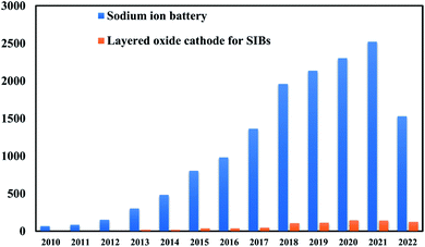 |
| | Fig. 3 Graphical representation of number of scientific publications on Na-ion battery and layered cathode materials every year from 2000 to 2021. (Data are encapsulated from Scopus). | |
Fig. 4 shows the comparison of charge/discharge plots of Li/LiCoO2 and Na/NaCoO2 cells. A larger ionic radius of the sodium ion is the result of an extra structural richness, which has an extended octahedral geometry determined in the cathode material of Li-ion. The coordination environment of the alkali metal is denoted by either O for octahedral or P for prismatic coordination, followed by a number denoting the layers of transition metal in the stacking repeat unit. The large MO6 sheets gives 2D transport channels for the insertion/extraction of Na+ ions in between them, offering high specific capacity to NaxMO2.32 After crystallization, its configuration is trigonal prismatic. This additional versatility of structural offers the possibility to modify for energy and power applications. It suggests the direction of research for better performance of SIB that comprises higher discharge and charge rates, enhanced capacity, increased cyclability, better recycling, and long lifetimes. Efficient charge storage and transfer set the condition for stable handling of an electrochemical energy storage device, because of their excellent structural features, such as decreased particle dimensions and large surface-to-volume fraction, nanomaterials hold commitment in promoting storage kinetics and allowing the unique storage chemistry of electrode substances.33 LIBs have reshaped the world of digital electronics and provided the future electrification of domestic and transport energy storage. SIBs can expand and extend this possibility to provide environmentally sustainable and safer options. Recent important developments show that SIBs can attain similar performances as LIBs. Further discovery regarding the energy density of SIBs depends on the improvement of high-performance material for electrode.34 SIBs usually have one negative and one positive electrode, the separator, an electrolyte, and the case of the battery. Moreover, sodium salts are plentiful in nature and non-toxic, easy to extract, and cheap.
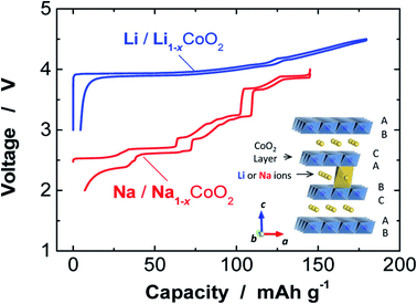 |
| | Fig. 4 Comparison of charge/discharge plots of Na/NaCoO2 and Li/LiCoO2 cells. (Adapted from ref. 31, copyright 2014 American Chemical Society). | |
2. Components of battery
There are three main components of battery: electrodes, electrolyte, and separator. They are explained briefly and shown in Table 2.
Table 2 Components of LIBs and SIBsa
| Chemistry |
SIB |
LIB |
| EC = ethylene carbonate, PE = polyethylene, DMC = dimethyl carbonate. |
| Anode |
Hard carbon on foil of aluminium, organic binder |
Graphite on foil of copper, organic or aqueous binder |
| Cathode |
Layered oxide on foil of aluminium, organic binder |
Layered oxide foil of aluminium, organic binder |
| Separator |
Polymer film (mostly PE) |
Polymer film (mostly PE) |
| Electrolyte |
Na salt (NaPF6, NaClO4)in organic solvent (EC/DMC) |
Li salt (LiPF6, LiTFSI) in organic solvent (EC/DMC) |
| Cell housing |
Prismatic, pouch, or round cells |
Pouch, prismatic, or round cells |
2.1 Electrodes
Anode and cathode are the two electrodes which contribute to the storage of energy. Anode is the electrode of a battery that loses electrons and cathode is the electrode that gains electrons while discharging. These electrodes should have ionically as well as electronically conductive and chemically compatible with the electrolyte. There are different types of cathode materials for SIBs which are discussed in detail in below section. Also, the anode materials can be categorized into carbons, metals and alloys, low potential TMOs and phosphates.
2.2 Electrolyte
Electrolyte is the medium between the two electrode polarities of a cell that provides ionic conductivity. Electrolytes are an essential element of all electrochemical devices. In most electrochemical devices such as batteries, aqueous solutions of acids and salts are used as electrolytes. Aqueous solutions are convenient, easy to prepare, and should be made from relatively inexpensive and readily available materials. If the electrolyte has electronic conductivity, it can give rise to self-discharge, and an internal short-circuit would occur within the cell.35 When there is a surplus of liquid electrolytes, the term used is the flooded-electrolyte battery. Still, if the liquid electrolyte is fully immobilized within the separator, it is referred to a starved-electrolyte battery.36 Not only lead-acid batteries but also vanadium redox flow batteries and Zn/Br batteries uses active electrolyte which takes part in the half-cell reactions.37 Most batteries, especially those with an aqueous electrolyte, undergo slow self-discharge when left standing on an open circuit. Other ionic conductors like fused salts, polymers, organic salt solutions, and ceramics are used as electrolytes. Purification of the electrolyte solutions is crucial, especially concerning separating the last traces of water.38 Electrolyte works as a path provider for positive ions moving from cathode to anode while charging and that from anode to cathode while discharging. Ions are electrically charged atoms that have gained or lost electrons.
The electrolyte should have zero electronic and high ionic conductivity to prevent short-circuiting of the electrons, high thermodynamic stability in a wide voltage and temperature range, and high chemical and physical compatibility with anode and cathode.
2.3 Separator
The separator is an essential component of the battery that separates the negative electrode and positive electrode in the battery to prevent the negative and positive electrodes from direct contact, which may cause a short circuit.39 It has a porous structure to give a passage for the ions, realizing ions transportation between the positive and negative electrodes. The separator has no participation in the battery's reaction, although it shows a crucial role in the battery. The separator influences safety performance, battery capacity, cycle performance, and rate performance to some extent.40 Currently, non-woven fabric separators and polyolefin separators are generally utilized commercially. The chief factors of the separator involve mechanical strength, chemical stability, wettability, heat resistance, and porosity.34 Analyzing the earlier factors to choose the suitable separator material, rechargeable battery separators are principally classified into polyolefin-based separators, ceramic composite separators, and non-woven separators. Various formation processes and the replacement of the separator's function have been directed to some latest types of separators, like polymer electrolyte separators.
3. Working of sodium ion battery
In charging, sodium ions are extracted from the positive electrode and passed by an electrolyte, reached into the negative electrode. When the current flow in an external circuit, the battery discharges spontaneously, i.e., on the anode, the oxidation reaction occurs, related to the sodium ions departs from the structure of the negative electrode and reached into the layers of the cathode. A rechargeable Na+ ion cell consists of two materials capable of Na+ ion insertion called negative electrode and positive electrode. The electrolyte (pure ionic conductor) electronically isolates these electrodes. The stored chemical energy is converted into electrical energy, and the performance of the entire assembly changes with varying the shape, state, composition, alignment of these components. A representation of the operating principle of SIBs is shown in Fig. 5.
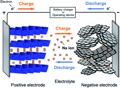 |
| | Fig. 5 Schematic showing the working principle of the sodium ion battery. (Adapted from ref. 31, copyright 2014 American Chemical Society). | |
In secondary battery technologies, when sodium replaces lithium, it requires completely new anode materials. The most remarkably suitable anode material, graphite in LIB, is incapable of intercalating sodium metal ions between its nanosheets. Hard carbon or no graphitizable carbon, which can intercalate sodium ions are used an anode material in SIBs.41–43 The overall chemical reaction for charging and discharging of NaMnO2 is shown below:
While charging,
| At cathode: NaMnO2 → Na1−xMnO2 + xNa+ + xe− |
| At anode: C + xNa+ + xe− → NaxC |
| Overall: C + NaMnO2 → Na1−xMnO2 + NaxC |
While discharging,
| At cathode: Na1−xMnO2 + xNa+ + xe− → NaMnO2 |
| At anode: NaxC → C + xNa+ + xe− |
| Overall: Na1−xMnO2 + NaxC → NaMnO2 + C |
4. Cathode materials for SIBs
The cathode materials for SIBs are categorized into four types viz. layered transition metal oxides,44 polyanionic compounds,45 Prussian blue (PB) analogues and organic compounds as shown in Fig. 6. PBs are deficient for Na+ storage because of the vacancies present. During process of de/intercalation, Fe–C![[triple bond, length as m-dash]](https://www.rsc.org/images/entities/char_e002.gif) N–Fe bond disrupts which results in lattice distortion. It is a challenge to synthesize PBs at room temperature having high efficiency.46–48 Polyanionic cathode materials provides better safety and they are non-hygroscopic in nature but they exhibit poor cycling performance.49 Layered transition metal oxides (TMOs) NaxMO2 (here, M = transition metals, can be single or multiple metal elements) are expected to be promising cathode materials for SIBs. The specific structure has small ion diffusion channels and a bigger surface area during sodiation/desodiation that are advantageous for stabilizing cycling capacity.50–53 The prosperity of LiCoO2 unsurprisingly inspires research into its sodium equivalent, NaCoO2. Layered sodium oxide materials can be categorized based on the position of Na+ ions. The terminology for these materials is as follows: P and O refer to Na's trigonal and octahedral coordination, and the number 3 or 2 refers to the repetition of layers of transition metal in the unit cell. For example, in O3, it's ABCABC, and in P2, it's ABBA, as illustrated in Fig. 7. The withdrawal of sodium ions from O3 and P2-type phases of NaMO2 (M = Fe, Ni, Co, Mn) compounds mostly drives phase transitions.54,55
N–Fe bond disrupts which results in lattice distortion. It is a challenge to synthesize PBs at room temperature having high efficiency.46–48 Polyanionic cathode materials provides better safety and they are non-hygroscopic in nature but they exhibit poor cycling performance.49 Layered transition metal oxides (TMOs) NaxMO2 (here, M = transition metals, can be single or multiple metal elements) are expected to be promising cathode materials for SIBs. The specific structure has small ion diffusion channels and a bigger surface area during sodiation/desodiation that are advantageous for stabilizing cycling capacity.50–53 The prosperity of LiCoO2 unsurprisingly inspires research into its sodium equivalent, NaCoO2. Layered sodium oxide materials can be categorized based on the position of Na+ ions. The terminology for these materials is as follows: P and O refer to Na's trigonal and octahedral coordination, and the number 3 or 2 refers to the repetition of layers of transition metal in the unit cell. For example, in O3, it's ABCABC, and in P2, it's ABBA, as illustrated in Fig. 7. The withdrawal of sodium ions from O3 and P2-type phases of NaMO2 (M = Fe, Ni, Co, Mn) compounds mostly drives phase transitions.54,55
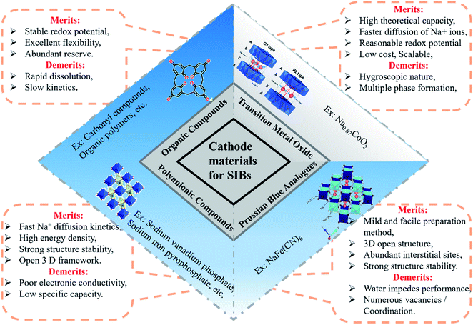 |
| | Fig. 6 Schematic illustration of types of cathode materials for SIB. | |
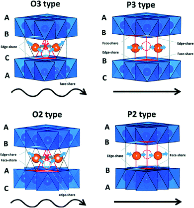 |
| | Fig. 7 Na+ migration paths in different layered structures. (Adapted from ref. 31, copyright 2014 American Chemical Society). | |
Comparison of specific capacity and cycle number for material Na0.44MnO2 made by various processes as cathodes for sodium-ion batteries presented in Fig. 8. Although the highest energy density can be determined for Li-ion cathodes, various Na ion cathodes showing values that make them prospective candidates. The graphical representation also spotlights the obstacle of finding improved Na-ion cathodes. TMOs normally possess high reversible capacities. The compact structural framework of metal oxides makes them ideally appropriate for applications that requires a high volumetric density.56
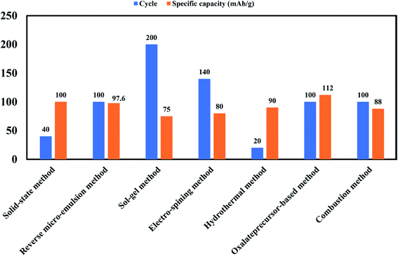 |
| | Fig. 8 Bar chart showing comparison of specific capacity and cycle number for material Na0.44MnO2 made by various processes as cathodes for sodium-ion batteries. | |
4.1 O3-type transition metal oxides
Edge-shared octahedral sites are the initially stabilized site for sodium ions in O3-type structures. Prismatic positions get energetically stable when Na+ ions are partially pulled out from the O3 phase. The gliding of layers of MO2 can accomplish this without breaking M–O bonds. P3-type material can be formed by varying the packing of oxygen in the structure. The transition between the P3/O3-type and P2-type phase is not possible in Na cells and can only be attained by reforming and breaking M–O bonds in a high-temperature surrounding. At the time of the sodium intercalation process, the O3 phase always transforms to the P3 phase. Generally, O3-type materials have more Na content than P2-phase materials.57 O3 based systems are associated with the best battery capacity performances that have the higher sodium stoichiometry.58
Kubota, Kei et al. reported effect of Ti and Mg doping in NaNi1/2Mn1/2O2 (O3 type layered oxide) on phase transition and reversibility during electrochemical intercalation of sodium ions. The structure of NaNi1/2Mn1/2O2 is O3 type layered oxide and it is same as α-NaFeO2, has drawn interest as a cathode material for SIBs due to its larger reversible capacity of 200 mA h g−1.59 The O3 type NaNi1/2Mn1/2O2 materials with Ti or Mg substitution show good capacity, and co-substituted Ti and Mg material shows a discharge capacity of 200 mA h g−1 with no loss of capacity owing to substitution. Replacement of Ti4+ and Mg2+, (bigger ions than Mn4+ or Ni2+), outcomes a greater in-plane lattice of the O3 type structure, this could postpone the transition of phase in charging. The coexistence of Ti and Mg improves the reversibility and the structural stability at the surface of material, rising in the performance of SIB.60,61
The samples of Ti-sub, Ti–Mg-sub, Mg-sub and non-sub (sub for substituted) are shown in Fig. 9(a) using powder synchrotron XRD. For layered oxide phases of the O3 type and R![[3 with combining macron]](https://www.rsc.org/images/entities/char_0033_0304.gif) m space group, indexing of the Bragg's diffraction peaks is carried out. SEM was used to examine the particle's morphology, as shown in Fig. 9(b). All the samples exhibit nearly the similar morphological characterization. Particles of about hundred nanometres in diameter are homogeneously accumulated. Fig. 10(a) demonstrates galvanostatic discharge/charge plot in the broad voltage limit (2.2–4.5 V) for the initial 20 cycles at 12 mA g−1 current density. Ti-substituted and Mg-substituted electrodes give marginally reduced discharge capacities of 185 mA h g−1 compared to 202 mA h g−1 for non-substituted at the first cycle. Ti–Mg-substituted provides a high reversible capacity (198 mA h g−1), that is nearly equal to non-substituted. Ti- or Mg-substituted materials provide marginally lesser reversible capacities (185 mA h g−1) and show better capacity in non-aqueous Na cells than non-substituted. The Ti and Mg co-substituted material shows a larger first discharge capacity (200 mA h g−1).60 As reported by Kubota Kei et al. the initial coulombic efficiency of Mg-substituted and non-substituted electrodes shows nearly the similar value (80%) but Ti-substituted electrode displays marginally reduced efficiency (76%). Ti–Mg-substituted electrode shows the maximum efficiency of 86%. Ti–Mg-substituted and Ti-substituted shows sloping voltage profiles while Mg-substituted and non-substituted samples displays stepwise voltage profiles which are clearly examined as redox peaks in the differential plots in Fig. 10(b). Ti-substituted and Mg-substituted electrodes shows enhanced cyclic stability for 50 cycles with 60% of the first discharge capacities that is 27% more than non-substituted. The co-substitution shows improved cyclic performance. At the 50th cycle, the Ti–Mg-substituted electrode gives 70% of the first discharge capacity. Similar substantial development is detected for Ti and Cu co-substituted62–64 and Ti and Zn co-substituted Na[Ni1/2Mn1/2]O2.65 Therefore, dual substitution with a divalent metal ion and a tetravalent titanium ion, that contains not only Zn2+ and Cu2+ ions but also Mg2+ ion, is more effective in refining the electrochemical characteristics of Na[Ni1/2Mn1/2]O2 and meaningly improves cycle stability even in the region of high potential (>4.0 volts vs. Na+/Na). The outcomes informed by Kubota Kei et al. suggest that Ti and Mg co-substitution stabilizes layered oxide structures in both surface and bulk. Mg-substitution would be helpful as a HF scavenger, defending the particle surface to counter the harm of electrolyte.66 The replacement only of Mg2+ and only of Ti4+ results in small enhancement of cycle stability Fig. 10(c).
m space group, indexing of the Bragg's diffraction peaks is carried out. SEM was used to examine the particle's morphology, as shown in Fig. 9(b). All the samples exhibit nearly the similar morphological characterization. Particles of about hundred nanometres in diameter are homogeneously accumulated. Fig. 10(a) demonstrates galvanostatic discharge/charge plot in the broad voltage limit (2.2–4.5 V) for the initial 20 cycles at 12 mA g−1 current density. Ti-substituted and Mg-substituted electrodes give marginally reduced discharge capacities of 185 mA h g−1 compared to 202 mA h g−1 for non-substituted at the first cycle. Ti–Mg-substituted provides a high reversible capacity (198 mA h g−1), that is nearly equal to non-substituted. Ti- or Mg-substituted materials provide marginally lesser reversible capacities (185 mA h g−1) and show better capacity in non-aqueous Na cells than non-substituted. The Ti and Mg co-substituted material shows a larger first discharge capacity (200 mA h g−1).60 As reported by Kubota Kei et al. the initial coulombic efficiency of Mg-substituted and non-substituted electrodes shows nearly the similar value (80%) but Ti-substituted electrode displays marginally reduced efficiency (76%). Ti–Mg-substituted electrode shows the maximum efficiency of 86%. Ti–Mg-substituted and Ti-substituted shows sloping voltage profiles while Mg-substituted and non-substituted samples displays stepwise voltage profiles which are clearly examined as redox peaks in the differential plots in Fig. 10(b). Ti-substituted and Mg-substituted electrodes shows enhanced cyclic stability for 50 cycles with 60% of the first discharge capacities that is 27% more than non-substituted. The co-substitution shows improved cyclic performance. At the 50th cycle, the Ti–Mg-substituted electrode gives 70% of the first discharge capacity. Similar substantial development is detected for Ti and Cu co-substituted62–64 and Ti and Zn co-substituted Na[Ni1/2Mn1/2]O2.65 Therefore, dual substitution with a divalent metal ion and a tetravalent titanium ion, that contains not only Zn2+ and Cu2+ ions but also Mg2+ ion, is more effective in refining the electrochemical characteristics of Na[Ni1/2Mn1/2]O2 and meaningly improves cycle stability even in the region of high potential (>4.0 volts vs. Na+/Na). The outcomes informed by Kubota Kei et al. suggest that Ti and Mg co-substitution stabilizes layered oxide structures in both surface and bulk. Mg-substitution would be helpful as a HF scavenger, defending the particle surface to counter the harm of electrolyte.66 The replacement only of Mg2+ and only of Ti4+ results in small enhancement of cycle stability Fig. 10(c).
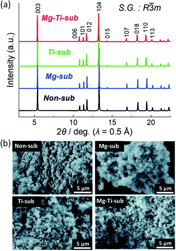 |
| | Fig. 9 (a) X-ray diffraction patterns and (b) SEM images of pristine Na[Ni4/9Mn1/3Mg1/18Ti1/6]O2 (Mg–Ti-sub), Na[Ni1/2Mn1/2]O2 (non-sub), Na[Ni4/9Mn1/2Mg1/18]O2 (Mg-sub) and Na[Ni1/2Mn1/3Ti1/6]O2 (Ti-sub). (Adapted from ref. 59, copyright 2021 Royal Society of Chemistry). | |
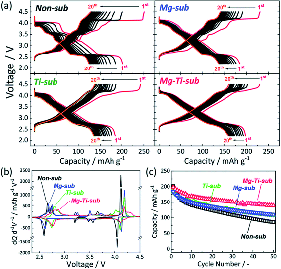 |
| | Fig. 10 (a) Galvanometric charge–discharge plot, (b) dQ/dV plot, and (c) cyclic stability of Mg–Ti-sub, non-sub, Mg-sub and Ti-sub and electrodes in Na-ion cells. At 12 mA g−1 current density galvanostatic charge–discharge experiments were conducted. (Adapted from ref. 60, copyright 2021 Royal Society of Chemistry). | |
Hwang et al. synthesized O3-type Na[Ni0.32Co0.13Fe0.15Mn0.4]O2 cathode material via coprecipitation method. The various characterizations revealed that quaternary transition metal Fe substitution helped to enhance the specific capacity. Quaternary TMO frameworks effectively avoid the dissolution of transition metal during cycling. This compound displayed higher specific capacity with excellent cycling stability.67 This cathode material displayed the good electrochemical properties as shown in Fig. 11.
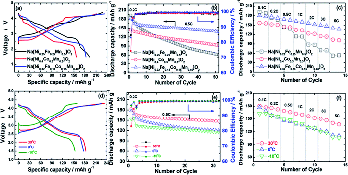 |
| | Fig. 11 (a) First charge–discharge curves at 0.2C rate (30 mA g−1), (b) cycle life test at 0.5C rate (75 mA g−1), and (c) rate capabilities test of Na[Ni0.25Fe0.25Mn0.5]O2, Na[Ni0.4Co0.3Mn0.3]O2, and Na[Ni0.32Fe0.13Co0.15Mn0.40]O2 cathodes in the voltage range of 1.5–4.3 V at 30 °C. (d) First charge–discharge curves at 0.2C rate (30 mA g−1), (e) cycle life test at 0.5C rate (75 mA g−1), and (f) rate capabilities of Na[Ni0.32Fe0.13Co0.15Mn0.40]O2 cathodes at various operating temperatures from −10 to 30 °C. For a rate capability test, all cells were charged to 4.3 V with a constant C rate of 0.1C (15 mA g−1) and then discharged to 1.5 V with a different C rate ranging from 0.1C (15 mA g−1) to 5C (750 mA g−1). (Adapted from ref. 67, copyright 2018 American Chemical Society). | |
The other transition metals such as Ti and Zr maximize the electronic delocalization and entropy of mixing resulting in the improved structural stability. This type of doping elements enhances the electrochemical properties in terms of reversible specific capacity ∼141.4 mA h g−1.68 It is concluded from recent studies that the doping and substitution of transition elements to the TMOs effectively improves the performance of the SIBs.69–71
4.2 P2-type transition metal oxides
Layered P2-type compounds have exhibited increased electrochemical properties as, in general, they experience fewer phase transitions when de/intercalating Na+ ions than O3-type compounds.73 For the P2 phase, it is much easier to maintain its original structure. The electrochemical results suggest that the P2 phase shows better cycling stability and rate capability than the P3 phase.74 Fig. 7 shows Na+ migration paths in different layered structures. Many O3 and P2 layered materials have been examined as they are potentially used as the cathode. O and P, respectively refer the coordination of elongated octahedral and trigonal prismatic sites of Na-ion between sheets of metal-oxide (MO2). Assuming stacking of the sheets normal to Z-direction, three possible positions can be occupied by the oxygen atoms in the XY plane of each layer, designated A, B, and C. All the MO2 sheet has two layers of oxygen atoms which is paired below and above the metal layer.75
Palm, R. et al. synthesized polycrystalline Na0.5MgxNi0.17−xMn0.83O2 (x = 0.07, 0.05, 0.02 and 0) via solid state method. The structure of crystal and quality of samples were validated using XRD analysis in Fig. 12. Fig. 13 displays the galvanostatic characteristics of the various samples examined at 0.1C in the voltage limit of 2–4.5 V. Fig. 13(a) displays undoped P2–Na0.5Ni0.17Mn0.87O2, three peaks at 4.2 V, 3.7 V and 2.8 V. The initial charge capacity was 150 mA h g−1, equivalent to 0.55 sodium extraction hypothetically, that is higher than the initial content of sodium from the chemical formula.76 Various reasons describe the extra capacity: at high value of voltages, the sample suffers a conversion of phase from P2 type to the O2 type phase,77 yielding high capacity; due to the oxygen redox contribution the additional capacity is produced,78–81 and electrolyte decay at high range of voltage.82 With continuous cycling, the peak above 4.2 V vanished, which specifies procedures at high value of voltages decline because of their instability and irreversibility. Fig. 13(b)–(d) displays the galvanostatic cycling performance of the samples with several doping of Mg, x = 0.07, 0.05 and 0.02. Fig. 13(e) illustrates an evaluation of the specific capacity and cyclability. Usually, all Mg-doped materials have a better retention of capacity compared to the sample without doping, that is because of the stable development of the reversible OP4 phase at elevated voltages than with the permanent O2 phase development in the material with no doping.81,83 The doping x = 0.02 shows the lowermost fading of capacity, while also demonstrating the maximum specific capacity among all samples. Various studies show even a minute Mg replacement has a powerful impact on the gross performance of P2-phase Na0.5MgxNi0.17−xMn0.83O2. Particularly, the Mg replacement of x = 0.02 is the highly favourable configuration because of its maximum redox reversibility because of the highest differences in potential, highest capacity retention and the maximum mobility of Na-ion. By Rietveld refinement of the XRD data for the x = 0.02 sample, it can be observed that minor impurity phases (≤5%) most likely corresponding to nickel and manganese oxide compounds, which could partially come from unreacted synthesis starting materials (NiO and MnO). The starting materials are marked by blue (NiO, hexagonal) and orange (MnO, hexagonal) arrows, respectively and represent possible compounds.
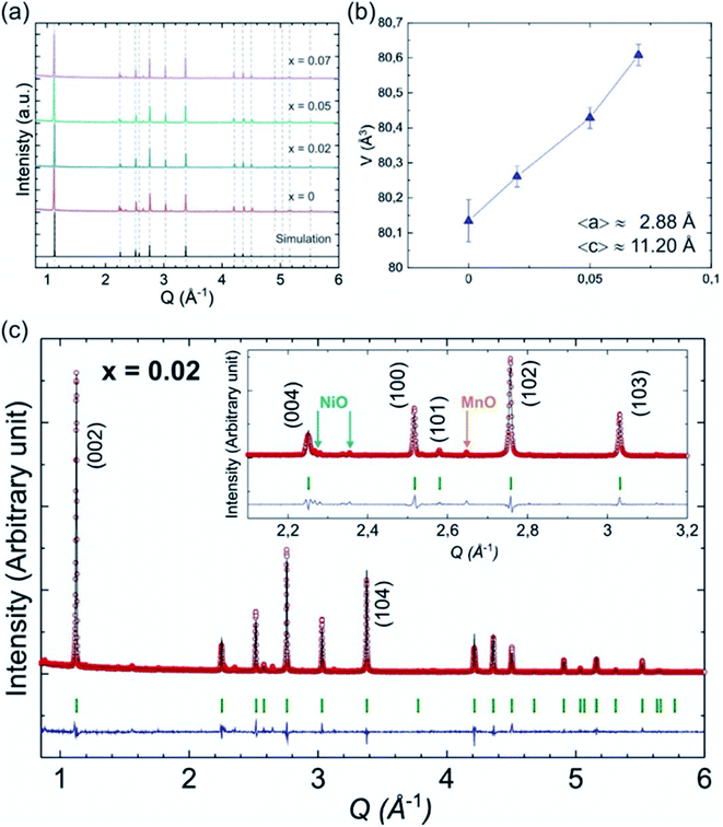 |
| | Fig. 12 (a) XRD pattern of P2-type Na0.5Mn0.83MgxNi0.17−xO2 (x = 0.07, 0.05, 0.02 and 0) samples together with a simulated pattern based on x = 0 structure. (b) Cell volume for different Mg content (x) along with the average lattice parameters 〈a〉 and 〈c〉. (c) Rietveld refinement of the XRD data for the x = 0.02 sample. (Adapted from ref. 72, copyright 2021 Royal Society of Chemistry). | |
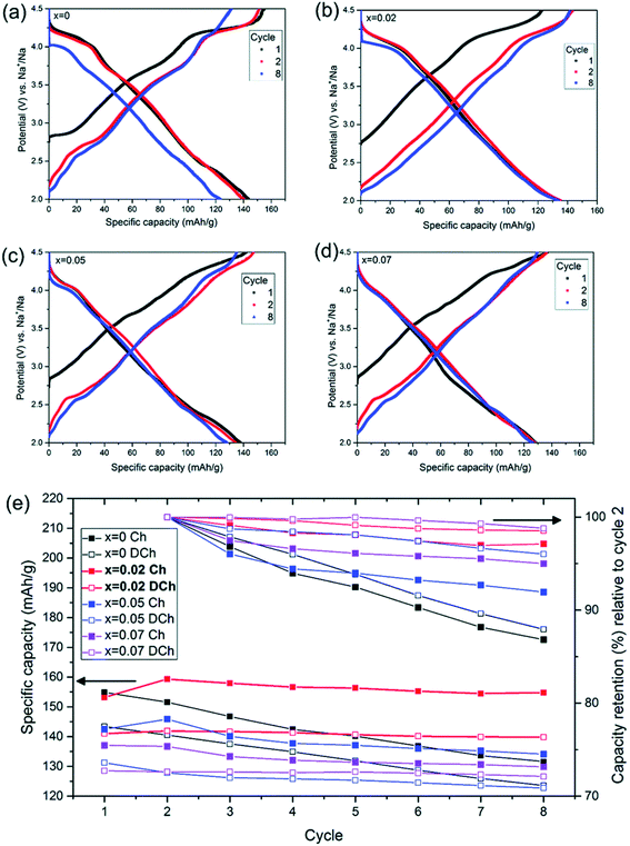 |
| | Fig. 13 Galvanostatic charge discharge examined at 0.1C in the voltage of 2–4.5 V for P2–Na0.5MgxNi0.17−xMn0.87O2 by using NaPF6 in PC as the electrolyte with various Mg contents (x = 0–0.07). Galvanostatic charge/discharge plot of (a) Na0.5Ni0.17Mn0.87O2, (b) Na0.5Mg0.02Ni0.15Mn0.87O2, (c) Na0.5Mg0.05Ni0.12Mn0.87O2 and (d) Na0.5Mg0.07Ni0.10Mn0.87O2. (e) Cycle number vs. capacity. (Adapted from ref. 72, copyright 2021 Royal Society of Chemistry). | |
In Fig. 14 the Ni atoms will be replaced by Mg atom into the 2a lattice sites. The fractional (2d) site occupancy is represented by the yellow partial colouring of the Na atom. Also, the existence of two different sites: Na2 (2d) and Na1 (2b) are verified.
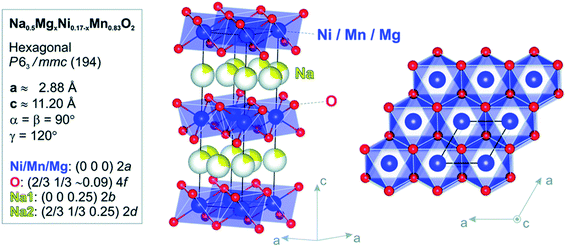 |
| | Fig. 14 Model of atomic structure (side-view and top-view) and the atomic positions and crystallographic constraints for Na0.5Mn0.83MgxNi0.17−xO2 calculated by Rietveld refinement study of the RTXRD pattern based on the structure of x = 0 sample. (Adapted from ref. 72, copyright 2021 Royal Society of Chemistry). | |
In Fig. 15 the potential difference Ediff peak value with the highest current value between the discharge and charge cycle, 4.2 V vs. Na+/Na, are represented with respect to the number of cycles. The value of Ediff can give understanding into the redox process reversibility. At more Ediff value, the more the redox procedure will be more irreversible.
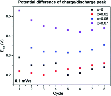 |
| | Fig. 15 Inspection from cyclic voltammetry data at scan rate 0.1 mV s−1. (Adapted from ref. 72, copyright 2021 Royal Society of Chemistry). | |
The lithium doped TMO was successfully synthesized by Yang's group. P2–Na0.66Li0.18Fe0.12Mn0.7O2 displayed high capacity of 190 mA h g−1 with ∼87% capacity retention over 80 cycles.84 The stability is ascribed to the reversible migration of lithium while cycling and reduction of P2–O2 transformation.85,90 The appropriate sodium content is important to achieve remarkable electrochemical performance. P2-type cathode-Na0.85Li0.12Ni0.22Mn0.66O2 containing high sodium content exhibited plateau-free and fast Na+ mobility with low volume expansion (∼1.7%). This material delivered 123.4 mA h g−1 capacity with outstanding rate capability and 85.4% capacity was retained over 500 cycles.86,87 Recently, the metal–organic frameworks (MOFs) based layered TMOs were developed which is the cost-effective synthesis method for high performance cathode materials as shown in Fig. 16. The homogeneous distribution of atoms in MOFs allows fast phase transition during calcination. This show outstanding electrochemical performance. NaxMnO2 synthesized using MOF precursor demonstrated the high specific capacity of 212 mA h g−1 with capacity retention of 84% over 100 cycles.88 Besides, P2–Na0.7Li0.03Mg0.03Ni0.27Mn0.6Ti0.07O2 exhibited high reversible specific capacity and excellent cyclic stability. This was due to the contribution of Ti, Mg and Li which provides high redox potential, structural stability, and smoothening of electrochemical curves respectively. Finally this was concluded that strategy of doping the elements is the rationale route to improve the electrochemical performance of the cathode material.89
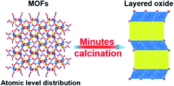 |
| | Fig. 16 Schematic illustration of the preparation method of MOF based TMO cathode material. (Adapted from ref. 88, copyright 2022 American Chemical Society). | |
4.3 O/P biphasic type transition metal oxides
The electrochemical performance of the O, the P, and the O/P-phase samples were analysed by Wang Kai et al. using CV as shown in Fig. 17(a) and (b). The CV plot of the P2-phase sample shows two well-specified oxide peaks at about 3.7 and 2.4 V, relating to Mn3+/4+ and Ni2+/3+ transition. Additionally, the space between the Mn3+/4+ redox peaks is moved to greater voltage than the P2 type sample related to a greater energy density of the O3 type sample. The biphasic sample shows greater shift of the reduction and oxidation peaks towards a greater voltage Fig. 17(c). Broad and smooth peaks after 1st cycle are a strong signal of a solid-state reaction and greater energy density of the O/P two phase materials than the single-phase P2 type material. The cycling characteristics of the materials is displayed in Fig. 17(d) and (e). The O/P two phase sample displays the finest cycling properties. Even though, the pure P2-phase sample has a greater first discharge capacity compared to the pure O3-phase sample, the lower cycling stability outcomes in inadequate retention of capacity. Primarily, a distinct reduction of the reversible capacity of the O/P two phase sample is identified.90
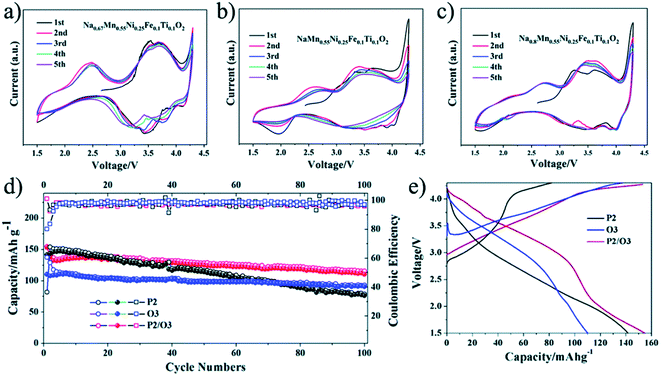 |
| | Fig. 17 (a) CV plot of P2, (b) CV plot of O3, and (c) CV plot of O/P two phase sample; (d) capacity vs. cycle number plot of the samples and (e) voltage-first discharge capacity plots. (Adapted from ref. 90, copyright 2021 Royal Society of Chemistry). | |
Wang Kai et al. reported synthesis of intergrown O/P-type two-phase layered oxides as high-performance cathode for SIBs. Two phase Na0.8MnyNi0.8−yFe0.1Ti0.1O2 (y = 0.45, 0.5, 0.55, 0.6) positive electrode materials are prepared by solid-state method. Electrochemical experiments of the prepared sample reveal improved characteristics of the O/P two phase materials in a SIBs than single O3 or P2 phases, confirming the advantageous outcome of the intergrowth of O3 and P2 materials. All O/P two phase composites Na0.8MnyNi0.8−yFe0.1Ti0.1O2, (y = 0.45, 0.5, 0.55, 0.6), P2-type Na0.67Mn0.55Ni0.25Fe0.1Ti0.1O2, and O3-type NaMn0.55Ni0.25Fe0.1Ti0.1O2 materials were synthesized by a solid-state method. The Mn to Ni ratio of the Na0.8MnyNi0.8−yFe0.1Ti0.1O2 was changed, with y = 0.45, 0.5, 0.55, 0.6. Fig. 18(a) displays the XRD pattern analysis of the various samples, verifying the existence of both O3 and P2 phases, collectively with the preferred two-phase composition, Na0.8Mn0.55Ni0.25Fe0.1Ti0.1O2. Disparity in the ratio of O3/P2 two phase materials will also affect the electrochemical characteristics. Fig. 18(b) displays the cyclic performances of the different samples. Even though three mixed O/P phases have better first discharge capacity than single-phase material, after 10 number of cycles the greatest retention of discharge capacity is seen for Na0.8Mn0.55Ni0.25Fe0.1Ti0.1O2. Therefore, the Na0.8Mn0.55Ni0.25Fe0.1Ti0.1O2 is most favourable two-phase material in this series.90 The diffraction pattern of the Na0.67Mn0.55Ni0.25Fe0.1Ti0.1O2 sample shows the existence of a pure P2 type phase, which fits nicely with the general P2 type structure for the synthesized sample. For O3-phase NaMn0.55Ni0.25Fe0.1Ti0.1O2, there are little peaks of impurity in the XRD pattern of material that might be the outcome of some impurities of TMOs or other layered type structures difficult to detect individually because of their low reaction concentrations. The XRD pattern of the two-phase material includes the peaks of both the O3 and P2 phases that fit to the space groups R![[3 with combining macron]](https://www.rsc.org/images/entities/char_0033_0304.gif) m and P63/mmc. High crystallinity of the material is signified by the sharp peaks in the XRD pattern. The two-phase material gives higher capacity than the P2-phase material after 20 cycles owing to its improved cycling stability. After the 76th cycle, the pure O3-phase sample also shows a greater capacity compared to the P2-phase material. The O/P intergrown Na0.8Mn0.55Ni0.25Fe0.1Ti0.1O2 structure demonstrated a capacity retention of 80.2% keeping 110 mA h g−1, after 100 cycles that is much greater compared to the pure P2-phase sample (almost 53.8%). After 100 cycles, the first discharge capacity of the O3 phase sample is less (97 mA h g−1) owing to its less initial discharge capacity. The O/P two phase material showed the greatest energy density of 451 W h kg−1 owing to the higher voltage and reversible capacity. Furthermore, the O/P two phase material showed well rate performance than the O3- and P2-phase materials. Fig. 17(e) displays the first charge–discharge plots of the materials. The initial charge capacity of the P2-phase sample is 82 mA h g−1, that is far lesser compared to the subsequent discharge capacity of 142 mA h g−1. The first charge capacity of for the pure O3-phase material 138 mA h g−1 that is greater than the corresponding discharge capacity of 110 mA h g−1, that can be associated to its adequate sodium reserves. Expectedly, the O/P phase material provided the greatest initial discharge capacity of almost 153 mA h g−1. Furthermore, the charge–discharge plots display that O/P two phase Na0.8Mn0.55Ni0.25Fe0.1Ti0.1O2 demonstrated greater voltage of discharge with better energy density compared to the pure phases. A greater reversible capacity of 154.6 mA h g−1 with good initial coulombic efficiency of the two-phase material achieved with an outstanding retention in capacity (80.2%) at 0.1C after 100 cycles. Furthermore, the O/P biphasic material showed greater energy density and greater rate performance compared the pure O3 and P2 phases. The excellent electrochemical characteristic of the two-phase sample is ascribed to the harmonious properties between the intergrown O3 and P2 phases improving both ion mobility and stability.82 The plot of various TMOs are summarized in terms of capacity, energy density and average voltage in Fig. 19.
m and P63/mmc. High crystallinity of the material is signified by the sharp peaks in the XRD pattern. The two-phase material gives higher capacity than the P2-phase material after 20 cycles owing to its improved cycling stability. After the 76th cycle, the pure O3-phase sample also shows a greater capacity compared to the P2-phase material. The O/P intergrown Na0.8Mn0.55Ni0.25Fe0.1Ti0.1O2 structure demonstrated a capacity retention of 80.2% keeping 110 mA h g−1, after 100 cycles that is much greater compared to the pure P2-phase sample (almost 53.8%). After 100 cycles, the first discharge capacity of the O3 phase sample is less (97 mA h g−1) owing to its less initial discharge capacity. The O/P two phase material showed the greatest energy density of 451 W h kg−1 owing to the higher voltage and reversible capacity. Furthermore, the O/P two phase material showed well rate performance than the O3- and P2-phase materials. Fig. 17(e) displays the first charge–discharge plots of the materials. The initial charge capacity of the P2-phase sample is 82 mA h g−1, that is far lesser compared to the subsequent discharge capacity of 142 mA h g−1. The first charge capacity of for the pure O3-phase material 138 mA h g−1 that is greater than the corresponding discharge capacity of 110 mA h g−1, that can be associated to its adequate sodium reserves. Expectedly, the O/P phase material provided the greatest initial discharge capacity of almost 153 mA h g−1. Furthermore, the charge–discharge plots display that O/P two phase Na0.8Mn0.55Ni0.25Fe0.1Ti0.1O2 demonstrated greater voltage of discharge with better energy density compared to the pure phases. A greater reversible capacity of 154.6 mA h g−1 with good initial coulombic efficiency of the two-phase material achieved with an outstanding retention in capacity (80.2%) at 0.1C after 100 cycles. Furthermore, the O/P biphasic material showed greater energy density and greater rate performance compared the pure O3 and P2 phases. The excellent electrochemical characteristic of the two-phase sample is ascribed to the harmonious properties between the intergrown O3 and P2 phases improving both ion mobility and stability.82 The plot of various TMOs are summarized in terms of capacity, energy density and average voltage in Fig. 19.
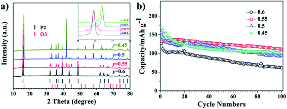 |
| | Fig. 18 (a) XRD patterns of Na0.8MnyNi0.8−yFe0.1Ti0.1O2 (y = 0.45, 0.5, 0.55, 0.6). (b) Cycling performance of Na0.8MnyNi0.8−yFe0.1Ti0.1O2 (y = 0.45, 0.5, 0.55, 0.6). (Adapted from ref. 90, copyright 2021 Royal Society of Chemistry). | |
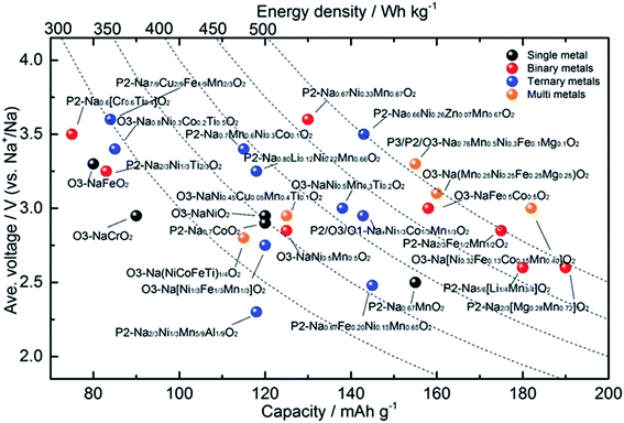 |
| | Fig. 19 An electrochemical summary of various layered oxide sodium-ion cathode materials, comparing voltage, capacity and energy density. (Adapted from ref. 91, copyright 2020 Wiley Online Library). | |
4.4 Other type transition metal oxides
Along with the layered TMOs, mono-layered, spinel and tunnel structured metal oxides also exhibit remarkable electrochemical performance. Even so, mono-layered TMOs belong to the superlattice ordering system.92
Fig. 20 represents the charge/discharge profiles displayed by these materials which shows multiple voltage plateaus that associated with the cycle performance of the cathode materials. Solid solution TMOs shows that lattice parameters vary linearly with the Na content. However, they exhibit excellent electrochemical performance due to presence of the P-type and O-type structures. Recently, these materials are proposed for SIBs. Monoclinic NaMnO2 displayed good electrochemical properties determined with computational method as well as experimentally.94 Noha Sabi et al. synthesized Ti substituted NaCoO2 and delivered initial charge capacity of 108 mA h g−1 with remarkable cyclic stability. This study gave insights about the sodiation/desodiation mechanism of the this compounds showed the effect of inactive doping in the oxide material.95 Some studies reported that the mono-layers of the transition metal carbides/nitrides (MXenes) enhances the accessibility to the surface.96 The study has revealed that MXenes exhibit excellent electrochemical performance due to its exceptional properties such as electrical conductivity, thermal stability and mechanical strength.97
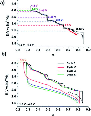 |
| | Fig. 20 Galvanostatic cycling curve of a Na//P2–NaxCoO2 battery representing the phase diagram. (Adapted with permission from ref. 93, copyright 2022 American Chemical Society). | |
High operating voltage, thermal stability and good specific capacity make spinel-like LiMn2O4 a promising cathode material for LIBs. But, analogous spinel-like NaMn2O4 is challenging as it is thermally instable. They transform spinel to post-spinel structure at high pressure offering new pathway for application in rechargeable battery cathodes.98 NaVSnO4 post-spinel crystal structure composed of VO6 and SnO6 octahedrons of metal oxides as shown in Fig. 21.99
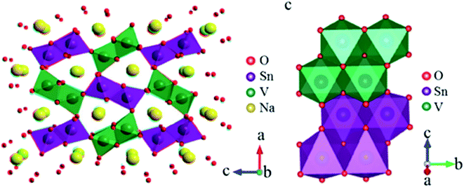 |
| | Fig. 21 Crystal structure of post-spinel NaVSnO4. (Adapted with the permission from ref. 100, copyright 2017 Wiley Online Library). | |
Apart from these crystal structures, tunnel-type TMOs (Fig. 22) have been extensively studied for SIB application. The NaxMnO2 tunnel oxide attracted much attention as Na+ insertion host for Mn based TMOs with less Na content. It offers higher structural stability as well as Na+ diffusion rate compared to layered TMO NaxMnO2.101 But, the intercalation potential of these material is low. This leads to the substitution of element at transition metal site as effective way to get desirable properties of the cathode compounds.102
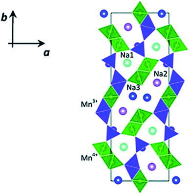 |
| | Fig. 22 Crystal structure of tunnel-type Na0.44 MnO2. (Adapted with the permission from ref. 103, copyright 2022 Royal Society of Chemistry). | |
The single-phase material frequently exhibits constrained and imbalanced electrochemical properties, even though layered materials are promising cathodes for rechargeable SIBs. For instance, the P2 structure's wide, triangularly shaped Na-ion transport channel exhibits low migration energy barrier and good rate performance, but the structure's unfavourable Na/vacancy ordering and P2–O2 phase transition result in poor structural stability and worse capacity retention.104 The O3 structure has various drawbacks, including low air stability, difficult phase transitions, and a high energy barrier for Na diffusion. Nevertheless, it is a sufficient Na-ion storage that can feed enough Na ions to a full cell. The tunnel structure has favourable kinetic dynamics and strong structural stability, however major improvement is required for its small capacity. To concentrate advantages and overcome disadvantages of the single-phase material to attain good detailed electrochemical characteristics, composite-structure materials (CSMs) that mix two or more crystal structures have garnered considerable interest. The two types of CSMs under investigation are layered-tunnel CSMs and layered–layered CSMs.105,106
Some of the existing and upcoming challenges related to layered SIBs are connected to the development of high performing cathode materials. Still, the added possibility afforded by the two different environments of sodium inside the O3|P2 layered materials consequence in extra complexities of structures upon cycling of battery. A basic and comprehensive understanding of this structural development over thousands of cycles is essential for the improvement of cycling, increased lifetime performance and to mitigate degradation. Notable variations in performance can result from small replacements and some of them are reviewed in Table 3. P2-based systems can meet the best power performance due to the specific sodium-ion surroundings that permit facile ionic mobility over rectangle-shaped faces between neighbouring trigonal prismatic environments. In LIBs, this diffusion mechanism is unavailable, indicates that the improvement of P2-based SIBs may provide a higher coefficient of diffusion and, accordingly higher rate of discharge and charge than for LIBs.56 There are possibilities to manufacture sustainable green batteries by layered O3|P2 type cathodes made from earth-abundant materials. Table 3 shows the development of TMO (NaMO2) cathode material for SIBs with different types of doping. In this review article, cycle number, voltage range, current density, first discharge capacity and capacity retention of the different phases of materials have been compared. It can be seen from Table 3 that even a small fraction of doping in stoichiometric ratio can change the properties of materials.
Table 3 Development of cathode for SIB
| Composition |
Type |
Voltage (V) |
First discharge capacity [mA h g−1] |
Capacity retention (%), cycle number |
References |
| Na0.6Li0.2Mn0.8O2 |
P2 |
2–4.6 |
190 at 1C |
100, 100 |
107 |
| Na0.45Ni0.22Co0.11Mn0.66O2 |
P2 |
1.5–4.6 |
200 at 0.1C |
80, 100 |
108 |
| Na0.55Ni0.1Fe0.1Mn0.8O2 |
P2 |
1.5–4.3 |
221.5 at 0.1C |
75, 100 |
109 |
| Na0.67Mn0.65Ni0.2Mg0.15O2 |
P2 |
2–4.3 |
125 at 0.1C |
94, 100 |
110 |
| Na2/3Co2/3Mn2/9Ni1/9O2 |
P2 |
2–4.5 |
140 at 0.05C |
85, 10 |
83 |
| Na2/3Ni1/6Mn2/3Cu1/9Mg1/18O2 |
P2 |
2.5–4.15 |
64 at 0.1C |
81.4, 500 |
111 |
| Na[Li0.05(Ni0.25Fe0.25Mn0.5)0.95]O2 |
O3 |
1.75–4.4 |
180 at 0.1C |
90, 20 |
112 |
| Na0.9Ca0.05Ni1/3Fe1/3Mn1/3O2 |
O3 |
2–4 |
127 at 0.1C |
92, 200 |
113 |
| Na0.75Ni0.82Co0.12Mn0.06O2 |
O3 |
2–4 |
171 at 0.1C |
65, 400 |
114 |
| Na4FeRuO6 |
O3 |
2–4 |
120 at 0.2C |
80, 100 |
115 |
| Na0.67Fe0.425Mn0.425Mg0.15O2 |
P2/O3 |
1.5–4.2 |
98 at 0.1C |
95, 50 |
116 |
| Na2/3Li0.18Mn0.8Fe0.2O2 |
P2/O3 |
1.5–4.2 |
125 at 0.1C |
70, 100 |
117 |
| Na0.7Li0.06Mg0.06Ni0.22Mn0.67O2 |
P2/P3 |
2–4.4 |
129 at 0.2C |
97, 50 |
118 |
| Na0.66Mn0.5Co0.5O2 |
P2/P3 |
1.5–4.3 |
156 at 1C |
55, 100 |
119 |
| Na0.6Mn0.75Ni0.25O2 |
P2/P3 |
2–4.1 |
101 at 0.2C |
68, 500 |
120 |
| Na0.66Mn0.9Mg0.1O2 |
P2 |
2–4.5 |
162.9 at 1C |
65, 100 |
121 |
| Na0.8Co0.4Ti0.6O2 |
O3 |
1.1–4 |
100 at 0.1C |
80, 100 |
122 |
| Na2/3[Fe0.22Mn0.78]O2 |
P2 |
1.5–4.3 |
187 at 0.1C |
91, 100 |
123 |
| NaNi0.5Mn0.5O2 |
O3 |
2.2–3.8 |
125 4.8 mA g−1 |
75, 50 |
124 |
| Na2/3Mn0.8Fe0.1Ti0.1O2 |
P2 |
2–4 |
144.16 at 0.1C |
87.7, 300 |
125 |
| Na0.67Cu0.28Mn0.72O2 |
P2 |
2–4.5 |
109 at 0.1C |
98, 50 |
126 |
| Na1.2Mn0.4Ir0.4O2 |
O3 |
1.5–4.4 |
133 at 0.1C |
60, 50 |
127 |
| Na0.67Al0.1Mn0.9O2 |
P2 |
2–4 |
175 12 mA g−1 |
86, 100 |
128 |
| Na2/3[Mn0.8Ni0.2]O2 |
P2 |
2–4.3 |
162 at 0.1C |
75, 100 |
129 |
| Na0.6Ni0.22Al0.11Mn0.66O2 |
P2 |
1.5–4.6 |
252 20 mA g−1 |
80, 50 |
130 |
| NaNi1/3Fe1/3Mn1/3O2 |
O3 |
2–4 |
136 at 0.1C |
80, 100 |
131 |
| Na0.78Al0.05Ni0.33Mn0.60O2 |
P2 |
2–4.5 |
131.9 at 0.1C |
83.9, 50 |
132 |
| Na0.67Fe0.20Ni0.15Mn0.65O2 |
P2 |
2–3.8 |
145 at 0.1C |
55, 900 |
133 |
| NaNiO2 |
O3 |
1.25–3.75 |
123 at 0.1C |
93.5, 20 |
134 |
| Na0.67[Ni0.1Fe0.1Mn0.8]O2 |
P2 |
1.5–4.3 |
220 at 0.1C |
80, 200 |
135 |
| Na0.97Cr0.97Ti0.03O2 |
O3 |
2–3.6 |
125 at 0.2C |
96, 100 |
136 |
| Na0.86Co0.475Mn0.475Ti0.05O2 |
P2 |
1.5–4 |
111.8 at 0.5C |
81.4, 200 |
137 |
| Na0.82Mn1/3Fe2/3O2 |
O3 |
1.5–3.8 |
132 at 0.02C |
92, 12 |
138 |
| Na0.66Li0.18Mn0.71Mg0.21Co0.08O2 |
P2 |
1.5–4.5 |
166 20 mA g−1 |
82, 100 |
139 |
| NaCu0.22Fe0.30Mn0.43Ti0.05O2 |
O3 |
2.5–4.05 |
90 at 0.2C |
96, 200 |
140 |
| Na2/3MnO2 |
P2 |
2–4.3 |
164 at 0.1C |
50, 50 |
141 |
| NaCu0.22Fe0.30Mn0.48O2 |
O3 |
2.5–4.1 |
85 at 0.2C |
84, 200 |
142 |
| Na2/3[Mn0.8Co0.2]O2 |
P2 |
1.5–4.6 |
175 at 0.1C |
90, 300 |
143 |
| NaCu1/9Ni2/9Fe1/3Mn1/3O2 |
O3 |
2–4 |
127 10 mA g−1 |
88, 100 |
144 |
| Na0.67Ni0.2Fe0.15Mn0.65O2 |
P2 |
1.5–4.3 |
207 at 0.1C |
31, 50 |
145 |
| Na0.83Cr1/3Fe1/3Mn1/6Ti1/6O2 |
O3 |
1.5–4.1 |
161.4 at 0.1C |
35, 100 |
146 |
| Na0.66Co0.22Mn0.44Ti0.34O2 |
P2 |
1.5–4.3 |
135 at 0.1C |
53, 200 |
147 |
| NaCr1/3Fe1/3Mn1/3O2 |
O3 |
2–4.1 |
165 at 0.03C |
64, 10 |
148 |
| Na0.55[Ni0.1Fe0.1Mn0.8]O2 |
P2 |
1.5–4.3 |
221.5 12 mA g−1 |
75, 100 |
109 |
| NaMn0.48Ni0.2Fe0.3Mg0.02O2 |
O3 |
1.5–4.2 |
160 at 0.05C |
99, 100 |
149 |
| Na0.66[Ni0.13Mn0.54Co0.13]O2 |
P2 |
2–4.7 |
120 at 1C |
90, 150 |
150 |
| Na[NiCoMnTi]1/4O2 |
O3 |
2–3.9 |
116 at 0.1C |
75, 400 |
151 |
| NaNi0.45Cu0.05Mn0.4Ti0.1O2 |
O3 |
2–4.0 |
124 at 0.1C |
70.2, 500 |
62 |
| Na0.44Mn0.6Ni0.3Cu0.1O2 |
P2 |
1.5–4 |
149 at 0.1C |
80, 50 |
152 |
| [Na0.67Li0.2][Fe0.4Mn0.4]O1.6 |
O3 |
1.5–4.5 |
162 10 mA g−1 |
72, 200 |
153 |
| Na0.67Ni0.233Mn0.67Mg0.10O2 |
P2 |
2–4.5 |
120 at 0.1C |
81.7, 100 |
154 |
| Na[Li0.05Mn0.5Ni0.30Cu0.1Mg0.05]O2 |
O3 |
2–4 |
172 at 0.1C |
70.4, 1000 |
155 |
| Na2/3Ni1/3 Mn5/9Al1/9O2 |
P2 |
1.6–4 |
116.7 at 0.1C |
77.5, 100 |
156 |
| NaNi0.45Mn0.2Ti0.3Zr0.05O2 |
O3 |
2–4 |
141.4 at 0.05C |
70, 200 |
68 |
| Na2/3Ni1/3Mn2/3O2 |
P2 |
1.5–4 |
166.7 at 0.1C |
81, 500 |
157 |
| NaNi0.5Mn0.2Ti0.3O2 |
O3 |
2–4 |
135 at 0.05C |
85, 200 |
124 |
| Na0.85Li0.10Ni0.175Mn0.525Fe0.2O2 |
O3 |
2–4.5 |
157 at 0.1C |
88, 100 |
158 |
| Na[Li0.05(Ni0.25Fe0.25Mn0.5)0.95]O2 |
O3 |
1.75–4.4 |
180 at 0.1C |
92.1, 20 |
112 |
| Na0.72Li0.24Mn0.76O2 |
P2 |
1.5–4.5 |
231 at 0.05C |
40.7, 80 |
159 |
| Na0.9Ca0.05Ni1/3Fe1/3Mn1/3O2 |
O3 |
2–4 |
126.9 at 0.1C |
91.8, 200 |
113 |
| Na0.75Ni0.82Co0.12Mn0.06O2 |
O3 |
2–4 |
171 at 0.1C |
65, 400 |
114 |
| Na0.67Mn0.8Ni0.1Mg0.1O2 |
P2 |
1.5–4.2 |
171 at 0.05C |
79, 50 |
75 |
| NaFe0.55Mn0.44Nb0.01O2 |
O3 |
2–4 |
127 at 0.1C |
65.6, 200 |
160 |
| NaLi0.1Ni0.35Mn0.55O2 |
O3 |
2–4.2 |
128 12 mA g−1 |
85, 100 |
161 |
| NaNi0.5Mn0.5O2 |
O3 |
2–4 |
141 at 0.05C |
90, 100 |
162 |
| Na2/3MnO2 |
P2 |
2–3.8 |
155 at 1C |
86.5, 225 |
133 |
Some important processes used to synthesize material for battery are, solid-state method, novel sol–gel method, reverse microemulsion method, sol–gel method, combustion method, electro-spinning method, hydrothermal method, combustion method, oxalate precursor-based method, combustion method. Table 4 shows the change in the electrochemical performance of Na0.44MnO2 made by various processes as cathodes for SIBs. Properties of materials made from different processes will vary as synthesis conditions are different in all operations. For example, synthesis process of the NaCoO2 cathode is shown in Fig. 23. In this process obtained gel precursor was dried at 120 °C for 24 h and calcined at various temperatures (700–850 °C), yielding the product of the P2-type NaCoO2 material.163
Table 4 Summary of Na0.44MnO2 made by various processes as cathodes for sodium-ion batteries
| Morphology |
Synthetic method |
Voltage (V) |
Cycle |
Specific capacity (mA h g−1) |
References |
| Slab |
Solid-state method |
2.0–3.8 |
40 |
100 at 0.2C |
164 |
| Nanoplate |
Novel sol–gel method |
2.0–4.0 |
100 |
105 at 0.5C |
101 |
| Rod |
Reverse micro-emulsion method |
2.0–3.8 |
100 |
97.6 at 0.1C |
165 |
| Nanorod |
Sol–gel method |
2.0–4.0 |
200 |
75 at 0.2C |
166 |
| Rod |
Combustion method |
2.0–4.0 |
100 |
105 at 1C |
167 |
| Nanofiber |
Electro-spinning method |
1.5–4.0 |
140 |
80 at 0.42C |
168 |
| Nanowire |
Hydrothermal method |
2.0–4.0 |
20 |
90 at 8.3C |
169 |
| Rod and slab |
Combustion method |
2.0–4.0 |
300 |
100 at 4C |
170 |
| Rod |
Oxalate precursor-based method |
2.0–4.2 |
100 |
112 at 0.5C |
171 |
| Stick |
Combustion method |
2.0–4.0 |
100 |
88 at 1C |
172 |
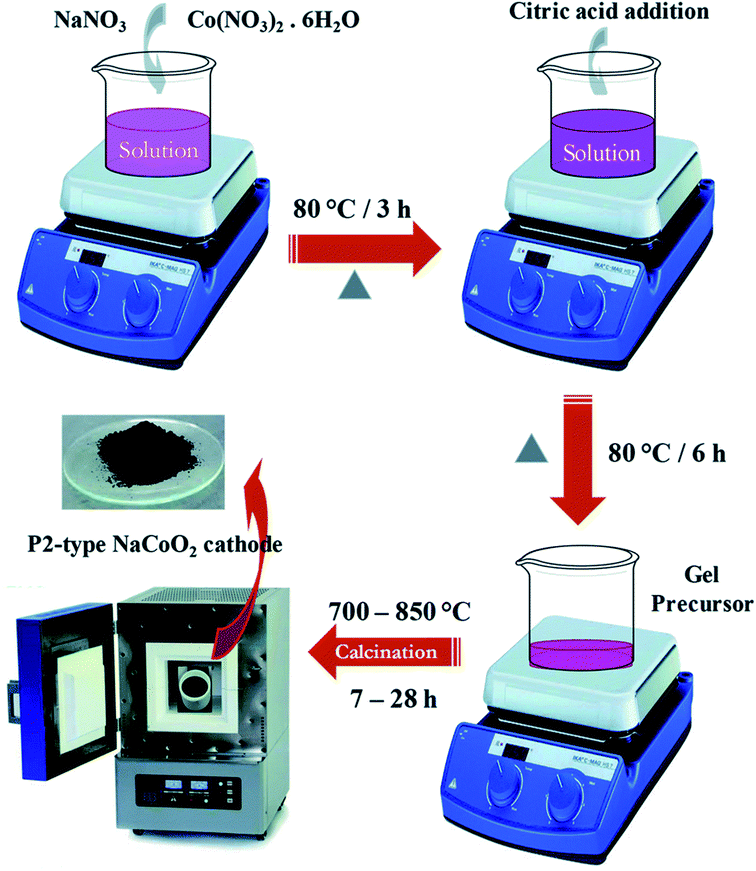 |
| | Fig. 23 Synthesis scheme of the NaCoO2 cathode. (Adapted from ref. 163, copyright 2021 Royal Society of Chemistry). | |
5. Current challenges and future directions
The important challenges for the TMO are the structural instability (caused by humidity sensitivity), irreversible phase transitions, and electrochemical degradations. And volume transformation during the redox reaction. This holds up the use of TMOs. By using in situ XRD, one can see that P2-type materials often go through a P2–O2 phase transition while O3-type materials go through a more complicated phase transition. The occurrence of this irreversible phase shift will cause the cathode material's structural degradation and capacity loss. Additionally, because the laminate materials are so sensitive to their surroundings, moisture and airborne CO2 will have some effect on them. The materials' electrochemical characteristics will degrade as a result of side reactions with the electrolyte. The current and future challenges the SIBs faces are mainly related to the complexity of cathode materials which are relatively underperforming in comparison with LIBs in terms of energy density, capacity, power density and cyclability. The alternative way to find suitable element addition to NaCoO2 which is redox inactive however boost the efficiency of SIBs. Cobalt is another expensive and towards toxic side hence the best alternative to replace Co with Ni, Mn, and Ti to make stability and enhance the performance of the SIBs, many reports already noted about this. This will surely reduce the manufacturing cost. However, the phase controlling of P2 and O3 in this layered structure is challenging which directly affect the performance of the SIBs. Another challenges that the SIBs are comprising with the anode materials which affecting the performance. The hard carbon will be best option to enhance the performance however the suitable and economical technique to grow hard carbon should be developed.
5.1 Irreversible phase transformation
In general, during the electrochemical cycle, the O3 and P2 phases go through a number of phase transitions affecting multiple stacking arrangements of the oxygen layer.173 The P2 phase often transitions to the O2 phase throughout the charging and discharging process as a result of the sliding of TMO6 octahedral layers with the removal of Na+. These issues cause the crystal structure to significantly shrink and the space between the layers to decrease. In contrast, Na+ initially settles in the shared TMO6 octahedral position with the edges during the O3 phase. The Na+ in the prism's core becomes energy stable when the sodium ions are partially removed from the O3 phase. This is related to the development of vacancies, which is analogous to the P2 phase. The TMO2 sheet is then moved while maintaining the TM–O bond, creating a wide prism centre. As a result, the usual oxygen build-up shifts from “ABCABC” to “ABBCCA,” which is a P3 phase. For NaNi0.5Mn0.5O2, the P2 phase typically exhibits a P2–O2 phase transition that can be seen by in situ XRD, however the O3 phase frequently experiences a more complex phase transition as shown in Fig. 24a than the P2 structure,174,175 such as O3 → O′3 → P3–P3′′.176–180 Therefore, P2 structured oxides always exhibit strong cycle stability and rate capacity because of their good structural integrity and low diffusion barrier.181
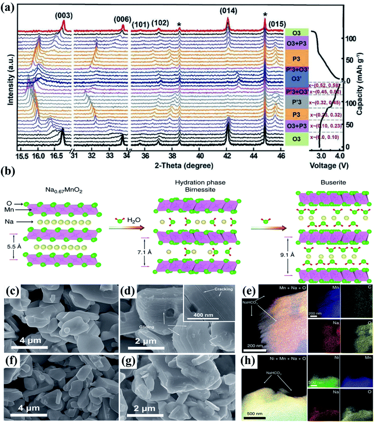 |
| | Fig. 24 (a) In situ XRD pattern of NaFe0.45Co0.5Mg0.05O2 (NaFCM) during the first cycle of charging and discharging at 2.0–4.5 V. (Adapted from ref. 174, copyright 2017 Wiley-VCH). (b) Influence of water absorption on the structure of the P2–Na0.67MnO2 material; the SEM images of (c) pristine and (d) relative humidity (RH) 93% + CO2 exposed Na0.67MnO2 powder, (e) the EDS mapping results of exposed Na0.67MnO2, indicating that NaHCO3 is formed on the particles' surface. SEM images of (f) pristine and (g) RH 93% + CO2 exposed Na0.67Ni0.33Mn0.67O2 powder, (h) the EDS mapping results of RH 93% + CO2 exposed Na0.67Ni0.33Mn0.67O2 samples, NaHCO3 particles are also observed on the surface of exposed Na0.67Ni0.33Mn0.67O2. (Adapted from ref. 182, copyright 2020, all rights reserved). | |
5.2 Structural instability due to humidity sensitivity
After being exposed to air, the layered cathode materials' hygroscopic qualities cause poor battery performance and higher transportation costs. Oxides with multilayer structures are extremely susceptible to environments with moisture. For instance, when its humid outside, water molecules will infiltrate the sodium layer, dramatically altering its structural makeup. CO2 will also have some effect on these materials because it can react with the oxides to produce electrochemically inert NaOH and Na2CO3. A thorough and organised understanding of the reaction mechanism of layered structure oxides in moist air is still lacking.183 As research objects in 2020, Zou et al.182 used Na0.67Ni0.33Mn0.67O2 and Na0.67MnO2 materials to examine structural evolution in a moisture environment as shown in Fig. 24(b). The chemical and structural changes that occur when materials are exposed to ambient air were carefully investigated using a variety of spectroscopy and electron microscopy characterization techniques, including in situ XRD, solid-state NMR, TOF-SIMS, and XRD as depicted in Fig. 24(c)–(h). This study is the first to suggest and demonstrate that the first cycle charging reaction potential can be utilised as the judging criteria for layered oxides' air stability, which will speed up the creation of high-performance cathodes for SIBs.
5.3 Electrochemical degradation
The layered oxide cathode experiences an irreversible phase change and water erosion, which causes rapid capacity decay and restricts the reversible capacity. Due to the following factors, the electrochemical performance of layered structure cathodes is still insufficient for large-scale device applications. First, the active components may be lost because of the transition metal ions dissolving into the electrolyte. The presence of Mn3+ in layered manganese-based cathode materials will cause the Mn–O bond to extend in a certain direction. Severe structural deformation results from the crystal structure's asymmetry. After Na+ is removed from the solid matrix, vacancies are created, creating areas for H2O/H insertion to create a protonated phase. The sodium ion diffusion coefficient may be significantly decreased because of this occurrence blocking ion transport routes. For instance, the capacity retention from the second cycle is as high as 87.7% for the P2-phase Na2/3Mn0.8Fe0.1Ti0.1O2 pristine electrode, whereas the moisture-exposed electrode only achieves 70% capacity retention.184–186
Researchers have been working diligently to find electrode materials with good performance to address the major challenges outlined before. Synthesis method, elemental doping, structural modulation, surface modification, and composite phase modulation are the key modification methodologies discussed here. Elemental doping is frequently employed to prevent irreversible phase changes during material cycling, surface coating can lessen electrolyte-particle side reactions, and the cathode material can be shielded from moisture and atmospheric CO2. In order to create satisfactory electrode materials, we can simultaneously design the structure and phase of the materials.
6. Techniques for improving the electrochemical performance of layered oxide materials
6.1 Synthesis methods to control and improve the morphology
The morphology and crystal structure of the layered oxide cathode material for SIBs influence the electrochemical performance of the battery. Thus, to preserve multiple phase formation, stable structure, low moisture sensitivity, high-level electronic conductivity, the changes of the structures is required. Generally, different synthesis methods for upgrading the crystal structure are developing to be a practical approach for lowering the sodium ion diffusion pathway and raising the surface area for Na+ ion intercalation/deintercalation. In general, the layered oxide cathode materials can be synthesized using the solid-state method. But the materials achieved by this method have not given good electrochemical performance. Therefore, the simple and most familiar synthesis process used is sol–gel method. The electrochemical performance is better as compared to other synthesis method, but this technique consumes most of the day which limits its useful applications. For making a small quantity of material and to obtain the ideal nanostructure, the hydrothermal method is also beneficial, however it does not give good electrochemical properties. Fu et al. synthesized Na0.44MnO2 nanorods with different solvents a raw material: sodium acetate (CH3COONa), acetic acid solution (CH3COOH), aqueous solution of manganous nitrate (Mn(NO3)2) by sol–gel method166 which show better electrochemical performance as compared to other methods. Every method has its own comparative advantages, has various conditions for cost and manufacture situation, as well as has some effects on the crystallinity, particle size, morphology, and phase purity of materials. Table 5 gives a concise difference of the merits and demerits of frequently used synthesis methods. Hence, to improve well layered TMO materials, the synthesis process requires to be constantly enhanced.187,188
Table 5 Merits and demerits of various synthetic processes for creating sodium ion-layered transition metal oxides
| Synthetic method |
Merits |
Demerits |
| Sol–gel method |
Low cost of production; good uniformity |
Reaction times are too slow, difficult to globalise |
| Solid-state method |
Simple operation, easy preparation |
Materials are not uniform, difficult to manage the morphology and particle size |
| Combustion method |
Fast and affordable synthesis method |
Poor control of combustion process and morphology |
| Coprecipitation |
Size and shape can be controlled more easily, and homogeneity is significantly higher |
High synthesis costs, restrictive synthesis requirements |
| Spray drying |
Fast drying times, easy management, and suitability for large-scale manufacture |
The requirements for spray dryer are high |
6.2 Doping
Doping of elements is one of the fundamental alteration strategies among the advancement studies on SIB cathode. Doping variation, also called replacement variation, is mainly to substitute portion of the equivalent site of the novel material structure by a minor number of additional ions or group structures and improving the performance and structure by creating vacancies, substantial voids, or change the lattice parameters. Corresponding to unique states of doping ions that can be divided into two ways: (1) cation doping and (2) anion doping. All has been showing effective for several cathodes in improving working voltage, enhancing rate capability, and increasing cycling stability.189
Generally, cation doping is commonly used to both oxide and polyanions, even though anion doping is generally found in polyanions. Additionally, doping of cations in a few cases is effective sufficient to achieve probable outcomes, although doping with only anions is observed to affect few side effects.190
Cation doping and anion doping. In TMOs, cation doping is mostly used to partially substitute sodium ions or other ion types with other metal cations. This strategy can accomplish numerous goals by picking the right replacement. To increase the cathode material's cycle performance, it first stabilizes the framework structure by preventing irreversible phase transitions.176Second, active doping increases operating voltage or improves specific capacity by inducing reversible oxygen redox activity or by introducing new transition metal-based redox processes, which enhances the cathode material's energy density.191 Additionally, a smoother pathway and a faster Na+ diffusion coefficient are provided by more Na+ vacancies by ions with a higher valence state (such as Ti4+), improving the rate performance of the cathode material. This is made possible by doping the Na site with larger ions or shortening the length of the TM–O bond.192,193
TMOs differ from polyanion cathode materials in the mechanism and outcome of anion doping. Some elements, whose radius is comparable to that of oxygen, such F, S, Cl, etc., are used to replace a minor quantity of O in TMOs. As a reference, Chen et al.194 suggested that F doping in Na0.6Mn0.95Ni0.05O2 can significantly enhance the activity of TM Ni2 by the creation of NiF bonds, increasing its working voltage and reversible specific capacity. Na0.6Mn0.95Ni0.05O1.95F0.05's formation of the Na–F bond between sodium and fluorine stabilised the structure, preventing it from collapsing after Na deintercalation. As a result, cycle stability was increased, and after 960 cycles at 2C, the capacity retention rate was 75.0 percent. Even at 50 °C, the rate performance of the F-doped Na0.6Mn0.95Ni0.05O2 samples is superior to that of the pristine samples, particularly Na0.6Mn0.95Ni0.05O1.95F0.05.
6.3 Surface coating
During the charging, discharging, and holding of a cell, it has been discovered that the surface of various cathodes materials would interact with electrolyte or air. An organic-inorganic mixed insulating layer, also known as the cathode-electrolyte interface (CEI), consisting primarily of Na2CO3, would develop from such a reaction on the cathode. Since it consumes a lot of Na, the electronic conductivity decreased, and the electrochemical property was compromised.195 Many researchers suggested applying coating modifications to the surface of cathode materials, such as carbon coating,196 polymer coating,197 and inorganic compound coating198 to solve these issues. The cathode material can avoid reacting with the air and electrolyte by having a coating layer on its surface that can stop Na from escaping. Also, to improve the cathode material's electronic conductivity and improve its electrochemical capabilities, the coating layer is preferably made of a conductive material with good electrical conductivity.199 In addition to monolayer coating, double-layer coating has also been reported, although not in SIB cathodes, hence it is not covered in detail here.
6.4 Structure design and morphology
Materials' morphology and structure are two important aspects that significantly affect their electrochemical characteristics. As a result, by carefully modifying the materials' internal structure and surface morphology, the electrochemical properties of cathode materials for SIBs can be maximized as summarized in Fig. 25.200 There are numerous studies on sodium TMOs that aim to increase the reaction area between electrolyte and electrode materials to speed up the transport of Na while maintaining a stable CEI. Strategies include creating porous architectures or manufacturing nanoscale electrode materials, both of which have helped sodium TMOs function more electrochemically.201
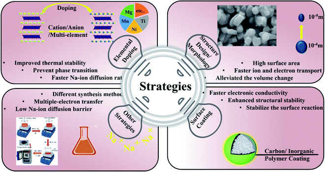 |
| | Fig. 25 Strategies of elemental doping, structure design/morphology, surface coating and other processes to enhance the SIB performance. | |
7. Conclusions
This review article provided the information about the development of LIB and SIB with drawback and advantages. It also deals with the complications exists with SIBs, including electrodes fabrication, assembling, economy factors. The cathode and anode material, synthesis, challenges, and alternatives are discussed in the review. The future prospects are also discussed, hopefully this review article will provide best insight of SIBs research community for the beginners and also for established researchers and industries too. In many battery technologies, layered O3|P2 cathode chemistry is at the leading position for the substantial improvement of the SIB performance over the past decades. The close structural similarities between layered lithium-ion cathodes and O3|P2 materials have assisted in modifying their commercial and scientific evolution. However, the higher complexity in the structure of O3|P2 materials, emerging from the capability of sodium ions to follow elongated octahedral and trigonal prismatic coordination, generates many difficulties and gives significant chances. The difficulties resulting from the combinational complexity of the permutation cations can also be possibilities to produce SIBs that can compete with the best LIBs. The opportunities are to develop SIBs that are reliable, economic, and competitive in performance with the best LIBs.
Author contribution
Archana Kanwade: conceptualization, formal analysis, writing-original draft. Sheetal Gupta: formal research, writing-original draft and editing. Akash Kankane: writing and correcting the draft; Subhash Chand Yadav: formal analysis, writing-original draft. Manish Kumar Tiwari: formal analysis, writing-original draft. Abhishek Srivastava: formal analysis, writing-original draft. Jena Akash Kumar Satrughna: formal analysis, writing-original draft. Parasharam M. Shirage: designing the review, conceptualization, formal analysis, funding acquisition, supervision, writing-review, corresponding and editing.
Conflicts of interest
There are no conflicts to declare.
Acknowledgements
AK, SG, JAKS, AS thankful to DST Inspire fellowships “IF200271, IF190547, IF190546, IF200232” for providing JRF fellowship for PhD. SCY thankful to CSIR for JRF and SRF fellowship “09/1022(0053)/2018 EMR-I”. Authors are thankful to the Prof. Suhas Joshi, Director SIC and Dept. of MEMS IIT Indore for providing research facility. PMS thankful to MSME, Govt of India through “Support for Entrepreneurial and Managerial Development of MSMEs through Incubators”, F. No. 3(10)/Inc/5th PAMC/2020-21 for starting incubation on “Sustainable, Engineered Sodium-ion Batteries for Renewable Energy Storage”.
References
- L. Sinha and P. M. Shirage, J. Electrochem. Soc., 2019, 166, A3496 CrossRef CAS.
- M. Palanisamy, V. R. R. Boddu, P. M. Shirage and V. G. Pol, ACS Appl. Mater. Interfaces, 2021, 13(27), 31594–31604 CrossRef CAS PubMed.
- V. R. R. Boddu, D. Puthusseri, P. M. Shirage, P. Mathur and V. G. Pol, Ionics, 2021, 27, 4549–4572 CrossRef CAS.
- S. C. Yadav, A. Sharma, R. S. Devan and P. M. Shirage, Opt. Mater., 2022, 124, 112066 CrossRef CAS.
- S. C. Yadav, A. Srivastava, V. Manjunath, A. Kanwade, R. S. Devan and P. M. Shirage, Mater. Today Phys., 2022, 100731 CrossRef.
- Y. Zhao, Y. Ding, Y. Li, L. Peng, H. R. Byon, J. B. Goodenough and G. Yu, Chem. Soc. Rev., 2015, 44, 7968–7996 RSC.
- M. Winter and R. J. Brodd, Chem. Rev., 2004, 104, 4245–4270 CrossRef CAS PubMed.
- A. Das, D. Li, D. Williams and D. Greenwood, World Electric Vehicle Journal, 2018, 9, 22 CrossRef.
- H. Lichchhavi Lee, Y. Ohshita, A. K. Singh and P. M. Shirage, Langmuir, 2021, 37(3), 1141–1151 CrossRef PubMed.
- M. Verma, L. Sinha and P. M. Shirage, J. Mater. Sci.: Mater. Electron., 2021, 32, 12292–12307 CrossRef CAS.
- C. Costa, J. G. Ribelles, S. Lanceros-Méndez, G. Appetecchi and B. Scrosati, J. Power Sources, 2014, 245, 779–786 CrossRef CAS.
- A. Manthiram, X. Yu and S. Wang, Nat. Rev. Mater., 2017, 2, 1–16 Search PubMed.
- D. D. Potphode, L. Sinha and P. M. Shirage, Appl. Surf. Sci., 2019, 469, 162–172 CrossRef CAS.
- W. Zhang, Z. Tu, J. Qian, S. Choudhury, L. A. Archer and Y. Lu, Small, 2018, 14, 1703001 CrossRef PubMed.
- X. Luo, J. Wang, M. Dooner and J. Clarke, Appl. Energy, 2015, 137, 511–536 CrossRef.
- J.-S. Zheng, L. Zhang, A. Shellikeri, W. Cao, Q. Wu and J. P. Zheng, Sci. Rep., 2017, 7, 1–8 CrossRef PubMed.
- C. Vaalma, D. Buchholz, M. Weil and S. Passerini, Nat. Rev. Mater., 2018, 3, 1–11 CrossRef.
- P. K. Nayak, L. Yang, W. Brehm and P. Adelhelm, Angew. Chem., Int. Ed., 2018, 57, 102–120 CrossRef CAS PubMed.
- Y. Nishi, Chem. Rec., 2001, 1, 406–413 CrossRef CAS PubMed.
- M. D. Slater, D. Kim, E. Lee and C. S. Johnson, Adv. Funct. Mater., 2013, 23, 947–958 CrossRef CAS.
- Y. Kim, K. H. Ha, S. M. Oh and K. T. Lee, Chem.–Eur. J., 2014, 20, 11980–11992 CrossRef CAS PubMed.
- K. Abraham, Solid State Ionics, 1982, 7, 199–212 CrossRef CAS.
- A. Yoshino, Angew. Chem., Int. Ed., 2012, 51, 5798–5800 CrossRef CAS PubMed.
- J. Xiao, X. Li, K. Tang, D. Wang, M. Long, H. Gao, W. Chen, C. Liu, H. Liu and G. Wang, Mater. Chem. Front., 2021, 5, 3735–3764 RSC.
- Lichchhavi, H. Lee, Y. Ohshita, A. K. Singh and P. M. Shirage, Langmuir, 2021, 37, 1141–1151 CrossRef CAS PubMed.
- M. M. Thackeray, S.-H. Kang, C. S. Johnson, J. T. Vaughey, R. Benedek and S. Hackney, J. Mater. Chem., 2007, 17, 3112–3125 RSC.
- W. J. Li, C. Han, W. Wang, F. Gebert, S. L. Chou, H. K. Liu, X. Zhang and S. X. Dou, Adv. Energy Mater., 2017, 7, 1700274 CrossRef.
- Q. Liu, Z. Hu, M. Chen, C. Zou, H. Jin, S. Wang, S. L. Chou, Y. Liu and S. X. Dou, Adv. Funct. Mater., 2020, 30, 1909530 CrossRef CAS.
- P. Bhojane, L. Sinha, U. K. Goutam and P. M. Shirage, Electrochim. Acta, 2019, 296, 112–119 CrossRef CAS.
- C. Delmas, C. Fouassier and P. Hagenmuller, Physica B+C, 1980, 99, 81–85 CrossRef CAS.
- N. Yabuuchi, K. Kubota, M. Dahbi and S. Komaba, Chem. Rev., 2014, 114, 11636–11682 CrossRef CAS PubMed.
- H. Pan, Y.-S. Hu and L. Chen, Energy Environ. Sci., 2013, 6, 2338–2360 RSC.
- Q. Zhang, E. Uchaker, S. L. Candelaria and G. Cao, Chem. Soc. Rev., 2013, 42, 3127–3171 RSC.
- M. Á. Muñoz-Márquez, D. Saurel, J. L. Gómez-Cámer, M. Casas-Cabanas, E. Castillo-Martínez and T. Rojo, Adv. Energy Mater., 2017, 7, 1700463 CrossRef.
- M. Brand, S. Gläser, J. Geder, S. Menacher, S. Obpacher, A. Jossen and D. Quinger, World Electric Vehicle Journal, 2013, 6, 572–580 CrossRef.
- R. Dell and D. A. J. Rand, Understanding batteries, Royal Society of Chemistry, 2001 Search PubMed.
- P. Kurzweil, J. Power Sources, 2010, 195, 4424–4434 CrossRef CAS.
- S. S. Zhang, J. Power Sources, 2007, 164, 351–364 CrossRef CAS.
- J.-L. Shi, L.-F. Fang, H. Li, H. Zhang, B.-K. Zhu and L.-P. Zhu, J. Membr. Sci., 2013, 437, 160–168 CrossRef CAS.
- X. Song, X. Li, Z. Bai, B. Yan, D. Li and X. Sun, Nano Energy, 2016, 26, 533–540 CrossRef CAS.
- X. Liu, Y. Wang, Z. Wang, T. Zhou, M. Yu, L. Xiu and J. Qiu, J. Mater. Chem. A, 2017, 5, 10398–10405 RSC.
- S. Wang, L. Xia, L. Yu, L. Zhang, H. Wang and X. W. Lou, Adv. Energy Mater., 2016, 6, 1502217 CrossRef.
- M. Palanisamy, V. R. Reddy Boddu, P. M. Shirage and V. G. Pol, ACS Appl. Mater. Interfaces, 2021, 13, 31594–31604 CrossRef CAS PubMed.
- A. Kanwade, S. Gupta, A. Kankane, A. Srivastava, S. C. Yadav and P. M. Shirage, Sustainable Energy Fuels, 2022, 6, 3114–3147 RSC.
- Y. You, X.-L. Wu, Y.-X. Yin and Y.-G. Guo, Energy Environ. Sci., 2014, 7, 1643–1647 RSC.
- C. Masquelier and L. Croguennec, Chem. Rev., 2013, 113, 6552–6591 CrossRef CAS PubMed.
- A. K. Rana, Y. Kumar, P. Rajput, S. N. Jha, D. Bhattacharyya and P. M. Shirage, ACS Appl. Mater. Interfaces, 2017, 9, 7691–7700 CrossRef CAS PubMed.
- Y. Kumar and P. M. Shirage, J. Mater. Sci., 2017, 52, 4840–4851 CrossRef CAS.
- J. Jin, Y. Liu, X. Pang, Y. Wang, X. Xing and J. Chen, Sci. China: Chem., 2021, 64, 385–402 CrossRef CAS.
- C. Wang, L. Liu, S. Zhao, Y. Liu, Y. Yang, H. Yu, S. Lee, G.-H. Lee, Y.-M. Kang and R. Liu, Nat. Commun., 2021, 12, 1–9 CrossRef PubMed.
- J. Liu, W. H. Kan and C. D. Ling, J. Power Sources, 2021, 481, 229139 CrossRef CAS.
- Y. Yu, D. Ning, Q. Li, A. Franz, L. Zheng, N. Zhang, G. Ren, G. Schumacher and X. Liu, Energy Storage Mater., 2021, 38, 130–140 CrossRef.
- T. Song and E. Kendrick, J. Phys.: Mater., 2021, 4, 032004 CAS.
- R. J. Clément, P. G. Bruce and C. P. Grey, J. Electrochem. Soc., 2015, 162, A2589 CrossRef.
- A. Sharma, P. Bhojane, A. K. Rana, Y. Kumar and P. M. Shirage, Scr. Mater., 2017, 128, 65–68 CrossRef CAS.
- K. Kubota, N. Yabuuchi, H. Yoshida, M. Dahbi and S. Komaba, MRS Bull., 2014, 39, 416–422 CrossRef CAS.
- S. Mariyappan, Q. Wang and J. M. Tarascon, J. Electrochem. Soc., 2018, 165, A3714 CrossRef CAS.
- K. Kubota, M. Dahbi, T. Hosaka, S. Kumakura and S. Komaba, Chem. Rec., 2018, 18, 459–479 CrossRef CAS PubMed.
- K. Kubota, N. Fujitani, Y. Yoda, K. Kuroki, Y. Tokita and S. Komaba, J. Mater. Chem. A, 2021, 9, 12830–12844 RSC.
- J. Wang, Z. Zhou, Y. Li, M. Li, F. Wang, Q. Yao, Z. Wang, H. Zhou and J. Deng, J. Alloys Compd., 2019, 792, 1054–1060 CrossRef CAS.
- P. Bhojane, S. Sen and P. M. Shirage, Appl. Surf. Sci., 2016, 377, 376–384 CrossRef CAS.
- H.-R. Yao, P.-F. Wang, Y. Gong, J. Zhang, X. Yu, L. Gu, C. OuYang, Y.-X. Yin, E. Hu and X.-Q. Yang, J. Am. Chem. Soc., 2017, 139, 8440–8443 CrossRef CAS PubMed.
- Q. Wang, S. Mariyappan, J. Vergnet, A. M. Abakumov, G. Rousse, F. Rabuel, M. Chakir and J. M. Tarascon, Adv. Energy Mater., 2019, 9, 1901785 CrossRef.
- S. Mariyappan, T. Marchandier, F. Rabuel, A. Iadecola, G. Rousse, A. V. Morozov, A. M. Abakumov and J.-M. Tarascon, Chem. Mater., 2020, 32, 1657–1666 CrossRef CAS.
- J.-Y. Hwang, T.-Y. Yu and Y.-K. Sun, J. Mater. Chem. A, 2018, 6, 16854–16862 RSC.
- Y. Wang, Z. Feng, P. Cui, W. Zhu, Y. Gong, M.-A. Girard, G. Lajoie, J. Trottier, Q. Zhang and L. Gu, Nat. Commun., 2021, 12, 1–11 CrossRef PubMed.
- J.-Y. Hwang, S.-T. Myung and Y.-K. Sun, J. Phys. Chem. C, 2018, 122, 13500–13507 CrossRef CAS.
- M. Leng, J. Bi, W. Wang, Z. Xing, W. Yan, X. Gao, J. Wang and R. Liu, J. Alloys Compd., 2020, 816, 152581 CrossRef CAS.
- I. Lee, G. Oh, S. Lee, T.-Y. Yu, M. H. Alfaruqi, V. Mathew, B. Sambandam, Y.-K. Sun, J.-Y. Hwang and J. Kim, Energy Storage Mater., 2021, 41, 183–195 CrossRef.
- X. Meng, D. Zhang, Z. Zhao, Y. Li, S. Xu, L. Chen, X. Wang, S. Liu and Y. Wu, J. Alloys Compd., 2021, 887, 161366 CrossRef CAS.
- J. Lamb, K. Jarvis and A. Manthiram, Small, 2022, 2106927 CrossRef PubMed.
- L. A. Ma, R. Palm, E. Nocerino, O. Kenji, N. Matsubara, S. Cottrell, K. Yokoyama, A. Koda, J. Sugiyama and Y. Sassa, Phys. Chem. Chem. Phys., 2021, 23, 24478 RSC.
- S. Guo, Y. Sun, J. Yi, K. Zhu, P. Liu, Y. Zhu, G.-z. Zhu, M. Chen, M. Ishida and H. Zhou, NPG Asia Mater., 2016, 8, e266 CrossRef CAS.
- N. Tapia-Ruiz, A. R. Armstrong, H. Alptekin, M. A. Amores, H. Au, J. Barker, R. Boston, W. R. Brant, J. M. Brittain and Y. Chen, J. Phys.: Energy, 2021, 3, 031503 CAS.
- Z.-Y. Li, R. Gao, J. Zhang, X. Zhang, Z. Hu and X. Liu, J. Mater. Chem. A, 2016, 4, 3453–3461 RSC.
- D. H. Lee, J. Xu and Y. S. Meng, Phys. Chem. Chem. Phys., 2013, 15, 3304–3312 RSC.
- B. Li and D. Xia, Adv. Mater., 2017, 29, 1701054 CrossRef PubMed.
- C. Yin, L. Wan, B. Qiu, F. Wang, W. Jiang, H. Cui, J. Bai, S. Ehrlich, Z. Wei and Z. Liu, Energy Storage Mater., 2021, 35, 388–399 CrossRef.
- Y. Yu, P. Karayaylali, S. H. Nowak, L. Giordano, M. Gauthier, W. Hong, R. Kou, Q. Li, J. Vinson and T. Kroll, Chem. Mater., 2019, 31, 7864–7876 CrossRef CAS PubMed.
- C. Ma, J. Alvarado, J. Xu, R. l. J. Clément, M. Kodur, W. Tong, C. P. Grey and Y. S. Meng, J. Am. Chem. Soc., 2017, 139, 4835–4845 CrossRef CAS PubMed.
- C. Hakim, N. Sabi, L. A. Ma, M. Dahbi, D. Brandell, K. Edström, L. C. Duda, I. Saadoune and R. Younesi, Commun. Chem., 2020, 3, 1–9 CrossRef.
- G. Singh, N. Tapia-Ruiz, J. M. Lopez del Amo, U. Maitra, J. W. Somerville, A. R. Armstrong, J. Martinez de Ilarduya, T. Rojo and P. G. Bruce, Chem. Mater., 2016, 28, 5087–5094 CrossRef.
- S. Doubaji, M. Valvo, I. Saadoune, M. Dahbi and K. Edström, J. Power Sources, 2014, 266, 275–281 CrossRef CAS.
- L. Yang, X. Li, J. Liu, S. Xiong, X. Ma, P. Liu, J. Bai, W. Xu, Y. Tang and Y.-Y. Hu, J. Am. Chem. Soc., 2019, 141, 6680–6689 CrossRef CAS PubMed.
- Y. Xie, E. Gabriel, L. Fan, I. Hwang, X. Li, H. Zhu, Y. Ren, C. Sun, J. Pipkin and M. Dustin, Chem. Mater., 2021, 33, 4445–4455 CrossRef CAS PubMed.
- T. Jin, P. F. Wang, Q. C. Wang, K. Zhu, T. Deng, J. Zhang, W. Zhang, X. Q. Yang, L. Jiao and C. Wang, Angew. Chem., 2020, 132, 14619–14624 CrossRef.
- Z. Liu, J. Shen, S. Feng, Y. Huang, D. Wu, F. Li, Y. Zhu, M. Gu, Q. Liu and J. Liu, Angew. Chem., 2021, 133, 21128–21137 CrossRef.
- C. Li, A. Li, M. Li, P. Xiong, Y. Liu, M. Cheng, D. Geng and Y. Xu, ACS Appl. Mater. Interfaces, 2022, 14(21), 24462–24468 CrossRef CAS PubMed.
- Z. Cheng, B. Zhao, Y. J. Guo, L. Yu, B. Yuan, W. Hua, Y. X. Yin, S. Xu, B. Xiao and X. Han, Adv. Energy Mater., 2022, 12, 2103461 CrossRef CAS.
- K. Wang, Z.-G. Wu, G. Melinte, Z.-G. Yang, A. Sarkar, W. Hua, X. Mu, Z.-W. Yin, J.-T. Li and X.-D. Guo, J. Mater. Chem. A, 2021, 9, 13151–13160 RSC.
- Q. Liu, Z. Hu, M. Chen, C. Zou, H. Jin, S. Wang, S.-L. Chou, Y. Liu and S.-X. Dou, Adv. Funct. Mater., 2020, 30, 1909530 CrossRef CAS.
- R. Berthelot, D. Carlier and C. Delmas, Nat. Mater., 2011, 10, 74–80 CrossRef CAS PubMed.
- Y. Biecher, A. Baux, F. o. Fauth, C. Delmas, G. R. Goward and D. Carlier, Chem. Mater., 2022, 34(14), 6431–6439 CrossRef CAS.
- R. Zhang, Z. Lu, Y. Yang and W. Shi, Curr. Appl. Phys., 2018, 18, 1431–1435 CrossRef.
- N. Sabi, A. Sarapulova, S. Indris, S. Dsoke, Z. Zhao, M. Dahbi, H. Ehrenberg and I. Saadoune, ChemElectroChem, 2019, 6, 892–903 CrossRef CAS.
- M. O. N. M. M. VN and Y. H. M. Dall'Agnese, Nat. Commun., 2013, 4, 1716 CrossRef PubMed.
- Z. Fu, N. Wang, D. Legut, C. Si, Q. Zhang, S. Du, T. C. Germann, J. S. Francisco and R. Zhang, Chem. Rev., 2019, 119, 11980–12031 CrossRef CAS PubMed.
- W. Zhang, X. Sun, Y. Tang, H. Xia, Y. Zeng, L. Qiao, Z. Zhu, Z. Lv, Y. Zhang and X. Ge, J. Am. Chem. Soc., 2019, 141, 14038–14042 CrossRef CAS PubMed.
- M. Ye, C. Chen, N. Zhang, X. Wen, W. Guo and C. Lin, Adv. Energy Mater., 2014, 4, 1301564 CrossRef.
- Q. Li, S. Guo, K. Zhu, K. Jiang, X. Zhang, P. He and H. Zhou, Adv. Energy Mater., 2017, 7, 1700361 CrossRef.
- X. He, J. Wang, B. Qiu, E. Paillard, C. Ma, X. Cao, H. Liu, M. C. Stan, H. Liu and T. Gallash, Nano Energy, 2016, 27, 602–610 CrossRef CAS.
- N. Tolganbek, Y. Yerkinbekova, S. Kalybekkyzy, Z. Bakenov and A. Mentbayeva, J. Alloys Compd., 2021, 882, 160774 CrossRef CAS.
- I. Quinzeni, K. Fujii, M. Bini, M. Yashima and C. Tealdi, Mater. Adv., 2022, 3, 986–997 RSC.
- X. Cai, Y. Xu, L. Meng, X. Wei, F. Xiong, T. Xiong and Q. An, J. Alloys Compd., 2020, 820, 153093 CrossRef CAS.
- R. Li, Y. Liu, Z. Wang and J. Li, Electrochim. Acta, 2019, 318, 14–22 CrossRef CAS.
- R.-M. Gao, Z.-J. Zheng, P.-F. Wang, C.-Y. Wang, H. Ye and F.-F. Cao, Energy Storage Mater., 2020, 30, 9–26 CrossRef.
- E. De La Llave, E. Talaie, E. Levi, P. K. Nayak, M. Dixit, P. T. Rao, P. Hartmann, F. Chesneau, D. T. Major and M. Greenstein, Chem. Mater., 2016, 28, 9064–9076 CrossRef CAS.
- L. G. Chagas, D. Buchholz, L. Wu, B. Vortmann and S. Passerini, J. Power Sources, 2014, 247, 377–383 CrossRef CAS.
- J. Y. Hwang, J. Kim, T. Y. Yu and Y. K. Sun, Adv. Energy Mater., 2019, 9, 1803346 CrossRef.
- Y. Wen, J. Fan, C. Shi, P. Dai, Y. Hong, R. Wang, L. Wu, Z. Zhou, J. Li and L. Huang, Nano Energy, 2019, 60, 162–170 CrossRef CAS.
- Y. Xiao, Y. F. Zhu, H. R. Yao, P. F. Wang, X. D. Zhang, H. Li, X. Yang, L. Gu, Y. C. Li and T. Wang, Adv. Energy Mater., 2019, 9, 1803978 CrossRef.
- S.-M. Oh, S.-T. Myung, J.-Y. Hwang, B. Scrosati, K. Amine and Y.-K. Sun, Chem. Mater., 2014, 26, 6165–6171 CrossRef CAS.
- L. Sun, Y. Xie, X. Z. Liao, H. Wang, G. Tan, Z. Chen, Y. Ren, J. Gim, W. Tang and Y. S. He, Small, 2018, 14, 1704523 CrossRef PubMed.
- J. Yang, M. Tang, H. Liu, X. Chen, Z. Xu, J. Huang, Q. Su and Y. Xia, Small, 2019, 15, 1905311 CrossRef CAS PubMed.
- J. Xu, Z. Han, K. Jiang, P. Bai, Y. Liang, X. Zhang, P. Wang, S. Guo and H. Zhou, Small, 2020, 16, 1904388 CrossRef CAS PubMed.
- D. Zhou, W. Huang, X. Lv and F. Zhao, J. Power Sources, 2019, 421, 147–155 CrossRef CAS.
- M. Bianchini, E. Gonzalo, N. E. Drewett, N. Ortiz-Vitoriano, J. M. L. del Amo, F. J. Bonilla, B. Acebedo and T. Rojo, J. Mater. Chem. A, 2018, 6, 3552–3559 RSC.
- Y.-N. Zhou, P.-F. Wang, Y.-B. Niu, Q. Li, X. Yu, Y.-X. Yin, S. Xu and Y.-G. Guo, Nano Energy, 2019, 55, 143–150 CrossRef CAS.
- X. Chen, X. Zhou, M. Hu, J. Liang, D. Wu, J. Wei and Z. Zhou, J. Mater. Chem. A, 2015, 3, 20708–20714 RSC.
- D. Wang, H. Chen, X. Zheng, L. Qiu, J. Qu, Z. Wu, Y. Zhong, W. Xiang, B. Zhong and X. Guo, ChemElectroChem, 2019, 6, 5155–5161 CrossRef CAS.
- K. Kaliyappan, T. Or, Y. P. Deng, Y. Hu, Z. Bai and Z. Chen, Adv. Funct. Mater., 2020, 30, 1910251 CrossRef CAS.
- X. Zhang, S. Guo, P. Liu, Q. Li, S. Xu, Y. Liu, K. Jiang, P. He, M. Chen and P. Wang, Adv. Energy Mater., 2019, 9, 1900189 CrossRef.
- J. U. Choi, Y. J. Park, J. H. Jo, L.-Y. Kuo, P. Kaghazchi and S.-T. Myung, ACS Appl. Mater. Interfaces, 2018, 10, 40978–40984 CrossRef CAS PubMed.
- P. F. Wang, H. R. Yao, X. Y. Liu, J. N. Zhang, L. Gu, X. Q. Yu, Y. X. Yin and Y. G. Guo, Adv. Mater., 2017, 29, 1700210 CrossRef PubMed.
- M. H. Han, E. Gonzalo, N. Sharma, J. M. López del Amo, M. Armand, M. Avdeev, J. J. Saiz Garitaonandia and T. Rojo, Chem. Mater., 2016, 28, 106–116 CrossRef CAS.
- W. Zheng, Q. Liu, Z. Wang, Z. Wu, S. Gu, L. Cao, K. Zhang, J. Fransaer and Z. Lu, Energy Storage Mater., 2020, 28, 300–306 CrossRef.
- X. Zhang, Y. Qiao, S. Guo, K. Jiang, S. Xu, H. Xu, P. Wang, P. He and H. Zhou, Adv. Mater., 2019, 31, 1807770 CrossRef PubMed.
- X. Liu, W. Zuo, B. Zheng, Y. Xiang, K. Zhou, Z. Xiao, P. Shan, J. Shi, Q. Li and G. Zhong, Angew. Chem., Int. Ed., 2019, 58, 18086–18095 CrossRef CAS PubMed.
- A. Konarov, J. U. Choi, Z. Bakenov and S.-T. Myung, J. Mater. Chem. A, 2018, 6, 8558–8567 RSC.
- I. Hasa, S. Passerini and J. Hassoun, J. Mater. Chem. A, 2017, 5, 4467–4477 RSC.
- H. Wang, X.-Z. Liao, Y. Yang, X. Yan, Y.-S. He and Z.-F. Ma, J. Electrochem. Soc., 2016, 163, A565 CrossRef CAS.
- Y. Shi, S. Li, A. Gao, J. Zheng, Q. Zhang, X. Lu, L. Gu and D. Cao, ACS Appl. Mater. Interfaces, 2019, 11, 24122–24131 CrossRef CAS PubMed.
- C. Luo, A. Langrock, X. Fan, Y. Liang and C. Wang, J. Mater. Chem. A, 2017, 5, 18214–18220 RSC.
- P. Vassilaras, X. Ma, X. Li and G. Ceder, J. Electrochem. Soc., 2012, 160, A207 CrossRef.
- J. U. Choi, J. H. Jo, Y. J. Park, K. S. Lee and S. T. Myung, Adv. Energy Mater., 2020, 10, 2001346 CrossRef CAS.
- Y. Shao, Z.-f. Tang, J.-y. Liao and C.-h. Chen, Chin. J. Chem. Phys., 2018, 31, 673–676 CrossRef CAS.
- T. Fang, S. Guo, K. Jiang, X. Zhang, D. Wang, Y. Feng, X. Zhang, P. Wang, P. He and H. Zhou, Small Methods, 2019, 3, 1800183 CrossRef CAS.
- B. M. De Boisse, J.-H. Cheng, D. Carlier, M. Guignard, C.-J. Pan, S. Bordere, D. Filimonov, C. Drathen, E. Suard and B.-J. Hwang, J. Mater. Chem. A, 2015, 3, 10976–10989 RSC.
- J. Xiao, F. Zhang, K. Tang, X. Li, D. Wang, Y. Wang, H. Liu, M. Wu and G. Wang, ACS Cent. Sci., 2019, 5, 1937–1945 CrossRef CAS PubMed.
- A. Tripathi, A. Rudola, S. R. Gajjela, S. Xi and P. Balaya, J. Mater. Chem. A, 2019, 7, 25944–25960 RSC.
- K. Jiang, X. Zhang, H. Li, X. Zhang, P. He, S. Guo and H. Zhou, ACS Appl. Mater. Interfaces, 2019, 11, 14848–14853 CrossRef CAS PubMed.
- L. Mu, S. Xu, Y. Li, Y. S. Hu, H. Li, L. Chen and X. Huang, Adv. Mater., 2015, 27, 6928–6933 CrossRef CAS PubMed.
- A. Konarov, H. J. Kim, N. Voronina, Z. Bakenov and S.-T. Myung, ACS Appl. Mater. Interfaces, 2019, 11, 28928–28933 CrossRef CAS PubMed.
- M. Linqin, Q. Xinguo, H. Yongsheng, L. Hong, C. Liquan and H. Xuejie, Energy Storage Sci. Technol., 2016, 5, 324 Search PubMed.
- Y. Wang, G. Hu, Z. Peng, Y. Cao, X. Lai, X. Qi, Z. Gan, W. Li, Z. Luo and K. Du, J. Power Sources, 2018, 396, 639–647 CrossRef CAS.
- M.-H. Cao, Z. Shadike, Y.-N. Zhou and Z.-W. Fu, Electrochim.
Acta, 2019, 295, 918–925 CrossRef CAS.
- Q. C. Wang, E. Hu, Y. Pan, N. Xiao, F. Hong, Z. W. Fu, X. J. Wu, S. M. Bak, X. Q. Yang and Y. N. Zhou, Adv. Sci., 2017, 4, 1700219 CrossRef PubMed.
- M.-H. Cao, Y. Wang, Z. Shadike, J.-L. Yue, E. Hu, S.-M. Bak, Y.-N. Zhou, X.-Q. Yang and Z.-W. Fu, J. Mater. Chem. A, 2017, 5, 5442–5448 RSC.
- C. Zhang, R. Gao, L. Zheng, Y. Hao and X. Liu, ACS Appl. Mater. Interfaces, 2018, 10, 10819–10827 CrossRef CAS PubMed.
- K. Kaliyappan, W. Xaio, T. K. Sham and X. Sun, Adv. Funct. Mater., 2018, 28, 1801898 CrossRef.
- J.-L. Yue, Y.-N. Zhou, X. Yu, S.-M. Bak, X.-Q. Yang and Z.-W. Fu, J. Mater. Chem. A, 2015, 3, 23261–23267 RSC.
- J. Zhang, W. Wang, W. Wang, S. Wang and B. Li, ACS Appl. Mater. Interfaces, 2019, 11, 22051–22066 CrossRef CAS PubMed.
- J. E. Wang, W. H. Han, K. J. Chang, Y. H. Jung and D. K. Kim, J. Mater. Chem. A, 2018, 6, 22731–22740 RSC.
- K. Wang, H. Wan, P. Yan, X. Chen, J. Fu, Z. Liu, H. Deng, F. Gao and M. Sui, Adv. Mater., 2019, 31, 1904816 CrossRef CAS PubMed.
- J. Deng, W. B. Luo, X. Lu, Q. Yao, Z. Wang, H. K. Liu, H. Zhou and S. X. Dou, Adv. Energy Mater., 2018, 8, 1701610 CrossRef.
- X.-H. Zhang, W.-L. Pang, F. Wan, J.-Z. Guo, H.-Y. Lü, J.-Y. Li, Y.-M. Xing, J.-P. Zhang and X.-L. Wu, ACS Appl. Mater. Interfaces, 2016, 8, 20650–20659 CrossRef CAS PubMed.
- Y. Liu, Q. Shen, X. Zhao, J. Zhang, X. Liu, T. Wang, N. Zhang, L. Jiao, J. Chen and L. Z. Fan, Adv. Funct. Mater., 2020, 30, 1907837 CrossRef CAS.
- Y. You, S. Xin, H. Y. Asl, W. Li, P.-F. Wang, Y.-G. Guo and A. Manthiram, Chem, 2018, 4, 2124–2139 CAS.
- C. Li, C. Zhao, B. Hu, W. Tong, M. Shen and B. Hu, Chem. Mater., 2020, 32, 1054–1063 CrossRef CAS.
- L. Zhang, T. Yuan, L. Soule, H. Sun, Y. Pang, J. Yang and S. Zheng, ACS Appl. Energy Mater., 2020, 3, 3770–3778 CrossRef CAS.
- S. Zheng, G. Zhong, M. J. McDonald, Z. Gong, R. Liu, W. Wen, C. Yang and Y. Yang, J. Mater. Chem. A, 2016, 4, 9054–9062 RSC.
- P.-F. Wang, Y. You, Y.-X. Yin and Y.-G. Guo, J. Mater. Chem. A, 2016, 4, 17660–17664 RSC.
- V. R. R. Boddu, M. Palanisamy, L. Sinha, S. C. Yadav, V. G. Pol and P. M. Shirage, Sustainable Energy Fuels, 2021, 5, 3219–3228 RSC.
- V. Dall'Asta, D. Buchholz, L. G. Chagas, X. Dou, C. Ferrara, E. Quartarone, C. Tealdi and S. Passerini, ACS Appl. Mater. Interfaces, 2017, 9, 34891–34899 CrossRef PubMed.
- Q. Liu, Z. Hu, M. Chen, Q. Gu, Y. Dou, Z. Sun, S. Chou and S. X. Dou, ACS Appl. Mater. Interfaces, 2017, 9, 3644–3652 CrossRef CAS PubMed.
- B. Fu, Y. Su, J. Yu, S. Xie and J. Li, Electrochim. Acta, 2019, 303, 125–132 CrossRef CAS.
- K. Dai, J. Mao, X. Song, V. Battaglia and G. Liu, J. Power Sources, 2015, 285, 161–168 CrossRef CAS.
- B. Fu, X. Zhou and Y. Wang, J. Power Sources, 2016, 310, 102–108 CrossRef CAS.
- E. Hosono, T. Saito, J. Hoshino, M. Okubo, Y. Saito, D. Nishio-Hamane, T. Kudo and H. Zhou, J. Power Sources, 2012, 217, 43–46 CrossRef CAS.
- N. Sheng, C.-g. Han, Y. Lei and C. Zhu, Electrochim. Acta, 2018, 283, 1560–1567 CrossRef CAS.
- D. Zhang, W.-j. Shi, Y.-w. Yan, S.-d. Xu, L. Chen, X.-m. Wang and S.-b. Liu, Electrochim. Acta, 2017, 258, 1035–1043 CrossRef CAS.
- R. Qiao, K. Dai, J. Mao, T.-C. Weng, D. Sokaras, D. Nordlund, X. Song, V. S. Battaglia, Z. Hussain and G. Liu, Nano Energy, 2015, 16, 186–195 CrossRef CAS.
- D. Pahari and S. Puravankara, J. Power Sources, 2020, 455, 227957 CrossRef CAS.
- H. R. Yao, P. F. Wang, Y. Wang, X. Yu, Y. X. Yin and Y. G. Guo, Adv. Energy Mater., 2017, 7, 1700189 CrossRef.
- L. Wang, J. Wang, X. Zhang, Y. Ren, P. Zuo, G. Yin and J. Wang, Nano Energy, 2017, 34, 215–223 CrossRef CAS.
- Y. Wang, L. Wang, H. Zhu, J. Chu, Y. Fang, L. Wu, L. Huang, Y. Ren, C. J. Sun and Q. Liu, Adv. Funct. Mater., 2020, 30, 1910327 CrossRef CAS.
- S. Komaba, N. Yabuuchi, T. Nakayama, A. Ogata, T. Ishikawa and I. Nakai, Inorg. Chem., 2012, 51, 6211–6220 CrossRef CAS PubMed.
- K. Wang, P. Yan and M. Sui, Nano Energy, 2018, 54, 148–155 CrossRef CAS.
- L. Wang, J. Wang, F. Guo, L. Ma, Y. Ren, T. Wu, P. Zuo, G. Yin and J. Wang, Nano Energy, 2018, 43, 184–191 CrossRef CAS.
- Q. Liu, Z. Hu, M. Chen, C. Zou, H. Jin, S. Wang, Q. Gu and S. Chou, J. Mater. Chem. A, 2019, 7, 9215–9221 RSC.
- L. Wang, Y.-G. Sun, L.-L. Hu, J.-Y. Piao, J. Guo, A. Manthiram, J. Ma and A.-M. Cao, J. Mater. Chem. A, 2017, 5, 8752–8761 RSC.
- W. Zuo, J. Qiu, X. Liu, F. Ren, H. Liu, H. He, C. Luo, J. Li, G. F. Ortiz and H. Duan, Nat. Commun., 2020, 11, 1–12 CrossRef PubMed.
- Q. Liu, Z. Hu, M. Chen, C. Zou, H. Jin, S. Wang, S. L. Chou and S. X. Dou, Small, 2019, 15, 1805381 CrossRef PubMed.
- N. Yabuuchi, M. Kajiyama, J. Iwatate, H. Nishikawa, S. Hitomi, R. Okuyama, R. Usui, Y. Yamada and S. Komaba, Nat. Mater., 2012, 11, 512–517 CrossRef CAS PubMed.
- M. J. Aragón, P. Lavela, G. Ortiz, R. Alcántara and J. L. Tirado, J. Alloys Compd., 2017, 724, 465–473 CrossRef.
- P. Bhojane, A. Sharma, M. Pusty, Y. Kumar, S. Sen and P. Shirage, J. Nanosci. Nanotechnol., 2017, 17, 1387–1392 CrossRef CAS PubMed.
- C. Shi, L. Wang, X. Chen, J. Li, S. Wang, J. Wang and H. Jin, Nanoscale Horiz., 2022, 7, 338–351 RSC.
- G. Shanmugam, U. Deshpande, A. Sharma, P. Shirage and P. Bhobe, J. Phys. Chem. C, 2018, 122, 13182–13192 CrossRef CAS.
- Y. Li, M. Chen, B. Liu, Y. Zhang, X. Liang and X. Xia, Adv. Energy Mater., 2020, 10, 2000927 CrossRef CAS.
- H. Xu, Q. Yan, W. Yao, C.-S. Lee and Y. Tang, Small Struct., 2022, 3, 2100217 CrossRef CAS.
- K. Xi, S. Chu, X. Zhang, X. Zhang, H. Zhang, H. Xu, J. Bian, T. Fang, S. Guo and P. Liu, Nano Energy, 2020, 67, 104215 CrossRef CAS.
- W.-J. Shi, D. Zhang, X.-M. Meng, C.-X. Bao, S.-D. Xu, L. Chen, X.-M. Wang, S.-B. Liu and Y.-C. Wu, ACS Appl. Mater. Interfaces, 2020, 12, 14174–14184 CrossRef CAS PubMed.
- M. Verma, R. Yadav, L. Sinha, S. S. Mali, C. K. Hong and P. M. Shirage, RSC Adv., 2018, 8, 40198–40209 RSC.
- H. Chen, Z. Wu, Y. Zhong, T. Chen, X. Liu, J. Qu, W. Xiang, J. Li, X. Chen and X. Guo, Electrochim. Acta, 2019, 308, 64–73 CrossRef CAS.
- X. Lin, Y. Sun, Y. Liu, K. Jiang and A. Cao, Energy Fuels, 2021, 35, 7511–7527 CrossRef CAS.
- Z.-Y. Gu, J.-Z. Guo, Z.-H. Sun, X.-X. Zhao, W.-H. Li, X. Yang, H.-J. Liang, C.-D. Zhao and X.-L. Wu, Sci. Bull., 2020, 65, 702–710 CrossRef CAS.
- D. Lu, Z. Yao, Y. Li, Y. Zhong, X. Wang, D. Xie, X. Xia, C. Gu and J. Tu, J. Colloid Interface Sci., 2020, 565, 218–226 CrossRef CAS PubMed.
- J. H. Jo, J. U. Choi, A. Konarov, H. Yashiro, S. Yuan, L. Shi, Y. K. Sun and S. T. Myung, Adv. Funct. Mater., 2018, 28, 1705968 CrossRef.
- J. Zhang, X. Zhou, Y. Wang, J. Qian, F. Zhong, X. Feng, W. Chen, X. Ai, H. Yang and Y. Cao, Small, 2019, 15, 1903723 CrossRef CAS PubMed.
- J. Zhang, Z. Chen, Q. Ai, T. Terlier, F. Hao, Y. Liang, H. Guo, J. Lou and Y. Yao, Joule, 2021, 5, 1845–1859 CrossRef CAS.
- K. Kaliyappan, W. Xiao, K. R. Adair, T.-K. Sham and X. Sun, ACS Omega, 2018, 3, 8309–8316 CrossRef CAS PubMed.
|
| This journal is © The Royal Society of Chemistry 2022 |
Click here to see how this site uses Cookies. View our privacy policy here.  Open Access Article
 a,
Sheetal Gupta
a,
Akash Kankane
a,
Manish Kumar Tiwari
a,
Sheetal Gupta
a,
Akash Kankane
a,
Manish Kumar Tiwari
 a,
Abhishek Srivastava
 a,
Jena Akash Kumar Satrughna
 b,
Subhash Chand Yadav
 a and
Parasharam M. Shirage
 *a
*a


![[triple bond, length as m-dash]](https://www.rsc.org/images/entities/char_e002.gif) N–Fe bond disrupts which results in lattice distortion. It is a challenge to synthesize PBs at room temperature having high efficiency.46–48 Polyanionic cathode materials provides better safety and they are non-hygroscopic in nature but they exhibit poor cycling performance.49 Layered transition metal oxides (TMOs) NaxMO2 (here, M = transition metals, can be single or multiple metal elements) are expected to be promising cathode materials for SIBs. The specific structure has small ion diffusion channels and a bigger surface area during sodiation/desodiation that are advantageous for stabilizing cycling capacity.50–53 The prosperity of LiCoO2 unsurprisingly inspires research into its sodium equivalent, NaCoO2. Layered sodium oxide materials can be categorized based on the position of Na+ ions. The terminology for these materials is as follows: P and O refer to Na's trigonal and octahedral coordination, and the number 3 or 2 refers to the repetition of layers of transition metal in the unit cell. For example, in O3, it's ABCABC, and in P2, it's ABBA, as illustrated in Fig. 7. The withdrawal of sodium ions from O3 and P2-type phases of NaMO2 (M = Fe, Ni, Co, Mn) compounds mostly drives phase transitions.54,55
N–Fe bond disrupts which results in lattice distortion. It is a challenge to synthesize PBs at room temperature having high efficiency.46–48 Polyanionic cathode materials provides better safety and they are non-hygroscopic in nature but they exhibit poor cycling performance.49 Layered transition metal oxides (TMOs) NaxMO2 (here, M = transition metals, can be single or multiple metal elements) are expected to be promising cathode materials for SIBs. The specific structure has small ion diffusion channels and a bigger surface area during sodiation/desodiation that are advantageous for stabilizing cycling capacity.50–53 The prosperity of LiCoO2 unsurprisingly inspires research into its sodium equivalent, NaCoO2. Layered sodium oxide materials can be categorized based on the position of Na+ ions. The terminology for these materials is as follows: P and O refer to Na's trigonal and octahedral coordination, and the number 3 or 2 refers to the repetition of layers of transition metal in the unit cell. For example, in O3, it's ABCABC, and in P2, it's ABBA, as illustrated in Fig. 7. The withdrawal of sodium ions from O3 and P2-type phases of NaMO2 (M = Fe, Ni, Co, Mn) compounds mostly drives phase transitions.54,55


![[3 with combining macron]](https://www.rsc.org/images/entities/char_0033_0304.gif) m space group, indexing of the Bragg's diffraction peaks is carried out. SEM was used to examine the particle's morphology, as shown in Fig. 9(b). All the samples exhibit nearly the similar morphological characterization. Particles of about hundred nanometres in diameter are homogeneously accumulated. Fig. 10(a) demonstrates galvanostatic discharge/charge plot in the broad voltage limit (2.2–4.5 V) for the initial 20 cycles at 12 mA g−1 current density. Ti-substituted and Mg-substituted electrodes give marginally reduced discharge capacities of 185 mA h g−1 compared to 202 mA h g−1 for non-substituted at the first cycle. Ti–Mg-substituted provides a high reversible capacity (198 mA h g−1), that is nearly equal to non-substituted. Ti- or Mg-substituted materials provide marginally lesser reversible capacities (185 mA h g−1) and show better capacity in non-aqueous Na cells than non-substituted. The Ti and Mg co-substituted material shows a larger first discharge capacity (200 mA h g−1).60 As reported by Kubota Kei et al. the initial coulombic efficiency of Mg-substituted and non-substituted electrodes shows nearly the similar value (80%) but Ti-substituted electrode displays marginally reduced efficiency (76%). Ti–Mg-substituted electrode shows the maximum efficiency of 86%. Ti–Mg-substituted and Ti-substituted shows sloping voltage profiles while Mg-substituted and non-substituted samples displays stepwise voltage profiles which are clearly examined as redox peaks in the differential plots in Fig. 10(b). Ti-substituted and Mg-substituted electrodes shows enhanced cyclic stability for 50 cycles with 60% of the first discharge capacities that is 27% more than non-substituted. The co-substitution shows improved cyclic performance. At the 50th cycle, the Ti–Mg-substituted electrode gives 70% of the first discharge capacity. Similar substantial development is detected for Ti and Cu co-substituted62–64 and Ti and Zn co-substituted Na[Ni1/2Mn1/2]O2.65 Therefore, dual substitution with a divalent metal ion and a tetravalent titanium ion, that contains not only Zn2+ and Cu2+ ions but also Mg2+ ion, is more effective in refining the electrochemical characteristics of Na[Ni1/2Mn1/2]O2 and meaningly improves cycle stability even in the region of high potential (>4.0 volts vs. Na+/Na). The outcomes informed by Kubota Kei et al. suggest that Ti and Mg co-substitution stabilizes layered oxide structures in both surface and bulk. Mg-substitution would be helpful as a HF scavenger, defending the particle surface to counter the harm of electrolyte.66 The replacement only of Mg2+ and only of Ti4+ results in small enhancement of cycle stability Fig. 10(c).
m space group, indexing of the Bragg's diffraction peaks is carried out. SEM was used to examine the particle's morphology, as shown in Fig. 9(b). All the samples exhibit nearly the similar morphological characterization. Particles of about hundred nanometres in diameter are homogeneously accumulated. Fig. 10(a) demonstrates galvanostatic discharge/charge plot in the broad voltage limit (2.2–4.5 V) for the initial 20 cycles at 12 mA g−1 current density. Ti-substituted and Mg-substituted electrodes give marginally reduced discharge capacities of 185 mA h g−1 compared to 202 mA h g−1 for non-substituted at the first cycle. Ti–Mg-substituted provides a high reversible capacity (198 mA h g−1), that is nearly equal to non-substituted. Ti- or Mg-substituted materials provide marginally lesser reversible capacities (185 mA h g−1) and show better capacity in non-aqueous Na cells than non-substituted. The Ti and Mg co-substituted material shows a larger first discharge capacity (200 mA h g−1).60 As reported by Kubota Kei et al. the initial coulombic efficiency of Mg-substituted and non-substituted electrodes shows nearly the similar value (80%) but Ti-substituted electrode displays marginally reduced efficiency (76%). Ti–Mg-substituted electrode shows the maximum efficiency of 86%. Ti–Mg-substituted and Ti-substituted shows sloping voltage profiles while Mg-substituted and non-substituted samples displays stepwise voltage profiles which are clearly examined as redox peaks in the differential plots in Fig. 10(b). Ti-substituted and Mg-substituted electrodes shows enhanced cyclic stability for 50 cycles with 60% of the first discharge capacities that is 27% more than non-substituted. The co-substitution shows improved cyclic performance. At the 50th cycle, the Ti–Mg-substituted electrode gives 70% of the first discharge capacity. Similar substantial development is detected for Ti and Cu co-substituted62–64 and Ti and Zn co-substituted Na[Ni1/2Mn1/2]O2.65 Therefore, dual substitution with a divalent metal ion and a tetravalent titanium ion, that contains not only Zn2+ and Cu2+ ions but also Mg2+ ion, is more effective in refining the electrochemical characteristics of Na[Ni1/2Mn1/2]O2 and meaningly improves cycle stability even in the region of high potential (>4.0 volts vs. Na+/Na). The outcomes informed by Kubota Kei et al. suggest that Ti and Mg co-substitution stabilizes layered oxide structures in both surface and bulk. Mg-substitution would be helpful as a HF scavenger, defending the particle surface to counter the harm of electrolyte.66 The replacement only of Mg2+ and only of Ti4+ results in small enhancement of cycle stability Fig. 10(c).


![[3 with combining macron]](https://www.rsc.org/images/entities/char_0033_0304.gif) m and P63/mmc. High crystallinity of the material is signified by the sharp peaks in the XRD pattern. The two-phase material gives higher capacity than the P2-phase material after 20 cycles owing to its improved cycling stability. After the 76th cycle, the pure O3-phase sample also shows a greater capacity compared to the P2-phase material. The O/P intergrown Na0.8Mn0.55Ni0.25Fe0.1Ti0.1O2 structure demonstrated a capacity retention of 80.2% keeping 110 mA h g−1, after 100 cycles that is much greater compared to the pure P2-phase sample (almost 53.8%). After 100 cycles, the first discharge capacity of the O3 phase sample is less (97 mA h g−1) owing to its less initial discharge capacity. The O/P two phase material showed the greatest energy density of 451 W h kg−1 owing to the higher voltage and reversible capacity. Furthermore, the O/P two phase material showed well rate performance than the O3- and P2-phase materials. Fig. 17(e) displays the first charge–discharge plots of the materials. The initial charge capacity of the P2-phase sample is 82 mA h g−1, that is far lesser compared to the subsequent discharge capacity of 142 mA h g−1. The first charge capacity of for the pure O3-phase material 138 mA h g−1 that is greater than the corresponding discharge capacity of 110 mA h g−1, that can be associated to its adequate sodium reserves. Expectedly, the O/P phase material provided the greatest initial discharge capacity of almost 153 mA h g−1. Furthermore, the charge–discharge plots display that O/P two phase Na0.8Mn0.55Ni0.25Fe0.1Ti0.1O2 demonstrated greater voltage of discharge with better energy density compared to the pure phases. A greater reversible capacity of 154.6 mA h g−1 with good initial coulombic efficiency of the two-phase material achieved with an outstanding retention in capacity (80.2%) at 0.1C after 100 cycles. Furthermore, the O/P biphasic material showed greater energy density and greater rate performance compared the pure O3 and P2 phases. The excellent electrochemical characteristic of the two-phase sample is ascribed to the harmonious properties between the intergrown O3 and P2 phases improving both ion mobility and stability.82 The plot of various TMOs are summarized in terms of capacity, energy density and average voltage in Fig. 19.
m and P63/mmc. High crystallinity of the material is signified by the sharp peaks in the XRD pattern. The two-phase material gives higher capacity than the P2-phase material after 20 cycles owing to its improved cycling stability. After the 76th cycle, the pure O3-phase sample also shows a greater capacity compared to the P2-phase material. The O/P intergrown Na0.8Mn0.55Ni0.25Fe0.1Ti0.1O2 structure demonstrated a capacity retention of 80.2% keeping 110 mA h g−1, after 100 cycles that is much greater compared to the pure P2-phase sample (almost 53.8%). After 100 cycles, the first discharge capacity of the O3 phase sample is less (97 mA h g−1) owing to its less initial discharge capacity. The O/P two phase material showed the greatest energy density of 451 W h kg−1 owing to the higher voltage and reversible capacity. Furthermore, the O/P two phase material showed well rate performance than the O3- and P2-phase materials. Fig. 17(e) displays the first charge–discharge plots of the materials. The initial charge capacity of the P2-phase sample is 82 mA h g−1, that is far lesser compared to the subsequent discharge capacity of 142 mA h g−1. The first charge capacity of for the pure O3-phase material 138 mA h g−1 that is greater than the corresponding discharge capacity of 110 mA h g−1, that can be associated to its adequate sodium reserves. Expectedly, the O/P phase material provided the greatest initial discharge capacity of almost 153 mA h g−1. Furthermore, the charge–discharge plots display that O/P two phase Na0.8Mn0.55Ni0.25Fe0.1Ti0.1O2 demonstrated greater voltage of discharge with better energy density compared to the pure phases. A greater reversible capacity of 154.6 mA h g−1 with good initial coulombic efficiency of the two-phase material achieved with an outstanding retention in capacity (80.2%) at 0.1C after 100 cycles. Furthermore, the O/P biphasic material showed greater energy density and greater rate performance compared the pure O3 and P2 phases. The excellent electrochemical characteristic of the two-phase sample is ascribed to the harmonious properties between the intergrown O3 and P2 phases improving both ion mobility and stability.82 The plot of various TMOs are summarized in terms of capacity, energy density and average voltage in Fig. 19.


