 Open Access Article
Electrospun 1D-NiO hollow nanowires on glass support for the sunlight-driven photodegradation of methylene blue†
Chandra Sekhar Reddy Kolli‡
 *a,
Naveen Kumar Reddy Bogireddy‡
 b,
Víctor Hugo Martínez-Landerosc and
Rafael Ramírez-Bon*a
aCentro de Investigación y de Estudios Avanzados del IPN, Unidad Querétaro, Apdo, Postal 1-798, 76001 Querétaro, Mexico. E-mail: chandra.kolli@cinvestav.mx; rrbon@cinvestav.mx
bInstituto de Físicas, Universidad Nacional Autónoma de México, Ciudad de México, C. P. 04510, Mexico
cUniversidad Autónoma de Coahuila, Carretera 57, Monclova, Coahuila C. P. 25720, Mexico
First published on 30th September 2022
Abstract
Sunlight-driven semiconductor photocatalysts have received substantial attention due to environmental degradation, but a simple and reusable photocatalyst design has been a challenging task. Herein, we report the fabrication of a one-dimensional hollow semiconducting nanowire structure by electrospun-mediated nickel oxide nanowires (NiO NWs) as a reusable photocatalyst by direct deposition on glass substrates. The effective control of the sunlight-driven hollow nanowires as the photocatalyst has a high surface area for multiple light-harvesting and interface redox reactions, a nanostructured thin shell for accelerated charge separation, transportation, and a large length-diameter ratio for easy recycling. The electrospun NiO NWs were nest-like hollow nanostructure fibers, crystalline, and with a high density, and the synthesis and parameters were thoroughly investigated to achieve the characteristic shape of the hollow NiO NWs. Further, the photocatalytic activity of the NiO NWs on glass substrates for the selective breakdown of methylene blue (MB) under sunlight irradiation to optimize the efficiency of the NiO NWs, such as degradation techniques, concentration, and pH of the MB solution. The stability and reusability of the NiO NWs were tested successfully in several reusable cycles, with only a 2% degradation difference. The reaction rate was found to be 0.054 min−1 for MB (5 μM) and 0.033 min−1 for MB (10 μM) at pH 11 for 60 min, and the higher activity parameter was calculated to be 3.3 × 10⁻³ min−1 mg−1 L−1 due to their hollow structure and effective area of the NiO NWs. They contain more superficially-entrapped holes that change with chemisorbed oxyhydroxyl OH or H2O to form OH− radicals. The specific active hollow surface area rises, whereas the rate of optical-electronic hole recombination drops. The photocatalytic degradation performance of the fabricated one-step electrospun hollow NiO NW-based photocatalyst on substrates showed speed, reusability, and promoted the formation of radicals capable of decomposing organic pollutants, which were shown to have application in photocatalysis.
1. Introduction
Photocatalytic semiconductor technology has garnered considerable attention for the efficient use of solar energy in water reduction to create hydrogen, convert carbon dioxide to chemical fuels, and environmental pollutant degradation.1–3 In particular, the photocatalytic water treatment utilizes light irradiation to accomplish the oxidative breakdown of a variety of high-priority organic contaminants. The degradation of these organic contaminants by photocatalysis to inert molecules such as CO2 and H2O is an efficient and favored method for water decontamination.4,5 Conducting oxidative breakdown in the presence of natural light sources is preferable since it allows the method to be scalable, environment friendly, and cost-effective.6,7 Numerous semiconducting materials have been explored during the last several decades, notably, n-type semiconductors such as TiO2, ZnO, WO3, and ZnS, which are highly dependent on electrons to determine their conductivity.8,9 In comparison, p-type semiconductors such as PbS, Cu2O, Co3O4, and NiO have a higher proportion of holes as carriers.10–13 A high-performance semiconductor, particularly a p-type semiconductor, would be important because it transfers electrons more rapidly toward electron acceptors such as dissolved oxygen in solution under photoexcitation, resulting in the creation of a reactive oxygen species.14,15 Since semiconductors are frequently more resistant to reduction than they are to oxidation, p-type semiconductors are more stable than n-type semiconductors. In addition, the synthesis of these semiconductors is more complicated than that of n-type semiconductors.16–20Recently, one-dimensional (1D) nanomaterials with high area-to-volume ratios can interact more strongly with organic pollutants in water, accelerating their photodegradation due to their surface-to-volume ratio, wide bandgap, mechanical stability, and electron transport properties.21–23 In addition, nanocomposites having hollow nanowires have shown great interest due to their unique structure and huge specific surface area, which may find uses in biological medicine, sensor technology, lithium-ion batteries, adsorption, and catalysis. Nanostructured NiO increased interest due to its unique properties, including a nontoxic, abundant, strong ultraviolet (UV) absorption, and extended life.24,25 Numerous processes have been successfully employed to fabricate NiO nanostructures, including chemical vapor deposition, hydrothermal synthesis, electrochemical deposition, and electrospinning such as nanofibers, nanowires, and nanorods.26–28 In comparison to other technologies, electrospinning is efficiently feasible, easily controlled, diverse, and suitable to manufacture compound nanofibers.29,30 The surface area of the electrospun nanofibers is roughly two-fold of the magnitude higher compared to continuous thin films. Furthermore, the nanofiber length in the micro range make them simple to assemble, align, and undergo the heat-treatment process. The use of NiO nanostructures for photocatalysts in the degradation of organic dyes including MB, RhB, methyl orange, and acid red has been studied extensively.31–33 These studies suggest that nanocrystalline NiO might be applied such as a photocatalysts for various other processes, involving the breakdown of organic contaminants used for water purification.34,35
There has been much study on nanopowders as photocatalysts for dye degradation; however, extracting these nanoparticles from the solution after the photocatalysis process is exceedingly difficult, rendering them unsuitable for such applications.36,37 To address this issue, individuals have tried a variety of approaches, including combining magnetic particles with nanopowders and filtrations. However, these procedures add to the expense of deterioration and take more time to reuse the photocatalyst a second time. Thus, another possibility is to immobilize the photocatalyst materials in thin films using the thin-film technology, which destroys the dyes.38,39 This way, the immobilized photocatalysts can be reused in subsequent cycles by simple removal after the process, washing, and immersing in the new solution. To increase the response, surface area of the thin films, and the dye degradation rates, several attempts have been made to alter their surface anatomy/structure. The changed forms and structures of the thin films might result in an increase in the rate of dye degradation. Nanowires, nanorods, and nanoflowers having different shapes and sizes are all helpful shapes for the degradation process. Alternatively, altering the substrates, such as economical substrates, increases the surface area, therefore increasing the degradation rate.40–42 Contradictory ideas exist about the influence of the film thickness on the photocatalytic activity; for example, P. Jongnavakit et al. demonstrated that the MB can be degraded using a sol–gel-derived ZnO thin film thickness on a glass substrate.37
The present work describes the one-step deposition of a hollow NiO photocatalyst on glass substrate by the electrospinning process and post-heat treatment to achieve highly crystalline hollow NiO NWs, with catalytic properties and photocatalytic efficacy in the destruction of organic pollutants. We address the aspects of the catalyst, such as shape and surface uniqueness, particle size, crystallinity, and optical property, impact on the degradation of organic pollutants, as well as how to influence the photocatalytic activity and process. The resulting compound exhibits the highest photocatalytic activity when used in conjunction with MB and RhB dyes. To the best of our knowledge, there are no reports available on the direct electrospun deposition of photocatalyst characteristics on the photocatalytic activity and the degradation procedure of the NiO catalyst in organic dye degradation by this route.
2. Experimental section
2.1. NiO photocatalyst preparation
Fig. 1 illustrates the one-step synthesis process of NiO NWs on a glass substrate, which was originally achieved in accordance with our previous work,43 where the NiO NWs were deposited on n-Si wafers to form p–n heterojunctions. The precursor solution for the electrospinning process was obtained by dissolving 0.1 M PVA (polyvinyl alcohol, MW = 125![[thin space (1/6-em)]](https://www.rsc.org/images/entities/char_2009.gif) 000 Aldrich) in 10 mL deionized water, then stirred for 30 min at 60 °C. Then, this was mixed with 0.25 M Ni(NO3)2·6H2O as the NiO precursor. To get a viscous, green solution, the mixture was agitated for 12 h, transferring the precursor solutions to the electrospinning syringe with a 0.34 mm inner needle diameter in the next step. The glass slide substrates (75 mm × 25 mm), previously cleaned, were attached on the aluminum foil fibers collector, as shown in Fig. 1, at 12.5 cm distance from the needle tip. To produce the Taylor cone fiber shape at the metal needle's tip, 12 kV voltage was used between the tip and the fibers collector. Finally, the electrospun fibers accumulated on the glass substrates were calcinated in a conventional oven at 450 °C for 1 h in air.
000 Aldrich) in 10 mL deionized water, then stirred for 30 min at 60 °C. Then, this was mixed with 0.25 M Ni(NO3)2·6H2O as the NiO precursor. To get a viscous, green solution, the mixture was agitated for 12 h, transferring the precursor solutions to the electrospinning syringe with a 0.34 mm inner needle diameter in the next step. The glass slide substrates (75 mm × 25 mm), previously cleaned, were attached on the aluminum foil fibers collector, as shown in Fig. 1, at 12.5 cm distance from the needle tip. To produce the Taylor cone fiber shape at the metal needle's tip, 12 kV voltage was used between the tip and the fibers collector. Finally, the electrospun fibers accumulated on the glass substrates were calcinated in a conventional oven at 450 °C for 1 h in air.
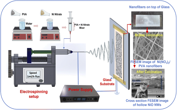 | ||
| Fig. 1 Schematic illustration of the fabrication of NiO NWs on the glass substrate using the electrospinning process. | ||
2.2. Photocatalysis measurements
The NiO NW samples were tested by analyzing the photodegradation of MB and Rhodamine B (RhB) solution in different degradation processes. Before the photocatalytic experiments, the adsorption kinetics of the NiO NW catalyst were studied using 2 × 10⁻⁵ M aqueous MB and RhB dye solutions (10 mg L−1, 240 mL). Using a UV-Vis absorptance spectrophotometer, the dye concentration was determined by monitoring at 664 nm wavelength; also, the as-prepared NiO NWs on glass substrate samples were subsequently tested. The UV-Vis absorption spectra were obtained in the wavelength range of 400–800 nm and the degradation efficacy of MB was visually represented by the relationship C/C0, where C0 and C denote the concentrations of MB before and following the deterioration process, respectively. In addition, photoluminescence analysis was carried out using a spectrofluorometer model Fluoromax-3 with the MB sample excited at 500 nm. After deterioration, the emission spectra of the MB solutions were measured in the wavelength range of 520–820 nm. The experimental measurements were repeated, and the average of the two results was recorded prior to removing the samples.2.3. Analytical techniques
The shape and size of the electrospun NiO fibers were evaluated using field-emission scanning electron microscopy (JEOL model JSM-7610F), and their crystalline structure was determined from the X-ray diffraction patterns (Dmax2100-Rigaku, Bruker). A UV-Vis spectrophotometer was used to determine the UV-Vis absorption spectrum (UV-1700, Shimadzu Corporation, Japan). Thermogravimetric (TGA) analysis was used better to identify the thermal breakdown of electrospun composite fibers. Thermogravimetric analysis was performed using a PerkinElmer prototype Pyrex-1 and an alumina test holder, with samples heated at 10 °C min−1 rate up to 750 °C under nitrogen flow. XPS (X-ray photoelectron spectroscopy, Intercovamex) was employed to determine the binding energies of the chemical groups of calcined NiO NWs. At room temperature, the photoluminescence spectra of NiO were obtained using a fluorescence spectrometer (FLS920, Edinburgh Instruments, UK) attached with a xenon lamp as a source of excitation. For transmission electron microscopy (TEM) (JEOL 2010F Electron Microscopy) analysis, the calcined NWs dispersed in water and bath were sonicated to create a dilute suspension, a droplet of this freshly sonicated suspension was put on a copper grid with a mesh size of 300 and a thin carbon support layer, and the grids were dried for 1 h at 80 °C in an oven prior to TEM analysis.3. Results and discussion
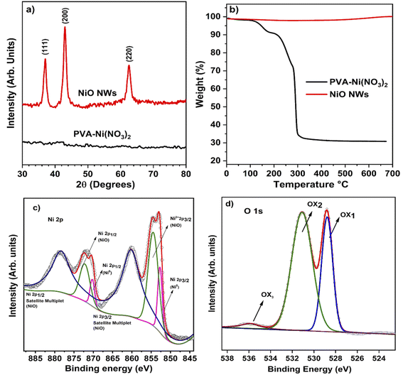
The conceptual depiction of the electrospinning system and the FESEM image of the as-deposited PVA–Ni nitrate composite fibers are shown in Fig. 1. The primary idea of the electrospinning process is the achievement of a high density of precursor fibers on the glass substrate. After calcination, the precursor fibers convert into hollow NiO NWs, which results in a photocatalyst material with highly active photocatalytic sites for sunlight-driven pollutant degradation. The direct deposition of the catalyst on the large glass substrate area shown in the as-deposited image in Fig. 1 produces the immobilization of the fiber material and its use as a photocatalyst will offer several benefits over nanopowders, notably in the recovery after the pollutant degradation process. The development of these catalyst layers on the glass substrate will provide novel architectures, high surface area, and a simple manufacturing process for degrading the specified contaminants with minimal catalyst leaching. At room temperature, the electrospinning technique was utilized to generate the nickel nitrate/polymer nanofiber combination to prepare the high-density hollow NiO fibers shown in Fig. 1. To create identical nanostructured materials, the nickel nitrate/polymer composite fibers were heated in an air atmosphere to oxidize the Ni precursor and remove the polymer. After this process, the resultant crystalline hollow NiO nanofibers retained their distinctive one-dimensional hollow structure. This route does not require any additional transfer process of these fibers. Therefore, the as-developed hollow NiO NWs were readily available to use as a photocatalytic material.The PVA/Ni(NO3)2 nanofiber composite is generated during the first electrospinning process. During the calcination process, as the temperature is raised up to 250 °C, the solvent quickly evaporates, releasing Ni2+ ions and PVA molecules. Ni2+ may readily reach the outside boundary layer of the shell during this operation due to its smaller size compared to PVA molecules. As evident from the TGA analysis (Fig. 2b), the temperatures of deterioration for Ni(NO3)2 and PVA are about 250 °C. Before the removal of PVA, tiny NiO nanoparticles were generated; as the temperature rises, an increasing number of NiO nanoparticles grow on the surface of the shell layer, while the diameters of the nanofibers decrease owing to the decomposition of PVA. Thus, the compact NiO nanoparticles surrounding the surface of the hollow shell layer may form an outer layer, while the inner layer of NiO tiny particles of the shell may expand due to the high strain strength, leading to the construction of a nanofiber structure with a hollow structure.
3.1. Crystallinity and morphological analysis
The electrospun PVA/Ni(NO3)2 composite nanofibers characterized by XRD revealed an amorphous nature, which is consistent with the amorphous characteristic of the mixed polymer composites produced at ambient temperature. This is seen in the PVA/Ni(NO3)2 nanofiber XRD pattern at the bottom (black) of Fig. 2a, where the diffraction signals are absent. Meanwhile, the XRD pattern at the top demonstrates that NiO nanofibers with a high degree of crystallinity are produced following the thermal treatment at 450 °C in air. The prominent diffraction peaks in this pattern were located at 37.2°, 43.2°, and 62.8° are related to the cubic NiO crystalline phases (1 1 1), (2 0 0), and (2 2 0) planes, respectively (JCPDS no. #47-1049). No other diffraction signals related to other crystalline phases are observed in the pattern. This is an indication that the calcination process produces the complete oxidation of the Ni precursor and that the polymer was degraded and removed from the resultant fibers. This is corroborated by the TGA analysis of the as-electrospun and calcined fibers shown in Fig. 2b. The TGA curve of the as-electrospun fibers displays three different weight losses in the temperature ranges of 30–175, 170–280, and 290–330 °C, respectively. At around 80 °C, the Ni nitrate and PVA composite fibers lose a small amount of weight owing to the evaporation of adsorbed water. Between 30 and 170 °C, the weight loss was roughly 25%, attributed to the evaporation of adsorbed water and the nitrate precursor. The weight loss was 30% between 170 and 320 °C due to the dissolution of nitrates, and at 350 °C, not at all weight loss occurred, implying that the organics were evaporated entirely, and the remains were about 25%. It can be evident that under 350 °C thermal annealing, the whole organic, nitrate groups, and water molecules were eliminated. As seen in the figures, annealing also results in a slight weight reduction (Fig. 2b) displays the TGA curve of the NiO NWs formed by calcination, which shows no apparent weight loss, suggesting that the NWs were composed entirely of the NiO phase.The chemical and compositional characteristics of calcinated NiO NWs were characterized using XPS and its high-resolution Ni 2p XPS spectra reveal that Ni is mostly oxidized (Fig. 2c). Ni2+ 2p3/2 in NiO has a substantial peak at 855.8 eV, whereas NiO exhibits a large peak at 856.8 eV. Ni0 2p3/2 and Ni0 2p1/2 are responsible for two small peaks at 853.5 and 872.5 eV, respectively.44 The gap between the two 2p Ni peaks is 18.08 eV, indicating NiO NWs with a Ni2+ oxidation state. The present binding energies of 861.24 and 879.46 eV correspond to the Ni 2p3/2 and Ni 2p1/2 satellite peaks, respectively. In addition, Fig. 2d depicts the O 1s spectrum of NiO NWs; at 531.1 eV, an asymmetric oxygen peak is observed in the O 1s spectrum. The oxygen peak at O 1s is deconvoluted, revealing three distinct peaks at 528.7, 531.1, and 535.8 eV.36 The peak at 528.7 eV physical adsorption energy is attributed to O 1s (O2−)on the surface of NiO NWs. The adsorbed oxygen is important for vapor sensing; the deconvoluted peak at 531.1 eV corresponds to the lattice oxygen of NiO nanograins. The elevation was concentrated on the major peak at 535.1 eV, corresponding to the formation of hydroxyl groups on the surface of NiO NWs because of the substrate's sensitivity to environmental conditions. The obtained XPS results were clearly matched with the XRD analysis of NiO NWs, indicating the presence of OH groups adsorbed on the surfaces of NiO NWs and the formation of Ni vacancies during heat treatment. Noteworthily, the absence of impurities was identified during the pure NiO NW synthesis process.
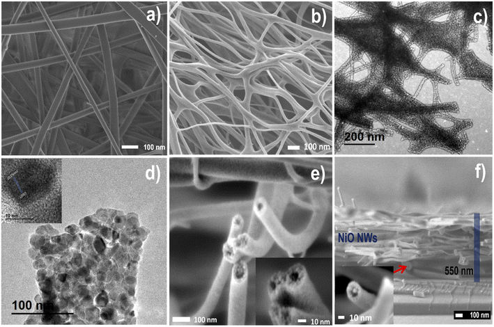
FESEM and TEM analysis studied the morphology and hollow nanostructure of electrospun and NiO NWs. Fig. 3 illustrates the typical FESEM images of (a) and Fig. S1† as electrospun PVA/Ni nitrate composites composed of large-scale 1D nanofiber structures in the length of several micrometers. Also, after the heat treatment, the FESEM images shown in (b and e) and Fig. S2† show that the calcination process reduces the average diameter of the nanofibers from about 120 to 80 nm. This diameter reduction of the nanofibers obeys the elimination of the polymer and the crystallization of NiO, following sample calcination at 450 °C, as is evident from the TGA analysis. The fact that fibers and NiO films concurrently create a NiO phase during the heat treatment presumably enhances the adhesion and density on a glass substrate. Along with the change in the diameter, it is worth noting that after the heat treatment, the NWs were rough on the surface and hollow on the interior, a characteristic that was notably different from that of the as-spun nanofibers (Fig. 3b and e). Hollow NiO NWs were orientated randomly and have a nest-like hollow structure with a smooth surface in Fig. 3e inset; the higher magnification image clearly reveals the hollow shape of the NiO NWs. TEM was used to further explore the structure of these hollow NiO NWs (Fig. 3c and d), and Fig. S3† demonstrate that these NWs are constituted by crystalline nanoparticles randomly linked forming a hollow shape, resulting in many fiber surfaces and voids within the fiber, and these nanoparticles embedded within the fibers are about 30 nm in size. The high-resolution HRTEM image in Fig. 3d inset revealed lattice fringes with a plane spacing of 0.21 nm, which matched the nickel oxide lattice planes (200) from the XRD analysis. While the hollow shape facilitated ion transport, the one-dimensional nature favored electron travel by providing linked paths in the nanofiber entanglement, enhancing the fibers' specific surface area and providing more active sites for ion transport and adsorption.45
Elemental mapping is utilized to study the chemical composition of hollow NiO NWs shown in Fig. S4.† The color difference between the uniform NiO NW fibers composed of Ni, O, and C components and their distribution is homogeneous, showing the homogeneous distribution of hollow NiO NW structures. Taking Ni and O mapping as an example, the complete coverage of cyan blue and green dots across the chosen NWs confirms the homogeneous distribution of Ni and O in NiO NWs. Compared to the dense portion near the middle of the edge, these green dots are sparse inside, demonstrating the hollow structural aspect of the structure. A FESEM cross-section micrograph of the hollow NiO NWs on a glass substrate is shown in Fig. 3f; also, the inset on this image clearly emphasizes the hollow structure, and the uniform thickness of the fiber layer is observed. The outer diameter of NiO nanostructured fibers is several micrometers with 20 nm wall thickness. The formation of composite nanofibers by electrospun, followed by oxidation at the calcination process, resulted in NWs composed of hollow NiO NWs with a diameter of a few nanometers. The solid Ni nanocrystals were transformed into hollow NiO nanospheres by the well-known nanoscale Kirkendall diffusion46 mechanism during the subsequent heating process. The oxidation of a Ni nanocrystal surface results in the formation of an intermediate NiO hollow structure.
3.2. Photocatalytic analysis
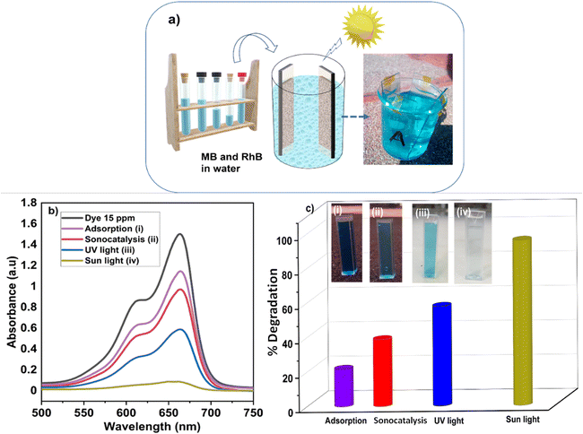
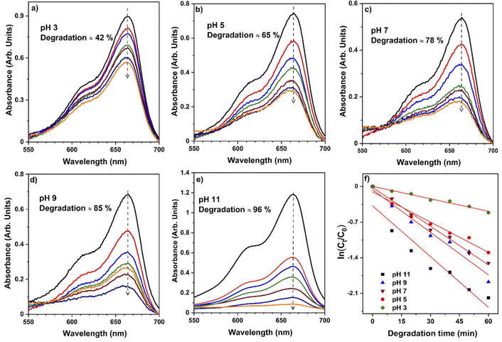
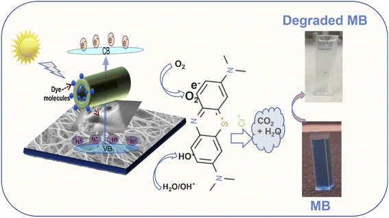
To validate the photocatalytic efficiency of the hollow NiO NWs immobilized on the glass slide substrates, they were immersed in the MB solution and exposed to sunlight. The scheme of the photodegradation process is depicted in Fig. 4a as well as a real-time test image of the NiO NWs on the top of the glass substrates (four) immersed in the MB solution. The total weight% of these NWs is 50 μg (12.5 μg each); it is worth mentioning that electrospun fibers often have a low weight rate in comparison to other synthetic methods.47 The strong adhesion of NWs on the glass substrate exhibited in Fig. 1 was further calcined at a high temperature to get coatings of NWs with high crystallinity and mechanical stability. The benefit of electrospinning large area fibers on top of a substrate was exploited for an economical and straightforward degradation procedure. This approach offers advantages over the photodegradation processes that employs nanopowder photocatalysts since their extraction and reutilization is a tedious task. The immobilization of the NiO NWs through the adhesion to the glass substrates makes their reutilization easy in successive photodegradation experiments. For this, the photocatalysts are just removed from the MB solution after the experiment and gently washed prior to reuse.They further analyzed the discoloration of the MB solution by the UV-Vis spectra related to the NiO NW catalyst by various periods under adsorption and sun light irradiation. As shown in Fig. 4b, the spectra illustrate the discoloration of MB solutions' containing 50 μg fiber at various periods in the dark and when exposed to sunlight for 60 min. It is presumed that the two dimethylamine-substituted aromatic rings are linked through sulfur and nitrogen to form a conjugation system at 664 nm and 615 nm; the dye dimers are supposed to be absorbed by the light that they emit. As shown in Fig. 4b, the MB solution exhibits a minor stain, as shown by the modest reduction in the strength of the MB absorption bands intensities from 1.3 to 1.0. On the other hand, when exposed to sunlight, the NiO NWs cause a gradual discoloration of the MB solution, with the absorption bands disappearing after 1 h, indicating the full decoloration of the MB solution. These tests show that sunlight degradation is the most effective dye removal method, and they are being followed up with experiments using sunlight as an energy source and NiO NWs as a catalyst to determine the efficiency.
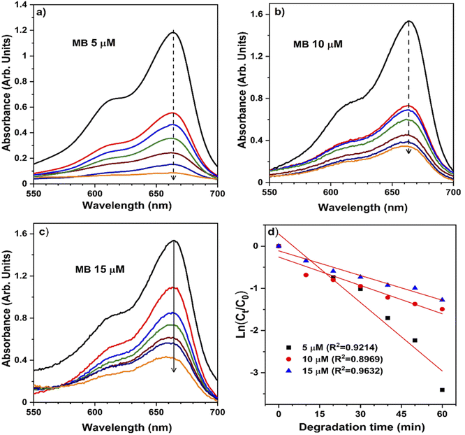
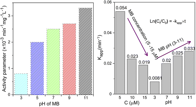
The pH bar chart demonstrates the activity parameter effect of the higher pH medium as described previously and the effect of the concentration given in Fig. 7 to compare the NiO NW photocatalyst's efficiency. These observations with the Kapp and regression coefficient (R2) calculations were explained by the fact that the pH of the media semiconductor metal oxides modifies the electrical double layer at the solid-electrolyte interface.52 Due to a positive charge on the surface of NiO, MB molecules exhibit repulsive behavior in acidic environments. As a result, the degradation efficiency in primary media was poor. There is a negative charge on the surface of the NiO NWs, which makes them even more appealing to the dye molecules. This increases the photocatalytic of NiO NWs when exposed to sunlight. This finding can be explained by the charge on the NiO surface that interacts with the charge on the dye.
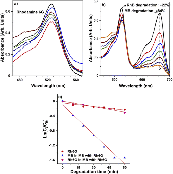 | ||
| Fig. 8 Selective degradation of methylene blue: UV-Vis absorbance spectra of (a) RhB dye and (b) mixed dyes (MB + RhB) throughout degradation, (c) degradation of dyes in combination and individually. | ||
The breakdown of the structure (chromophore) responsible for the dye's color indicates that only a minimal amount of RhB deterioration was found in the absence of the catalyst, indicating that RhB dye is more resistant to visible light; moreover, a degradation rate of 27% of RhB was reported. Also, the mixed dye photocatalytic degradation gradually increases to approximately 90%, as demonstrated in Fig. 8c. It clearly shows that the hollow NiO NW catalyst may function like an effective photocatalyst for the degradation of mixtures of dyes under sunlight, similar to individual dye degradation. Almost all organic dyes constituted of chemically robust and degradation resistant chromophore groups. In addition, an excellent photocatalyst for the textile effluent treatment as wastewater contains a high concentration of organic dyes.
3.3. Stability and reusability of the catalyst
Stability and reusability are critical factors in selecting a cost-effective and viable catalyst for pilot-scale remediation systems.55 Our novel route provides immobilized NiO photocatalysts, which, after removing from the degraded MB solution, can be readily reused. After five recycles for the catalytic degradation of MB, NiO NWs showed only a minor reduction in the catalytic activity. The degradation efficiency of the NiO NW catalyst shows ranges up to 93% even after the catalysts have been used multiple times, indicating that this catalyst has a high degree of stability. Fig. 10 shows the FESEM images of the NiO NW photocatalysts after being used successively in (I) 1 to (V) 5 MB photodegradation experiments. It was observed that even after numerous cycles, there was no discernible change in the morphology of the as-prepared catalyst; only a slight change in the size of the NWs can be observed. Further, the XRD patterns of each recycled catalyst are identical, suggesting that the catalyst has a stable structure during adsorption and photocatalysis.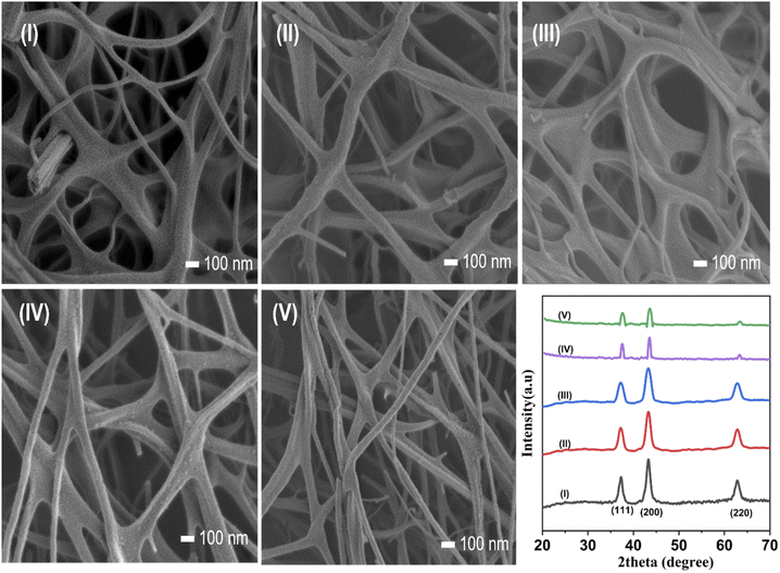 | ||
| Fig. 10 (I–V) FESEM image of each recycled morphology and the XRD patterns show the high degree of stability of the catalyst. | ||
After five consecutive high-efficiency cycles, the percentage photoactivity of the NiO NWs dropped from total 96% by only 0.5% (Fig. S7†). This modest reduction in the photocatalytic activity might be ascribed to the material losses that may occur during the recovery stage (washing and drying), resulting in reduced dosage in the following cycle, lowering the surface catalytic activity, and slightly deteriorating performance.56 During the 4th and 5th cycles, the characteristics of the NW size and density of fibers slightly reduced with evidence from the FESEM and XRD patterns. The adsorptive catalytic surface activity of the catalyst rapidly reduced after each cycle due to catechol and its intermediates obstructing the pores and active sites.57,58 In general, many cycles utilizing the same material may be carried out with almost the same pollutant degradation effectiveness. Therefore, the electrospun hollow NiO NW catalysts developed using a new single-step method have a high degree of stability and effective reusability to degrade dye contaminants. Numerous investigators have investigated the photodegradation of MB during the last few years; Table 1 summarizes the catalytic performances of NiO photocatalysts. It is clear that the hierarchically organized direct deposition of hollow NiO NWs as the photocatalyst outperforms the previously reported NiO photocatalyst significantly. In addition, the hierarchical photocatalyst, the fabrication method with relatively little degrading time, and reusability studies provide a photocatalyst powered by sunlight for the elimination of MB.
| Catalyst | Synthesis method | Catalyst (mg) | Light source | Time (min) | Deg. (%) | k (min−1) | Ref. |
|---|---|---|---|---|---|---|---|
| NiO | Hydrothermal | 100 | UV | 150 | 85 | 0.0856 | 33 |
| NiO | Hydrothermal | 30 | Halogen | 180 | 88 | NA | 59 |
| NiO | Sol–gel | 50 | UV | 270 | 80 | NA | 31 |
| NiO | Combustion | 40 | UV | 180 | 96 | 0.0209 | 60 |
| NiO | Sol–gel | NA | Visible | 270 | 89 | NA | 61 |
| NiO | Thermal decom. | 100 | UV | 360 | 90 | NA | 62 |
| NiO | Hydrothermal | 30 | Xenon | 120 | 60 | 0.0252 | 63 |
| NiO | Hydrothermal | 5 | Visible | 120 | 95 | 0.083 | 64 |
| NiO–ZnO | Green syn. | 50 | Visible | 60 | 88 | 0.036 | 65 |
| NiO–Ag | Hydrothermal | 20 | UV | 210 | 70 | NA | 66 |
| NiO–ZnO | Electro spun | 100 | UV | 180 | MB: 65 | 0.097 | 67 |
| RhB: 59 | |||||||
| NiO–CdS | Sol–gel | 80 | Hg | 90 | 86 | NA | 14 |
| NiO | Electro spun | 50 μg | Sun | 60 | 96 | 0.054 | T. W. |
4. Conclusion
The immobilization of the hollow NiO NW photocatalyst was achieved from a one-step fabrication route by the calcination of electrospun PVA–Ni(NO3)2 fibers collected on glass substrates. Through a simple electrospun technique and subsequent thermal annealing, NiO hierarchical hollow NWs containing nanosized NiO particles were developed. The hollow NiO NWs, with several microns length and 75 nm diameter, were constituted by NiO crystalline nanoparticles with cubic structure, forming a dense and porous layer adhered to the glass substrate. The immobilized NiO NWs were tested for the degradation of MB in solutions exposed to sunlight radiation. The MB photodegradation was analyzed as a function of the MB concentration and pH of the solutions. In addition, the NiO NW photocatalyst could efficiently photodegrade a mixture of dye contaminants. Taking advantage of the immobilization of the hollow NiO NWs, recycling experiments showed the highly efficient photodegradation of MB in subsequent experiments, with degradation percentage in the range of 94–96% in 1 h of exposure to sunlight irradiation. This demonstrates the stability and reusability of the immobilized NiO NW photocatalyst. The comparison of the photocatalytic efficiency for the degradation of MB in the aqueous solutions of the NiO NWs with that reported for other NiO-based photocatalysts reveals equivalent and even superior results. The technique described in this paper might be used to create metal oxide NWs made of controlled-size hollow nanospheres for a variety of applications, including photocatalytic applications.Conflicts of interest
There are no conflicts to declare.Acknowledgements
The authors are grateful for the technical support from Orlando Cortazar and Carlos Alberto Avila. Partial financial support from CONACYT-Mexico is greatly acknowledged. N. K. R. B. acknowledge Dirección General de Asuntos del Personal Académico (DGAPA) de la UNAM for postdoctoral fellowship.References
- F. F. Wang, Q. Li and D. S. Xu, Recent Progress in Semiconductor-Based Nanocomposite Photocatalysts for Solar-to-Chemical Energy Conversion, Adv. Energy Mater., 2017, 7(23), 1–19, DOI:10.1002/aenm.201700529.
- X. Li, J. Yu, J. Low, Y. Fang, J. Xiao and X. Chen, Engineering Heterogeneous Semiconductors for Solar Water Splitting, J. Mater. Chem. A, 2015, 3(6), 2485–2534, 10.1039/c4ta04461d.
- C. Karthikeyan, P. Arunachalam, K. Ramachandran, A. M. Al-Mayouf and S. Karuppuchamy, Recent Advances in Semiconductor Metal Oxides with Enhanced Methods for Solar Photocatalytic Applications, J. Alloys Compd., 2020, 828, 154281, DOI:10.1016/j.jallcom.2020.154281.
- J. J. Rueda-Marquez, I. Levchuk, P. Fernández Ibañez and M. Sillanpää, A Critical Review on Application of Photocatalysis for Toxicity Reduction of Real Wastewaters, J. Cleaner Prod., 2020, 258, 120694, DOI:10.1016/j.jclepro.2020.120694.
- J. He and C. Janáky, Recent Advances in Solar-Driven Carbon Dioxide Conversion: Expectations versus Reality, ACS Energy Lett., 2020, 5(6), 1996–2014, DOI:10.1021/acsenergylett.0c00645.
- L. Wang, W. Lu, D. Ni, T. Xu, N. Li, Z. Zhu, H. Chen and W. Chen, Solar-Initiated Photocatalytic Degradation of Carbamazepine on Excited-State Hexadecachlorophthalocyanine in the Presence of Peroxymonosulfate, Chem. Eng. J., 2017, 330(August), 625–634, DOI:10.1016/j.cej.2017.07.172.
- P. V. R. K. Ramacharyulu, J. Praveen Kumar, G. K. Prasad and B. Sreedhar, Sulphur Doped Nano TiO2: Synthesis, Characterization and Photocatalytic Degradation of a Toxic Chemical in Presence of Sunlight, Mater. Chem. Phys., 2014, 148(3), 692–698, DOI:10.1016/j.matchemphys.2014.08.036.
- G. Liao, C. Li, X. Li and B. Fang, Emerging Polymeric Carbon Nitride Z-Scheme Systems for Photocatalysis, Cell Rep. Phys. Sci., 2021, 2(3), 100355, DOI:10.1016/j.xcrp.2021.100355.
- P. Shandilya, S. Sambyal, R. Sharma, P. Mandyal and B. Fang, Properties, Optimized Morphologies, and Advanced Strategies for Photocatalytic Applications of WO3 Based Photocatalysts, J. Hazard. Mater., 2022, 428(January), 128218, DOI:10.1016/j.jhazmat.2022.128218.
- M. Makaremi, S. Grixti, K. T. Butler, G. A. Ozin and C. V. Singh, Band Engineering of Carbon Nitride Monolayers by N-Type, P-Type, and Isoelectronic Doping for Photocatalytic Applications, ACS Appl. Mater. Interfaces, 2018, 10(13), 11143–11151, DOI:10.1021/acsami.8b01729.
- M. Miyauchi, Y. Nukui, D. Atarashi and E. Sakai, Selective Growth of N-Type Nanoparticles on p-Type Semiconductors for Z-Scheme Photocatalysis, ACS Appl. Mater. Interfaces, 2013, 5(19), 9770–9776, DOI:10.1021/am402929d.
- K. Chandra Sekhar Reddy, V. Selamneni, M. G. Syamala Rao, J. Meza-Arroyo, P. Sahatiya and R. Ramirez-Bon, All Solution Processed Flexible P-NiO/n-CdS Rectifying Junction: Applications towards Broadband Photodetector and Human Breath Monitoring, Appl. Surf. Sci., 2021, 568(July), 150944, DOI:10.1016/j.apsusc.2021.150944.
- L. Nkhaili, A. Narjis, A. Agdad, A. Tchenka, A. El Kissani, A. Outzourhit and A. Oueriagli, A Simple Method to Control the Growth of Copper Oxide Nanowires for Solar Cells and Catalytic Applications, Adv. Condens. Matter Phys., 2020, 2020, 5470817, DOI:10.1155/2020/5470817.
- S. Senobari and A. Nezamzadeh-Ejhieh, A P-n Junction NiO-CdS Nanoparticles with Enhanced Photocatalytic Activity: A Response Surface Methodology Study, J. Mol. Liq., 2018, 257, 173–183, DOI:10.1016/j.molliq.2018.02.096.
- L. Wang, J. Ge, A. Wang, M. Deng, X. Wang, S. Bai, R. Li, J. Jiang, Q. Zhang, Y. Luo and et al, ., Designing P-Type Semiconductor-Metal Hybrid Structures for Improved Photocatalysis, Angew. Chem., 2014, 126(20), 5207–5211, DOI:10.1002/ange.201310635.
- S. U. M. Khan and J. O. M. Bockris, A Model for Electron Transfer at the Illuminated P-Type Semiconductor-Solution Interface, J. Phys. Chem., 1984, 88(12), 2504–2515, DOI:10.1021/j150656a016.
- D. Malwal and P. Gopinath, Enhanced Photocatalytic Activity of Hierarchical Three Dimensional Metal Oxide@CuO Nanostructures towards the Degradation of Congo Red Dye under Solar Radiation, Catal. Sci. Technol., 2016, 6(12), 4458–4472, 10.1039/c6cy00128a.
- K. Maeda, Metal-Complex/Semiconductor Hybrid Photocatalysts and Photoelectrodes for CO2 Reduction Driven by Visible Light, Adv. Mater., 2019, 31(25), 1808205, DOI:10.1002/adma.201808205.
- A. Raza, U. Qumar, A. Haider, S. Naz, J. Haider, A. Ul-Hamid, M. Ikram, S. Ali, S. Goumri-Said and M. B. Kanoun, Liquid-Phase Exfoliated MoS2nanosheets Doped with: P -Type Transition Metals: A Comparative Analysis of Photocatalytic and Antimicrobial Potential Combined with Density Functional Theory, Dalton Trans., 2021, 50(19), 6598–6619, 10.1039/d1dt00236h.
- M. Hao, H. Li, L. Cui, W. Liu, B. Fang, J. Liang, X. Xie, D. Wang and F. Wang, Higher Photocatalytic Removal of Organic Pollutants Using Pangolin-like Composites Made of 3–4 Atomic Layers of MoS2 Nanosheets Deposited on Tourmaline, Environ. Chem. Lett., 2021, 19(5), 3573–3582, DOI:10.1007/s10311-021-01235-6.
- L. Liu, Z. Liu, Y. Yang, M. Geng, Y. Zou, M. B. Shahzad, Y. Dai and Y. Qi, Photocatalytic Properties of Fe-Doped ZnO Electrospun Nanofibers, Ceram. Int., 2018, 44(16), 19998–20005, DOI:10.1016/j.ceramint.2018.07.268.
- A. C. Pradhan and T. Uyar, Morphological Control of Mesoporosity and Nanoparticles within Co3O4-CuO Electrospun Nanofibers: Quantum Confinement and Visible Light Photocatalysis Performance, ACS Appl. Mater. Interfaces, 2017, 9(41), 35757–35774, DOI:10.1021/acsami.7b09026.
- N. Rosman, W. N. W. Salleh, F. Aziz, A. F. Ismail, Z. Harun, S. S. Bahri and K. Nagai, Electrospun Nanofibers Embedding ZnO/Ag2 Co3/Ag2 o Heterojunction Photocatalyst with Enhanced Photocatalytic Activity, Catalysts, 2019, 9(7), 1–18, DOI:10.3390/catal9070565.
- L. Yosefi and M. Haghighi, Fabrication of Nanostructured Flowerlike P-BiOI/p-NiO Heterostructure and Its Efficient Photocatalytic Performance in Water Treatment under Visible-Light Irradiation, Appl. Catal., B, 2018, 220, 367–378, DOI:10.1016/j.apcatb.2017.08.028.
- P. Iyyappa Rajan, J. Judith Vijaya, S. K. Jesudoss, K. Kaviyarasu, L. John Kennedy, R. Jothiramalingam, H. A. Al-Lohedan and M. A. Vaali-Mohammed, Green-Fuel-Mediated Synthesis of Self-Assembled NiO Nano-Sticks for Dual Applications-Photocatalytic Activity on Rose Bengal Dye and Antimicrobial Action on Bacterial Strains, Mater. Res. Express, 2017, 4(8), 085030, DOI:10.1088/2053-1591/aa7e3c.
- T. P. Mokoena, H. C. Swart and D. E. Motaung, A Review on Recent Progress of P-Type Nickel Oxide Based Gas Sensors: Future Perspectives, J. Alloys Compd., 2019, 805, 267–294, DOI:10.1016/j.jallcom.2019.06.329.
- M. Imran Din and A. Rani, Recent Advances in the Synthesis and Stabilization of Nickel and Nickel Oxide Nanoparticles: A Green Adeptness, Int. J. Anal. Chem., 2016, 2016, 3512145, DOI:10.1155/2016/3512145.
- Y. Liu, C. Gao, Q. Li and H. Pang, Nickel Oxide/Graphene Composites: Synthesis and Applications, Chem.–Eur. J., 2019, 25(9), 2141–2160, DOI:10.1002/chem.201803982.
- K. Kalantari, A. M. Afifi, H. Jahangirian and T. J. Webster, Biomedical Applications of Chitosan Electrospun Nanofibers as a Green Polymer – Review, Carbohydr. Polym., 2019, 207(October 2018), 588–600, DOI:10.1016/j.carbpol.2018.12.011.
- C. Li, H. Li, G. He, Z. Lei and W. Wu, Preparation and Photocatalytic Performance of ZnO/Sepiolite Composite Materials, Adv. Mater. Sci. Eng., 2021, 2021, 5357843, DOI:10.1155/2021/5357843.
- Z. Sabouri, A. Akbari, H. A. Hosseini and M. Darroudi, Facile Green Synthesis of NiO Nanoparticles and Investigation of Dye Degradation and Cytotoxicity Effects, J. Mol. Struct., 2018, 1173, 931–936, DOI:10.1016/j.molstruc.2018.07.063.
- Z. Sabouri, A. Akbari, H. A. Hosseini, M. Khatami and M. Darroudi, Egg White-Mediated Green Synthesis of NiO Nanoparticles and Study of Their Cytotoxicity and Photocatalytic Activity, Polyhedron, 2020, 178, 114351, DOI:10.1016/j.poly.2020.114351.
- X. Wan, M. Yuan, S. L. Tie and S. Lan, Effects of Catalyst Characters on the Photocatalytic Activity and Process of NiO Nanoparticles in the Degradation of Methylene Blue, Appl. Surf. Sci., 2013, 277(3), 40–46, DOI:10.1016/j.apsusc.2013.03.126.
- R. Tao, S. Yang, C. Shao, X. Li, X. Li, S. Liu, J. Zhang and Y. Liu, Reusable and Flexible G-C3N4/Ag3PO4/Polyacrylonitrile Heterojunction Nanofibers for Photocatalytic Dye Degradation and Oxygen Evolution, ACS Appl. Nano Mater., 2019, 3081–3090, DOI:10.1021/acsanm.9b00428.
- A. Rovisco, R. Branquinho, J. Deuermeier, T. Freire, E. Fortunato, R. Martins and P. Barquinha, Shape Effect of Zinc-Tin Oxide Nanostructures on Photodegradation of Methylene Blue and Rhodamine B under UV and Visible Light, ACS Appl. Nano Mater., 2021, 4(2), 1149–1161, DOI:10.1021/acsanm.0c02782.
- R. Tao, S. Yang, C. Shao, X. Li, X. Li, S. Liu, J. Zhang and Y. Liu, Reusable and Flexible G-C3N4/Ag3PO4/Polyacrylonitrile Heterojunction Nanofibers for Photocatalytic Dye Degradation and Oxygen Evolution, ACS Appl. Nano Mater., 2019, 2(5), 3081–3090, DOI:10.1021/acsanm.9b00428.
- P. Jongnavakit, P. Amornpitoksuk, S. Suwanboon and T. Ratana, Surface and Photocatalytic Properties of ZnO Thin Film Prepared by Sol-Gel Method, Thin Solid Films, 2012, 520(17), 5561–5567, DOI:10.1016/j.tsf.2012.04.050.
- D. Tekin, H. Kiziltas and H. Ungan, Kinetic Evaluation of ZnO/TiO2 Thin Film Photocatalyst in Photocatalytic Degradation of Orange G, J. Mol. Liq., 2020, 306, 112905, DOI:10.1016/j.molliq.2020.112905.
- N. Mohammad and Y. Atassi, Adsorption of Methylene Blue onto Electrospun Nanofibrous Membranes of Polylactic Acid and Polyacrylonitrile Coated with Chloride Doped Polyaniline, Sci. Rep., 2020, 10(1), 1–19, DOI:10.1038/s41598-020-69825-y.
- Y. Zhang, S. M. Zhao, Q. W. Su and J. L. Xu, Visible Light Response ZnO–C3N4 Thin Film Photocatalyst, Rare Met., 2021, 40(1), 96–104, DOI:10.1007/s12598-019-01297-0.
- K. Sahu, S. Choudhary, S. A. Khan, A. Pandey and S. Mohapatra, Thermal Evolution of Morphological, Structural, Optical and Photocatalytic Properties of CuO Thin Films, Nano-Struct. Nano-Objects, 2019, 17, 92–102, DOI:10.1016/j.nanoso.2018.12.005.
- M. Bahmani, K. Dashtian, D. Mowla, F. Esmaeilzadeh and M. Ghaedi, UiO-66(Ti)-Fe3O4-WO3 Photocatalyst for Efficient Ammonia Degradation from Wastewater into Continuous Flow-Loop Thin Film Slurry Flat-Plate Photoreactor, J. Hazard. Mater., 2020, 393(February), 122360, DOI:10.1016/j.jhazmat.2020.122360.
- K. Chandra Sekhar Reddy, P. Sahatiya, I. Santos-Sauceda, O. Cortázar and R. Ramírez-Bon, One-Step Fabrication of 1D p-NiO Nanowire/n-Si Heterojunction: Development of Self-Powered Ultraviolet Photodetector, Appl. Surf. Sci., 2020, 513(January), 145804, DOI:10.1016/j.apsusc.2020.145804.
- K. Maniammal, G. Madhu and V. Biju, Nanostructured Mesoporous NiO as an Efficient Photocatalyst for Degradation of Methylene Blue: Structure, Properties and Performance, Nano-Struct. Nano-Objects, 2018, 16, 266–275, DOI:10.1016/j.nanoso.2018.07.007.
- M. M. Sabzehmeidani, H. Karimi and M. Ghaedi, Visible Light-Induced Photo-Degradation of Methylene Blue by n–p Heterojunction CeO2/CuS Composite Based on Ribbon-like CeO2 Nanofibers via Electrospinning, Polyhedron, 2019, 170, 160–171, DOI:10.1016/j.poly.2019.05.040.
- J. S. Cho, S. Y. Lee, H. S. Ju and Y. C. Kang, Synthesis of NiO Nanofibers Composed of Hollow Nanospheres with Controlled Sizes by the Nanoscale Kirkendall Diffusion Process and Their Electrochemical Properties, ACS Appl. Mater. Interfaces, 2015, 7(46), 25641–25647, DOI:10.1021/acsami.5b08793.
- G. W. Peterson, A. X. Lu and T. H. Epps, Tuning the Morphology and Activity of Electrospun Polystyrene/UiO-66-NH2 Metal-Organic Framework Composites to Enhance Chemical Warfare Agent Removal, ACS Appl. Mater. Interfaces, 2017, 9(37), 32248–32254, DOI:10.1021/acsami.7b09209.
- R. Zuo, G. Du, W. Zhang, L. Liu, Y. Liu, L. Mei and Z. Li, Photocatalytic Degradation of Methylene Blue Using TiO2 Impregnated Diatomite, Adv. Mater. Sci. Eng., 2014, 2014, 170148, DOI:10.1155/2014/170148.
- Y. Yan, M. Zhang, K. Gong, L. Su, Z. Guo and L. Mao, Adsorption of Methylene Blue Dye onto Carbon Nanotubes: A Route to an Electrochemically Functional Nanostructure and Its Layer-by-Layer Assembled Nanocomposite, Chem. Mater., 2005, 17(13), 3457–3463, DOI:10.1021/cm0504182.
- Y. He, D. B. Jiang, J. Chen, D. Y. Jiang and Y. X. Zhang, Synthesis of MnO2 Nanosheets on Montmorillonite for Oxidative Degradation and Adsorption of Methylene Blue, J. Colloid Interface Sci., 2018, 510, 207–220, DOI:10.1016/j.jcis.2017.09.066.
- M. T. Yagub, T. K. Sen, S. Afroze and H. M. Ang, Dye and Its Removal from Aqueous Solution by Adsorption: A Review, Advances in Colloid and Interface Science, Elsevier B.V., 2014, 172–184, DOI:10.1016/j.cis.2014.04.002.
- E. L. Dewalt-Kerian, S. Kim, M. S. Azam, H. Zeng, Q. Liu and J. M. Gibbs, PH-Dependent Inversion of Hofmeister Trends in the Water Structure of the Electrical Double Layer, J. Phys. Chem. Lett., 2017, 8(13), 2855–2861, DOI:10.1021/acs.jpclett.7b01005.
- S. B. Patil, H. S. Bhojya Naik, G. Nagaraju, R. Viswanath, S. K. Rashmi and M. Vijay kumar, Sugarcane Juice Mediated Eco-Friendly Synthesis of Visible Light Active Zinc Ferrite Nanoparticles: Application to Degradation of Mixed Dyes and Antibacterial Activities, Mater. Chem. Phys., 2018, 212, 351–362, DOI:10.1016/j.matchemphys.2018.03.038.
- A. Akbari, Z. Sabouri, H. A. Hosseini, A. Hashemzadeh, M. Khatami and M. Darroudi, Effect of Nickel Oxide Nanoparticles as a Photocatalyst in Dyes Degradation and Evaluation of Effective Parameters in Their Removal from Aqueous Environments, Inorg. Chem. Commun., 2020, 115(January), 107867, DOI:10.1016/j.inoche.2020.107867.
- W. Da Oh and T. T. Lim, Design and Application of Heterogeneous Catalysts as Peroxydisulfate Activator for Organics Removal: An Overview, Chem. Eng. J., 2019, 358(September 2018), 110–133, DOI:10.1016/j.cej.2018.09.203.
- J. R. J. Zaeni, J. W. Lim, Z. Wang, D. Ding, Y. S. Chua, S. L. Ng and W. Oh Da, In Situ Nitrogen Functionalization of Biochar via One-Pot Synthesis for Catalytic Peroxymonosulfate Activation: Characteristics and Performance Studies, Sep. Purif. Technol., 2020, 241(January), 116702, DOI:10.1016/j.seppur.2020.116702.
- M. Kermani, B. Kakavandi, M. Farzadkia, A. Esrafili, S. F. Jokandan and A. Shahsavani, Catalytic Ozonation of High Concentrations of Catechol over TiO2@Fe3O4 Magnetic Core-Shell Nanocatalyst: Optimization, Toxicity and Degradation Pathway Studies, J. Cleaner Prod., 2018, 192, 597–607, DOI:10.1016/j.jclepro.2018.04.274.
- B. Kakavandi, A. Takdastan, S. Pourfadakari, M. Ahmadmoazzam and S. Jorfi, Heterogeneous Catalytic Degradation of Organic Compounds Using Nanoscale Zero-Valent Iron Supported on Kaolinite: Mechanism, Kinetic and Feasibility Studies, J. Taiwan Inst. Chem. Eng., 2019, 96, 329–340, DOI:10.1016/j.jtice.2018.11.027.
- N. Duraisamy, K. Kandiah, R. Rajendran, S. Prabhu, R. Ramesh and G. Dhanaraj, Electrochemical and Photocatalytic Investigation of Nickel Oxide for Energy Storage and Wastewater Treatment, Res. Chem. Intermed., 2018, 44(9), 5653–5667, DOI:10.1007/s11164-018-3446-5.
- H. S. Sumantha, S. Rajagopal, G. Nagaraju, M. Shashank and B. L. Suresha, Facile and Eco-Friendly Combustion Synthesis of NiO Particles for Photodegradation Studies, Chem. Phys. Lett., 2021, 779(March), 138837, DOI:10.1016/j.cplett.2021.138837.
- A. Noua, H. Farh, R. Guemini, O. Zaoui, T. D. Ounis, H. Houadsi and H. Aounallah, Photocatalytic Degradation of Methylene Blue by NiO Thin Films under Solar Light Irradiation, J. Nano Res., 2019, 56, 152–157, DOI:10.4028/www.scientific.net/JNanoR.56.152.
- M. Y. Nassar, H. M. Aly, E. A. Abdelrahman and M. E. Moustafa, Synthesis, Characterization, and Biological Activity of Some Novel Schiff Bases and Their Co(II) and Ni(II) Complexes: A New Route for Co3O4 and NiO Nanoparticles for Photocatalytic Degradation of Methylene Blue Dye, J. Mol. Struct., 2017, 1143, 462–471, DOI:10.1016/j.molstruc.2017.04.118.
- S. Kerli, A. K. Soǧuksu and M. Kavgacl, Production of Nickel Oxide Nanostructure Particles and Their Photocatalytic Degradation of Different Organic Dye, Int. J. Mod. Phys. B, 2020, 34(9), 1–8, DOI:10.1142/S0217979220500812.
- S. Chaudhary, Y. Kaur, B. Jayee, G. R. Chaudhary and A. Umar, NiO Nanodisks: Highly Efficient Visible-Light Driven Photocatalyst, Potential Scaffold for Seed Germination of Vigna Radiata and Antibacterial Properties, J. Cleaner Prod., 2018, 190, 563–576, DOI:10.1016/j.jclepro.2018.04.110.
- K. C. Lalithambika, A. Thayumanavan, K. Ravichandran and S. Sriram, Photocatalytic and Antibacterial Activities of Eco-Friendly Green Synthesized ZnO and NiO Nanoparticles, J. Mater. Sci.: Mater. Electron., 2017, 28(2), 2062–2068, DOI:10.1007/s10854-016-5767-8.
- S. Majumder, S. Bhattacharjee and C. K. Ghosh, NiO/Ag Heterostructure: Enhanced UV Emission Intensity, Exchange Interaction and Photocatalytic Activity, RSC Adv., 2016, 6(61), 56503–56510, 10.1039/c6ra09432e.
- M. M. Sabzehmeidani, H. Karimi and M. Ghaedi, Electrospinning Preparation of NiO/ZnO Composite Nanofibers for Photodegradation of Binary Mixture of Rhodamine B and Methylene Blue in Aqueous Solution: Central Composite Optimization, Appl. Organomet. Chem., 2018, 32(6), 1–15, DOI:10.1002/aoc.4335.
Footnotes |
| † Electronic supplementary information (ESI) available. See https://doi.org/10.1039/d2ra04826d |
| ‡ Authors with equal contribution. |
| This journal is © The Royal Society of Chemistry 2022 |

