 Open Access Article
Directed molecular structure design of coordination polymers with different ligands for regulating output performance of triboelectric nanogenerators†
Jiabin Xiong‡
 *,
Wenjie Wang,
Huijun Du,
Ziqing Zhou,
Aiwei Zhao,
Liwei Mi
 * and
Siru Chen
 *
*
School of Material and Chemical Engineering, Center for Advanced Materials Research, Zhongyuan University of Technology, Zhengzhou, 450007, China. E-mail: siruchen@zut.edu.cn
First published on 20th October 2022
Abstract
A triboelectric nanogenerator (TENG) provides an effective method to harvest mechanical energy from the environment. The morphology and structure of frictional electrode materials of this type of device affect the output performance significantly. Metal–organic coordination polymers (CPs) with special structure advantages offer a vast pool of materials enabling high performances. Two Co-CPs based on terephthalic acid and 2,5-dihydroxyterephthalic acid ligands, respectively, were used to fabricate TENGs. Detailed electrical characterizations of the TENG devices revealed that the introduction of the substituent groups in the organic ligands leads to the structural changes of CPs, which ultimately leads to significant differences in the output performance.
Introduction
Energy is one of the pillars of modern society, and the energy crises around the world have prompted the search for smart technologies to develop clean and sustainable energy sources.1–4 A large amount of mechanical energy exists in the environment, such as tidal energy,5 energy from falling raindrops,6 energy generated during human movement,7 and water wave energy,8 which raises an important question in the field of energy harvesting to address the collection of mechanical energy in the environment. In 2012, triboelectric nanogenerators (TENGs) were designed by Prof. Wang for energy harvesting that exhibited advantages including simple structure, low cost, high energy conversion efficiency, and environmental friendliness,9 which had far-ranging practical applications, such as cathodic corrosion prevention on metallic external electrodes,10–13 clean-air,14 portable power supply,15 and self-powered sensors.16,17The output performance of TENGs is influenced by multiple factors, including device structure, frictional movement mode, and frictional electrode materials.18–23 Previous reports have mentioned a variety of materials that can be used as frictional electrode materials: animal hair,24 plant leaves,25 hydrogels,26 and coordination polymers (CPs).19,27–29 CPs are an attractive kind of porous crystalline materials formed by self-assembly of metal ions and organic ligands through coordination bonds.12,30 Owing to their large specific surface area, controllable regular spatial structure, and wide variety of building blocks, CPs have been rapidly developed over the last few decades.18,31,32 Many applications of CPs have been reported. For example, MOF-5 for methane storage,33 separation of CO2/CH4 mixtures with the MIL-53(Al) metal–organic framework (MOF),34 selective gas adsorption and separation in MOFs,35 and catalysis and metal encapsulation using amine grafted MOFs on their coordinatively unsaturated metal centers.36 Recently, MOFs or CPs have been explored as electrode materials of TENGs.11,12,27–29 The use of CPs as friction electrode materials for TENGs has broadened not only the application area of CP materials, but also the source range of TENG electrode materials. The diverse metal centers and organic ligands in CPs result in a variety of materials, which have different effects on the output performance of TENGs.
In this paper, we report two types of CPs formed from an identical metal center Co and different ligands, which were used as frictional electrode materials to assemble TENG devices. Friction nanogenerator is used to generate AC potential under the action of external driving force, which involves self-polarization; there is no additional power input in the whole process. The effect of organic ligand-modulated CPs as electrode materials on the output performance of TENGs was investigated. The electrochemical characterization showed that TENGs with higher dielectric constants achieved greater output performance, thus providing a search strategy for discovering suitable frictional electrode materials for TENGs.
Experimental
Compound preparation
All the chemical reagents used in this work were purchased through commercial platforms and can be directly used without further purification. Compounds 1 and 2 were prepared on the bases of reported literature37,38 and the detailed procedures are as follows.Synthesis of Co(1,4-BDC)(DMF)n (compound 1)
A solid mixture of Co(NO3)2·6H2O (40 mg, 0.137 mmol) and terephthalic acid (23 mg, 0.137 mmol) was dissolved in a mixed solution of DMF (1 ml), water (1 ml), and ethanol (0.25 ml). The mixed solution was heated in an isothermal oven at 100 °C for 24 h to obtain pink crystals. After washing the crystals with DMF solution several times, they were put in a vacuum oven for drying. Elemental analysis: calcd (%) for C11H11NO5Co: C, 44.61; H, 3.74; N, 4.73. Found: C, 44.37; H, 3.75; N, 4.36. IR (KBr, ν cm−1): 3423 (m), 2926 (w), 1690 (m), 1577 (m), 1381 (s), 1105 (w), 1015 (w), 811 (w), 749 (m), 521 (w).Synthesis of [Co2(dptp)(H2O)2]n (compound 2)
Co(NO3)2·6H2O (8.67 mmol) and 2,5-dihydroxyterephthalic acid (2.43 mmol) were added into 200 ml mixed solution (volume ratio DMF![[thin space (1/6-em)]](https://www.rsc.org/images/entities/char_2009.gif) :
:![[thin space (1/6-em)]](https://www.rsc.org/images/entities/char_2009.gif) CH3CH2OH
CH3CH2OH![[thin space (1/6-em)]](https://www.rsc.org/images/entities/char_2009.gif) :
:![[thin space (1/6-em)]](https://www.rsc.org/images/entities/char_2009.gif) H2O = 1
H2O = 1![[thin space (1/6-em)]](https://www.rsc.org/images/entities/char_2009.gif) :
:![[thin space (1/6-em)]](https://www.rsc.org/images/entities/char_2009.gif) 1
1![[thin space (1/6-em)]](https://www.rsc.org/images/entities/char_2009.gif) :
:![[thin space (1/6-em)]](https://www.rsc.org/images/entities/char_2009.gif) 1) at the same time, and sonicated until uniform. The mixed solution was sealed in an isothermal oven and heated at 100 °C for 24 h and then cooled to room temperature. The crystals were washed with DMF solution three times and put in a vacuum oven for drying. Elemental analysis: calcd (%) for C14H20N2O10Co2: C, 27.61; H, 1.74; O, 36.78. Found: C, 27.60; H, 1.75; O, 36.80. IR (KBr, ν cm−1): 3416 (m), 1636 (s), 1559 (s), 1457 (m), 1409 (s), 1364 (w), 1243 (m), 1197 (s), 1124 (w), 913 (w), 884 (m), 815 (s), 585 (w), 478 (w).
1) at the same time, and sonicated until uniform. The mixed solution was sealed in an isothermal oven and heated at 100 °C for 24 h and then cooled to room temperature. The crystals were washed with DMF solution three times and put in a vacuum oven for drying. Elemental analysis: calcd (%) for C14H20N2O10Co2: C, 27.61; H, 1.74; O, 36.78. Found: C, 27.60; H, 1.75; O, 36.80. IR (KBr, ν cm−1): 3416 (m), 1636 (s), 1559 (s), 1457 (m), 1409 (s), 1364 (w), 1243 (m), 1197 (s), 1124 (w), 913 (w), 884 (m), 815 (s), 585 (w), 478 (w).
Characterizations
Powder X-ray diffraction (PXRD; Rigaku model RINT Ultima III diffractometer) profiles were obtained to explore the structure of the CPs. Surface morphology was determined by field emission scanning electron microscopy (FE-SEM; Zeiss Merlin Compac), and elemental distribution was investigated using energy dispersive spectroscopy (EDS) and the mapping software that came with the FE-SEM instrument. Fourier transform infrared (FT-IR) spectra were obtained using a Thermo iS50 FT-IR with KBr pellets in the range 400–4000 cm−1. X-ray photoelectron spectroscopy (XPS) was conducted with Al Kα radiation as X-ray source using a Kratos AXIS ULTRA X-ray photoelectron microscope. The dielectric constants of compounds 1 and 2 were measured within the range of 103–106 Hz at room temperature. The dielectric constants of compounds 1 and 2 were measured by a compass test platform at room temperature with an impedance analyzer (Agilent 4294A) in the frequency range of 103–107 Hz.Fabrication of CP-based TENGs
Compounds 1 and 2 were used as friction electrode materials to prepare two TENG devices, referred to as BDC-TENG and OH-BDC-TENG, respectively. Identical amounts were ground in different mortars for the same period of time, and then applied uniformly as a coating on the copper tape of the TENGs.Ligand polymers and polyvinylidene fluoride (PVDF) of opposite electrical properties were used as the friction electrode materials on the positive and negative electrode layers, respectively, of the TENGs. At room temperature, the mechanical energy in a real environment was simulated through the cyclic motion of a linear motor to apply external force to the TENGs. The electrode materials of the TENGs were PVDF films with dimensions of 5 cm × 5 cm and films prepared from compounds 1 and 2. Under identical conditions, the Isc and Vo values of the BDC- and OH-BDC-TENGs at 5 Hz were determined. Isc was also measured after connecting the TENGs to a rectifier bridge. The Isc and Vo of the BDC-TENG were tested under different frequencies (1 Hz, 2 Hz, 4 Hz, 6 Hz, and 8 Hz). The charge density σ was also determined. Power density and current under various load resistances were tested. Cycles of charging and discharging of a capacitor with a capacity of 100 μF at 6 V were tested.
Results and discussion
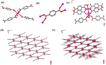
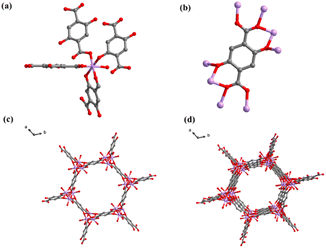
Compounds 1 and 2 were constructed with the same metal center (Co2+) in combination with structurally different ligands (terephthalic acid and 2,5-dihydroxyterephthalic acid). The corresponding crystalline structures of compounds 1 and 2 are shown in Fig. 1 and 2. Compound 1 crystalizes in triclinic space group P![[1 with combining macron]](https://www.rsc.org/images/entities/char_0031_0304.gif) , in which the central Co ion is in a six-coordinate octahedral geometry (Fig. 1a), coordinating with six O atoms from four carboxyl groups of the ligand and two water molecules. Each ligand is connected to four Co ions through four O atoms from two carboxyl groups (Fig. 1b), generating a three-dimensional (3D) reticular structure with rhombic cavities (Fig. 1e). In the crystal structure of compound 2, the central Co ion is coordinated by six O atoms in a twisted octahedral fashion. And it can be seen from Fig. 2 that in addition to the carboxyl group, the hydroxyl group on the ligand has been also deprotonated during synthesis. In fact, all the O atoms in the ligand are involved in the coordination with Co. The central metal Co coordinates with six O atoms, five of which come from the ligand and the sixth from a water molecule. And the five oxygens connected to the metal center come from four ligands, two O atoms from the hydroxyl group in the two ligands, one O atom from the hydroxyl group in the ligand, and two O atoms from hydroxyl and carboxyl group in the same ligands (Fig. 2a). The coordination pattern of the organic ligands of compound 2 is one ligand connected to eight metal-center Co ions, of which six Co2+ are monodentate coordinated with carboxyl hydroxyl groups, and two Co2+ are chelated with carboxyl hydroxyl groups (Fig. 2b). Fig. 2c shows the planar structure of compound 2 along the c-axis, and Fig. 2d shows the 3D structure of compound 2. From Fig. 2c and d, it is clear that compound 2 is a CP with honeycomb topology.
, in which the central Co ion is in a six-coordinate octahedral geometry (Fig. 1a), coordinating with six O atoms from four carboxyl groups of the ligand and two water molecules. Each ligand is connected to four Co ions through four O atoms from two carboxyl groups (Fig. 1b), generating a three-dimensional (3D) reticular structure with rhombic cavities (Fig. 1e). In the crystal structure of compound 2, the central Co ion is coordinated by six O atoms in a twisted octahedral fashion. And it can be seen from Fig. 2 that in addition to the carboxyl group, the hydroxyl group on the ligand has been also deprotonated during synthesis. In fact, all the O atoms in the ligand are involved in the coordination with Co. The central metal Co coordinates with six O atoms, five of which come from the ligand and the sixth from a water molecule. And the five oxygens connected to the metal center come from four ligands, two O atoms from the hydroxyl group in the two ligands, one O atom from the hydroxyl group in the ligand, and two O atoms from hydroxyl and carboxyl group in the same ligands (Fig. 2a). The coordination pattern of the organic ligands of compound 2 is one ligand connected to eight metal-center Co ions, of which six Co2+ are monodentate coordinated with carboxyl hydroxyl groups, and two Co2+ are chelated with carboxyl hydroxyl groups (Fig. 2b). Fig. 2c shows the planar structure of compound 2 along the c-axis, and Fig. 2d shows the 3D structure of compound 2. From Fig. 2c and d, it is clear that compound 2 is a CP with honeycomb topology.
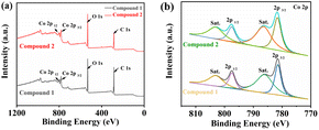
The PXRD profile results for compounds 1 and 2 are shown in Fig. S1a and S1b,† which are consistent with previous reports,37,38 verifying their phase purity. The peaks in the regions of 1457–1577 cm−1 in the FT-IR spectra of compounds 1 and 2 (Fig. S1c and S1d†) could be assigned to the benzene ring. Fig. 3 shows the XPS spectra of the synthesized compounds 1 and 2, which were analyzed to determine the elemental composition and valence states on the surface of the ligand polymers. Fig. 3a shows the full XPS spectra of compounds 1 and 2, including C, O, and Co elements. Fig. 3b presents the energy level analysis of 2p in Co, with two main fitted peaks at 781.83 eV and 787.53 eV, and stable peaks at 786.1 eV and 803 eV, classified as Co 2p1/2 and Co 2p3/2 energy levels, respectively.
There are many factors that affect the output performance of TENGs. The surface roughness, dielectric properties, and area of electrode material play a critical role for the output performance of TENGs.18,39–43 Therefore, we fully ground the block crystals of 1 and 2 into powder and evenly coated on copper tape to improve the output performance of TENGs. Compounds 1 and 2 were used as friction electrode materials to prepare BDC-TENG and OH-BDC-TENG, respectively. The dielectric constants of compounds 1 and 2 were measured to determine the magnitude of their polarities (Fig. S2†). Test results clearly showed that the dielectric constant of compound 1 is higher than that of compound 2, implying a better output performance of BDC-TENG relative to that of OH-BDC-TENG. In addition to the properties of the electrode materials, the tightness of contact between the electrode materials also affects the output performance. Thus, we took the same amount of compounds 1 and 2, ground them into powder in different mortars, and then applied them uniformly as a coating on the copper tape to improve the output performance of TENGs.
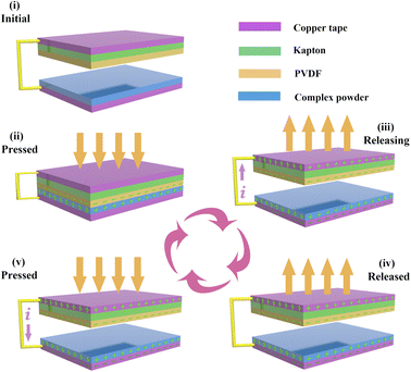
Fig. 4 shows the 3D structure of the CP-TENGs, which adopted a conventional operation mode with vertical contact and separation, where CPs and PVDF with different electronegativity were used as the friction materials on the electrode layers. Simulation of the mechanical energy in a real environment was achieved through the cyclic motion of a linear motor to apply external force to the TENGs. The working principle of TENGs is based on the coupling of triboelectrification and electrostatic induction as shown in Fig. 4. According to the electronegativity difference, PVDF easily gains electrons, whereas CPs can donate electrons because of their conjugated structures. During the periodic contact and separation process, an electric current can flow in a reverse direction due to the existence of potential difference.
Under identical conditions, the Isc and Vo values of the BDC- and OH-BDC-TENGs at 5 Hz were determined to be 76.47 μA and 522.97 V, and 40.67 μA and 388.74 V, respectively (Fig. 5a and b). Clearly, the BDC-TENG had higher Isc and Vo compared to the OH-BDC-TENG. The charge density σ is the integral of current with respect to time, which measures charge transfer and serves as one of the parameters used to evaluate the performance of TENG materials. The σ values for the BDC- and OH-BDC-TENG were calculated as 143.48 μC m−2 and 74.78 μC m−2, respectively (Fig. 5c), with the BDC-TENG clearly showing a relatively large charge density. As expected, the BDC-TENG exhibited a better output performance. The results show that the output performance of the TENGs prepared using Co-CPs was in the following order: BDC-TENG > OH-BDC-TENG. This further confirmed that their output performance was closely related to the variation in the electrode material structures. Due to the difference of chemical structure, the dielectric constant is different. In general, the greater the polarity difference of friction materials, the greater the dielectric constant, and one is more likely to gain electrons and the other is more likely to lose electrons. During the test, more charges will be transferred during the contact electrification process, resulting in more charge output by the TENG, the greater the potential difference between the two electrodes, the larger the TENG output.
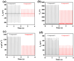 | ||
| Fig. 5 (a) Isc, (b) Vo, and (c) σ for TENGs made from compounds 1 and 2. (d) Isc of TENGs made from compounds 1 and 2 after being connected to a rectifier bridge. | ||
The stability and durability of BDC-TENG were tested at 5 Hz to evaluate the possibility of its practical application. After 35![[thin space (1/6-em)]](https://www.rsc.org/images/entities/char_2009.gif) 000 cycles, its Isc and Vo values remained stable, showing no significant changes (Fig. 6c and d). In addition, Isc and Vo of the BDC-TENG were measured under different frequencies (1 Hz, 2 Hz, 4 Hz, 6 Hz, and 8 Hz) to investigate the effect of the test frequency on the output performance (Fig. 6a and b). The results indicated that the values of Isc and Vo were highly related to the test frequency, both of which trended upwards with increasing test frequency, reaching maximum values of 121.52 μA and 608.51 V at 8 Hz, respectively. Additionally, the output performance of this work is equivalent to or higher than that reported for coordination compound TENG (Fig. S6†).
000 cycles, its Isc and Vo values remained stable, showing no significant changes (Fig. 6c and d). In addition, Isc and Vo of the BDC-TENG were measured under different frequencies (1 Hz, 2 Hz, 4 Hz, 6 Hz, and 8 Hz) to investigate the effect of the test frequency on the output performance (Fig. 6a and b). The results indicated that the values of Isc and Vo were highly related to the test frequency, both of which trended upwards with increasing test frequency, reaching maximum values of 121.52 μA and 608.51 V at 8 Hz, respectively. Additionally, the output performance of this work is equivalent to or higher than that reported for coordination compound TENG (Fig. S6†).
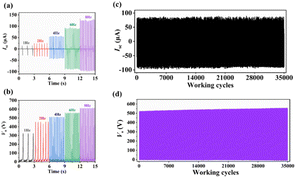 | ||
Fig. 6 (a) Isc and (b) Vo of BDC-TENG at different test frequencies. (c) Isc and (d) Vo for BDC-TENG after 35![[thin space (1/6-em)]](https://www.rsc.org/images/entities/char_2009.gif) 000 cycles. 000 cycles. | ||
The surface morphology of compounds 1 and 2 and PVDF before and after the test was observed by FE-SEM and the elemental distribution of compounds 1 and 2 (Fig. S3–S5†) was investigated using EDS and the mapping software that came with the FE-SEM instrument, which further demonstrate the stability of the friction electrode materials. There was almost no change in the morphology of compounds 1 and 2, indicating that compounds 1 and 2 were relatively stable.
Fig. 7a displays the power density and current under various load resistances, with the instantaneous power peaking at 2635.38 mW m−2 under a load resistance of 5 MΩ. Fig. 7b displays three cycles of charging and discharging of a capacitor with a capacity of 100 μF at 6 V.
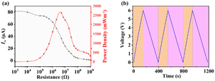 | ||
| Fig. 7 (a) Power density and Isc of BDC-TENG under different loads. (b) Charging–discharging cycles of a 100 μF capacitor by BDC-TENG. | ||
Conclusions
In conclusion, two Co-CPs composed of an identical metal center and slightly different organic ligands were selected as electrode materials for the fabrication of TENG devices. The output performance of the TENGs was evaluated based on the capability of the friction electrode materials to gain or lose electrons. The BDC-TENG with a relatively strong tendency to lose electrons showed superior output performance, further confirming that the performance of the TENG electrode materials (i.e., their capability of losing and gaining electrons) affects the output performance of the TENG. This study shed light on the effect of different organic ligands (microstructural changes) on the output performance of TENGs when CPs were used as their electrode materials. Furthermore, it provides a simple method for designing new electrode materials of TENGs to improve their output performance in the future.Conflicts of interest
There are no conflicts to declare.Acknowledgements
This work was financially supported by the National Natural Science Foundation of China (No. 21901264 and 21902189), Postdoctoral Research Foundation of China (2021M692907), and Young Backbone Teacher of Zhongyuan University of Technology (2020XQG10, 2020XQG09).Notes and references
- X. Kong, Y. Liu, Y. Liu, Y. Zheng, D. Wang, B. Wang, C. Xu and D. Wang, ACS Appl. Mater. Interfaces, 2020, 12, 9387–9394 CrossRef CAS PubMed.
- M. F. Hossain, Int. J. Energy Res., 2016, 40, 1293–1300 CrossRef.
- A. Patel, N. Arora, K. Sartaj, V. Pruthi and P. A. Pruthi, Renewable Sustainable Energy Rev., 2016, 62, 836–855 CrossRef CAS.
- S. Chandrasekaran, C. Bowen, J. Roscow, Y. Zhang, D. K.Dang, E. J. Kim, R. D. K. Misra, L. Deng, J. S. Chung and S. H. Hur, Phys. Rep., 2019, 792, 1–33 CrossRef CAS.
- N. Guillou, G. Chapalain and S. P. Neill, Appl. Energy, 2016, 180, 402–415 CrossRef.
- X. Liu, A. Yu, A. Qin and J. Zhai, Adv. Mater. Technol., 2019, 4, 1900608 CrossRef.
- Y. Xi, J. Hua and Y. Shi, Nano Energy, 2020, 69, 104390 CrossRef CAS.
- T. X. Xiao, T. Jiang, J. X. Zhu, X. Liang, L. Xu, J. J. Shao, C. L. Zhang, J. Wang and Z. L. Wang, ACS Appl. Mater. Interfaces, 2018, 10, 3616–3623 CrossRef CAS PubMed.
- F.-R. Fan, Z.-Q. Tian and Z. Lin Wang, Nano Energy, 2012, 1, 328–334 CrossRef CAS.
- S. Cui, J. Wang, L. Mi, K. Chen, W. Ai, L. Zhai, X. Guan, Y. Zheng and D. Wang, Nano Energy, 2022, 91, 106696 CrossRef CAS.
- W. Wang, Y.-Y. Zhang, S. Zhang, C. Huang and L. Mi, CrystEngComm, 2022, 24, 192–198 RSC.
- Y. Zhang, J. Wu, S. Cui, W. Wei, W. Chen, R. Pang, Z. Wu and L. Mi, Chem.–Eur. J., 2020, 26, 584–591 CrossRef CAS PubMed.
- S. Cui, Y. Zheng, J. Liang and D. Wang, Nano Res., 2018, 11, 1873–1882 CrossRef CAS.
- H. Guo, J. Chen, L. Wang, A. C. Wang, Y. Li, C. An, J.-H. He, C. Hu, V. K. S. Hsiao and Z. L. Wang, Nat. Sustain., 2020, 4, 147–153 CrossRef.
- G. Li, G. Liu, W. He, L. Long, B. Li, Z. Wang, Q. Tang, W. Liu and C. Hu, Nano Res., 2021, 14, 4204–4210 CrossRef CAS.
- Y. Xi, H. Guo, Y. Zi, X. Li, J. Wang, J. Deng, S. Li, C. Hu, X. Cao and Z. L. Wang, Adv. Energy Mater., 2017, 7, 1602397 CrossRef.
- G. Zhu, Y. Su, P. Bai, J. Chen, Q. Jing, W. Yang and Z. L. Wang, ACS Nano, 2014, 8, 6031–6037 CrossRef CAS PubMed.
- G. Khandelwal, N. P. Maria Joseph Raj and S. J. Kim, Adv. Energy Mater., 2021, 11, 2101170 CrossRef CAS.
- G. Khandelwal, N. P. Maria Joseph Raj and S.-J. Kim, J. Mater. Chem. A, 2020, 8, 17817–17825 RSC.
- H. Zhang, Y. Guo, J. Cui, J. Guo, G. Zhao and B. Yang, ChemistrySelect, 2021, 6, 3169–3173 CrossRef CAS.
- S. Ojha, S. Paria, S. K. Karan, S. K. Si, A. Maitra, A. K. Das, L. Halder, A. Bera, A. De and B. B. Khatua, Nanoscale, 2019, 11, 22989–22999 RSC.
- Y. Wang, M. Chao, P. Wan and L. Zhang, Nano Energy, 2020, 70, 104560 CrossRef CAS.
- X. Kang, C. Pan, Y. Chen and X. Pu, RSC Adv., 2020, 10, 17752–17759 RSC.
- M. Singh, A. Sheetal, H. Singh, R. S. Sawhney and J. Kaur, J. Electron. Mater., 2020, 49, 3409–3416 CrossRef CAS.
- Y. Feng, L. Zhang, Y. Zheng, D. Wang, F. Zhou and W. Liu, Nano Energy, 2019, 55, 260–268 CrossRef CAS.
- G. Li, L. Li, P. Zhang, C. Chang, F. Xu and X. Pu, RSC Adv., 2021, 11, 17437–17444 RSC.
- C. Huang, G. Lu, Y. Zhang, K. Zhu, S. Cui, W. Chen, Z. Wu, M. Qiu and L. Mi, Inorg. Chem., 2021, 60, 550–554 CrossRef CAS PubMed.
- Y.-Y. Zhang, M. Hu, Z. Shao, C. Huang, Q. Qin and L. Mi, CrystEngComm, 2021, 23, 5184–5189 RSC.
- G. Khandelwal, A. Chandrasekhar, N. P. Maria Joseph Raj and S. J. Kim, Adv. Energy Mater., 2019, 9, 1803581 CrossRef.
- M. Y. Masoomi, A. Morsali, A. Dhakshinamoorthy and H. Garcia, Angew. Chem., Int. Ed. Engl., 2019, 58, 15188–15205 CrossRef CAS PubMed.
- P. Falcaro, R. Ricco, C. M. Doherty, K. Liang, A. J. Hill and M. J. Styles, Chem. Soc. Rev., 2014, 43, 5513–5560 RSC.
- S. Kitagawa, R. Kitaura and S. Noro, Angew. Chem., Int. Ed. Engl., 2004, 43, 2334–2375 CrossRef CAS PubMed.
- M. Eddaoudi, J. Kim, N. Rosi, D. Vodak, J. Wachter, M. O'Keeffe and O. M. Yaghi, Science, 2002, 295, 469–472 CrossRef CAS PubMed.
- V. Finsy, L. Ma, L. Alaerts, D. E. De Vos, G. V. Baron and J. F. M. Denayer, Microporous Mesoporous Mater., 2009, 120, 221–227 CrossRef CAS.
- J. R. Li, R. J. Kuppler and H. C. Zhou, Chem. Soc. Rev., 2009, 38, 1477–1504 RSC.
- Y. K. Hwang, D.-Y. Hong, J.-S. Chang, S. H. Jhung, Y.-K. Seo, J. Kim, A. Vimont, M. Daturi, C. Serre and G. Férey, Angew. Chem., Int. Ed. Engl., 2008, 120, 4212–4216 CrossRef.
- N. L. Rosi, J. Kim, M. Eddaoudi, B. Chen, M. O'Keeffe and O. M. Yaghi, J. Am. Chem. Soc., 2005, 127, 1504–1518 CrossRef CAS PubMed.
- S. Chen, M. Xue, Y. Li, Y. Pan, L. Zhu and S. Qiu, J. Mater. Chem. A, 2015, 3, 20145–20152 RSC.
- J. Zhang, Y. Zheng, L. Xu and D. Wang, Nano Energy, 2020, 69, 104435 CrossRef CAS.
- Y. Zi, S. Niu, J. Wang, Z. Wen, W. Tang and Z. L. Wang, Nat. Commun., 2015, 6, 1–8 Search PubMed.
- R. D. I. G. Dharmasena, J. H. B. Deane and S. R. P. Silva, Adv. Energy Mater., 2018, 8, 1802190 CrossRef.
- G. Q. Gu, C. B. Han, J. J. Tian, C. X. Lu, C. He, T. Jiang, Z. Li and Z. L. Wang, ACS Appl. Mater. Interfaces, 2017, 9, 11882–11888 CrossRef CAS PubMed.
- M. Flores, M. Garćıa, G. Contreras, A. Mendoza and H. Arellano, RSC Adv., 2021, 11, 416–424 RSC.
Footnotes |
| † Electronic supplementary information (ESI) available. See https://doi.org/10.1039/d2ra05537f |
| ‡ Co first author. |
| This journal is © The Royal Society of Chemistry 2022 |

