 Open Access Article
Preparation of VOC low-temperature oxidation catalysts with copper and iron binary metal oxides via hydrotalcite-like precursors†
Hongwei Zhangab,
Jianjun Li *ab,
Song Shuab,
Jiaxiu Guo
 ab,
Yongjun Liu
 ab,
Wanglai Cen
 ac,
Xinpeng Lid and
Jianrong Yangd
aNational Engineering Research Center for Flue Gas Desulfurization, Sichuan University, Chengdu 610065, China. E-mail: jjli@scu.edu.cn
bCollege of Architecture and Environment, Sichuan University, Chengdu 610065, China
cInstitute of New Energy and Low Carbon Technology, Sichuan University, Chengdu 610065, China
dChongqing Iron & Steel Company Limited, Chongqing 401220, China
First published on 8th December 2022
Abstract
Catalysts are the key to catalytic combustion which is known as an effective method for VOC treatment of industrial waste gas. However, in a typical catalyst, the efficiency of non-noble catalysts, with well economic, is generally poor at catalytic oxidation of VOC from industrial waste gas. In this work, a non-noble catalyst CuFe-4.5 from Cu–Fe elements combined with the properties of hydrotalcite to successfully be prepared. The difference between hydrotalcite as a precursor catalyst and the traditional method was systematically investigated by XRD, FT-IR, SEM, TG, N2 adsorption–desorption isotherms, H2-TPR, O2-TPD, and XPS. By forming the hydrotalcite structure, the structural properties of the derivative oxide catalyst can be optimized and the interaction between Cu and Fe in the system can be strengthened. It is more prone to electrons cycle, has more chemically adsorbed oxygen, facilitates catalyst surface activation and shows better efficiency. The catalyst with high activity for VOC in flue gas at low temperature, with 90% conversion at 236 °C, which is about 60 °C lower than commercial catalysts such as EnviCat® from Clariant, Germany, and also has some advantages over current studies. Our study provides a new perspective on the design of efficient VOC catalysts.
1. Introduction
Volatile organic compounds (VOCs), mainly from industrial emissions, are complex in composition and will have a profound impact on the environment in which we live once they are released into the atmosphere.1–4 Catalytic oxidation is regarded as one of the most promising VOC treatment technologies due to its high efficiency compared to the widely used VOC treatment technologies at present.5,6 The catalysts as the key point of this treatment, noble metal catalysts, containing noble elements like Pt, Pd, etc., are highly active, but they are economically unsuitable for industrial applications.7,8 On the contrary, non-precious metal catalysts with variable valence has a variety of metal energy levels, abundant oxygen-associated anions, higher migration, and electron migration of oxygen or surface active substance, which favor better catalytic activity are widely used for catalytic combustion of current VOCs.9,10The layered double hydroxides (LDH) is a typical anionic clay consisting of divalent and trivalent metal usually, the equation (eqn (1)) is following as:11
| [M1−x2+Mx(OH)23+]x+[Ax/mm−]·nH2O | (1) |
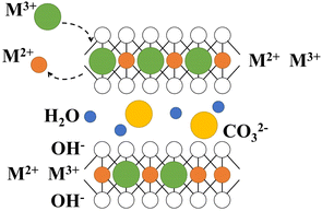
LDH has special layered structure characteristics (Fig. 1), as well as features such as layered and interlayer elements tunability and acid-based bifunctionality, which have led to extensive research in various fields such as biology, medicine, and materials.12
“Cu” is highly active at low temperatures, and Cu-containing catalysts are considered one of the most active catalysts for VOC, which has been a research hotspot in recent years. Hosseini et al.13 synthesized the perovskite-type catalyst LaCu0.5Co0.5O3 and the catalytic efficiency of different metal ions for toluene at 250 °C was 50%. Pan et al.14 reported that the La-doped Cu–Mn metal oxide catalyst achieves 90% removal efficiency at 255 °C for toluene in gas. In addition, few researchers have used hydrotalcite as a precursor to synthesize Cu-contained metal oxide catalysts. Busetto et al.15 synthesize CuZn–Al-LDH to prepare catalytic for methanol catalytic synthesis at low temperatures. Barrault et al.16 also synthesized CuMg–Al-LDH as a precursor to prepare a catalyst for the catalytic hydrogenation of cinnamyl alcohol, showing good catalytic activity and selectivity. “Fe” is cheap and easily available, and when added to Cu-containing systems, it will result in better dispersion of the metal elements, which facilitates better performance in catalytic reactions. A study by Xu et al.17 confirmed that the addition of Fe promoted metal-to-metal interactions and optimized the structure of the catalyst, which was conducive to the synthesis of low-carbon alcohol. Furthermore, compared with most metallic elements, especially precious metals, Cu and Fe are significantly cheaper (Table S2†), offering good economic performance and potential for industrial applications.
The present work attempted to synthesize and characterize CuFe mixed oxide prepared with LDH as precursors for catalytic combustion of toluene. There are still some debates about the synthesis of hydrotalcite and its derivative oxides from Cu and Fe metal elements in particular, and not much research has been done before. As a catalyst precursor, the structure and morphology of LDH will influence the formation of its derivative oxide structure and thus its catalytic combustion performance. The structural and surface features have been characterized by XRD, FT-IR, SEM, and TEM compared with precursors prepared by traditional methods. On this basis, the characterization methods such as TG, N2 adsorption and desorption experiments, H2-TPR, O2-TPD, and XPS were combined to explore the differences in texture properties and REDOX capacity between the derived oxides and oxide of Cu or Fe as catalysts, and explore the optimization role of hydrotalcite structure in the preparation of VOC catalysts from Cu and Fe elements.
2. Experimental
2.1 Material
N2 (≥99.5 vol%) and dried air were provided by Chengdu Xuyuan Chemical Co., Ltd. Cu(NO3)2·3H2O (AR, ≥99.0%), Fe(NO3)3·9H2O (AR), and sodium hydroxide (AR, ≥98.0%) and sodium carbonate (AR) were all obtained from Chengdu Kelong Chemical Co., Ltd. The deionized water came from the water purification system UPR-II-10T of Chengdu Ultrapure Technology Co., Ltd. All the above reagents were not further purified.2.2 Catalysts preparation
According to the attempts in our previous about the influence from the proportion of Cu and Fe in the system and the synthesis method (Fig. S4†). The Cu and Fe catalysts, finally, prepared by co-precipitation method are shown in Fig. S2,† copper nitrate (Cu(NO3)2·3H2O) and ferric iron nitrate (Fe(NO3)3·9H2O) were mixed in a metal salt solution A with a mole ratio of Cu to Fe of 2. Solution B was prepared from sodium hydroxide (NaOH) and sodium carbonate (Na2CO3) in a molar ratio of 1![[thin space (1/6-em)]](https://www.rsc.org/images/entities/char_2009.gif) :
:![[thin space (1/6-em)]](https://www.rsc.org/images/entities/char_2009.gif) 1 at a concentration of 1 M. The 100 mL distilled water was prepared as solution C. The precursor was prepared by the method of low degree of supersaturation: solution A was slowly dripped into solution C by a peristaltic pump at 10 mL min−1 at room temperature. Solution B was used to adjust the pH of the solution to maintain it at 4.5 ± 0.2 or 9.5 ± 0.2, during the drip-adding process. And the pH is an important factor in the formation of hydrotalcite structures. Combined with the two obvious plateaus corresponding to the pH around 4.5 and 9.5 at the previous titration experiments (Fig. S1†), was speculated to may cause the formation of hydrotalcite structure at these pH conditions. After the addition was completed, the mixture was kept stirred for 30 min, placed in a water bath, and reacted at 80 °C for 12 h. After cooling at room temperature, the mixture was repeatedly washed with distilled water until it became neutral and dried overnight at 110 °C, the precursors named CuFe–P-4.5 and CuFe–P-9.5 were obtained, and monometallic oxide precursors named Cu(OH)x and Fe(OH)x were prepared by the same method at pH = 9.5 to further compare the Cu and Fe metal interactions. The precursor was calcined at 400 °C for 4 h, and then the solid was grounded and sieved from 0.5 mm to 1 mm as the catalysts.
1 at a concentration of 1 M. The 100 mL distilled water was prepared as solution C. The precursor was prepared by the method of low degree of supersaturation: solution A was slowly dripped into solution C by a peristaltic pump at 10 mL min−1 at room temperature. Solution B was used to adjust the pH of the solution to maintain it at 4.5 ± 0.2 or 9.5 ± 0.2, during the drip-adding process. And the pH is an important factor in the formation of hydrotalcite structures. Combined with the two obvious plateaus corresponding to the pH around 4.5 and 9.5 at the previous titration experiments (Fig. S1†), was speculated to may cause the formation of hydrotalcite structure at these pH conditions. After the addition was completed, the mixture was kept stirred for 30 min, placed in a water bath, and reacted at 80 °C for 12 h. After cooling at room temperature, the mixture was repeatedly washed with distilled water until it became neutral and dried overnight at 110 °C, the precursors named CuFe–P-4.5 and CuFe–P-9.5 were obtained, and monometallic oxide precursors named Cu(OH)x and Fe(OH)x were prepared by the same method at pH = 9.5 to further compare the Cu and Fe metal interactions. The precursor was calcined at 400 °C for 4 h, and then the solid was grounded and sieved from 0.5 mm to 1 mm as the catalysts.
2.3 Catalytic activity performance
Catalytic performance was evaluated in a fixed-bed reactor shown in Fig. S3.† The reactor was made of a quartz tube with an inner diameter of 8 mm. The VOC emissions from the spraying and drying process in the spraying industry were the foundation for the simulated gas parameters in this experiment. The inlet toluene concentration was set at 1000 ppm. The total flow rate of toluene and air was set at 550 mL min−1. The gas hourly space velocity (GHSV) was controlled at 30![[thin space (1/6-em)]](https://www.rsc.org/images/entities/char_2009.gif) 000 h−1. A thermocouple was used to control and monitor the temperature. Gas concentration was analyzed by gas chromatography coupled with a flame ionization detector (FID, GC-2000III, Shanghai Shangjiqunli Analytic Instrument Co., Ltd.). The temperature range of this experiment was 200–330 °C and the concentration was noted when the temperature was stable and the difference between before and after the measurement was less than 5%. The removal ratio of toluene was calculated as eqn (2):
000 h−1. A thermocouple was used to control and monitor the temperature. Gas concentration was analyzed by gas chromatography coupled with a flame ionization detector (FID, GC-2000III, Shanghai Shangjiqunli Analytic Instrument Co., Ltd.). The temperature range of this experiment was 200–330 °C and the concentration was noted when the temperature was stable and the difference between before and after the measurement was less than 5%. The removal ratio of toluene was calculated as eqn (2):| Toluene removal efficiency (%) = ([toluene]in − [toluene]out)/[toluene]in × 100% | (2) |
2.4 Catalysts characterization
A series of physicochemical analyzes of the prepared precursor and their derived oxides were performed by X-ray diffraction (XRD) using the Bruker D8 ADVANCE diffractometer instrument, Fourier Transform Infrared Spectroscopy (FT-IR) recorded on a Thermo Fisher Nicolet Is10 FTIR spectrometer in the range 4000 to 400 cm−1, scanning electron microscopy (SEM, JEOLJMF-7500 F, Japan), coupled to an Oxford INCA EDX detector system, and transmission electron microscope (TEM, JEOL-JEM2100 Plus, Japan Electronics Co., LTD). Thermal stability analysis was carried out by TG experiment (SDTQ600, TA USA). The texture paraments were determined by the N2 adsorption–desorption method at liquid nitrogen temperature using AUTOSORB-IQ (Quantachrome, USA) and the surface area (BET) was calculated by Brunauer–Emmett–Teller (BET) equation for adsorption curves with relative pressures ranging from 0.05 to 0.35. For the calculation of total pore volume, the N2 adsorption capacity corresponding to the relative pressure of 0.95 was selected. The pore size distribution was calculated from the desorption curve using density functional theory (DFT). A TP-5076 chemisorption analyzer (Tianjin First Industry and Trade Development Co., Ltd., China) was used to perform the H2-temperature-programming reduction (H2-TPR) experiments and the temperature-programmed desorption of oxygen (O2-TPD), and further to investigate the redox ability of catalyst. The surface elements and their valence states of the sample were analyzed with X-ray photoelectron spectroscopy (XPS) with Thermo Scientific EscaLab 250Xi X-ray energy spectrum. Detailed characterization information is described in the ESI.†3. Results and discussion
3.1 Crystal structure and morphological characteristic of the precursors
X-ray diffraction (XRD) can be used to analyze the crystal structure of materials, and hydrotalcite structure materials have a special characteristic diffraction pattern, which is an important means of the analysis of LDH. The characteristic peaks of CuFe–P-4.5 (Fig. 2(a)) are located at 12.8°, 25.7°, and 33.5° corresponding to (003), (006), and (009) peaks of typically hydrotalcite material,18–20 respectively. However, some deviations can be observed compared with conventional hydrotalcite “MgAl-LDH”. It is speculated the tiny deviations are mainly due to the differences in the properties of metallic elements such as Cu–Fe and Mg–Al themselves. On the other hand, the “Jahn–Teller” effect of Cu2+ may be another reason for the deviation, which is also consistent with other research results.20–23 However, CuFe–P-9.5 does not have the characteristic diffraction peaks of hydrotalcite structure, and its peak shape is consistent with malachite (JCPDS: 76-0660) and Fe2O3 (JCPDS: 02-1165). This indicates that Cu2+ and Fe3+ constitute the mixture of various components, mainly malachite, at relatively high pH values rather than the lamellar hydrotalcite structure. The crystal information obtained by the XRD analysis of Jade6 indicates that the CuFe–P-4.5 has a better crystal structure with a crystallinity of 81.82% and a grain size of 59 nm, which contributes to the dispersion of the components in the system and improves the stability and catalytic activity of its derivative oxide catalyst.23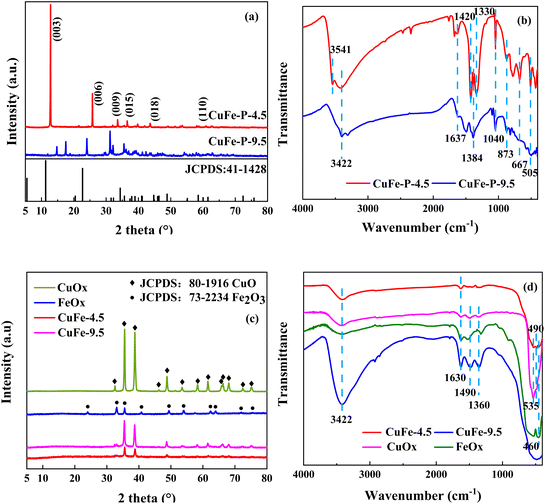 | ||
| Fig. 2 XRD patterns of the precursor (a), and the catalytic (c). FT-IR analysis of the precursor (b), and the catalytic (d). | ||
FT-IR analysis was used to investigate the vibrations of interlayer anions, water, and lattice oxygen of precursor shown in Fig. 2(b). The absorption peak of CuFe–P-4.5 appeared near 3541 cm−1 is attributed to the stretching vibration of hydroxyl in the plate.24 The broad peaks appearing at around 3422 cm−1 and 1637 cm−1 correspond to the stretching and bending vibration of the lattice water hydroxyl groups.23 Asymmetric stretching vibration, out-of-plane deformation vibrations, and in-plane bending vibrations of CO32− were detected at 1328 cm−1, 873 cm−1, and 667 cm−1 respectively, and the adsorption at 1040 cm−1 was considered as the metal skeleton vibration of Cu–O–Fe.25 The peak around 505 cm−1 is the vibration peak of metal bond M–O–H,26 corresponding to the ordered combination of M2+ and M3+, in an ordered combination in the lamellar structure, connected to the hydroxyl group. The structural features of LDH are shown. In contrast, CuFe–P-9.5 showed vibration of water near 3422 cm−1 and 1637 cm−1, and carbonate near 1384 cm−1 and 873 cm−1. The peak shape near 1040 cm−1 corresponded to the interaction of Cu and Fe, which is not obvious compared with the former. It is more consistent with the characteristics of basic copper carbonate.
SEM characterization was used to visualize further the structure and surface characteristics of the precursor intuitively. The CuFe–P-4.5 showed heterogeneous multilayer laminar or laminar aggregates (Fig. 3(a)).24 The thick lamellar structure of CuFe–P-4.5 exhibited, which may be because of the “Jahn–Teller” effect of Cu2+ in the process of forming the lamellar structure, leading to some degree of distortion. Meanwhile, a small amount of impurities can be observed around the layered structure, which is supposed to be caused by the aggregation of semi-finished products forming the lamellar structure or some impurity substances during the preparation process. On the contrary, the precursors prepared at pH = 9.5 (Fig. 3(b)) showed spherical aggregates of 15–35 nm in size, similar to the irregular spherical bouquet of basic copper carbonate.27 The surface of the spheres has many cubic crystals, which may be the Fe2O3 cubic crystal particles. Furthermore, the overlap of multilayer plate-like structures can be observed in TEM shown in (Fig. 3(e)), which is also consistent with the characterization of XRD.
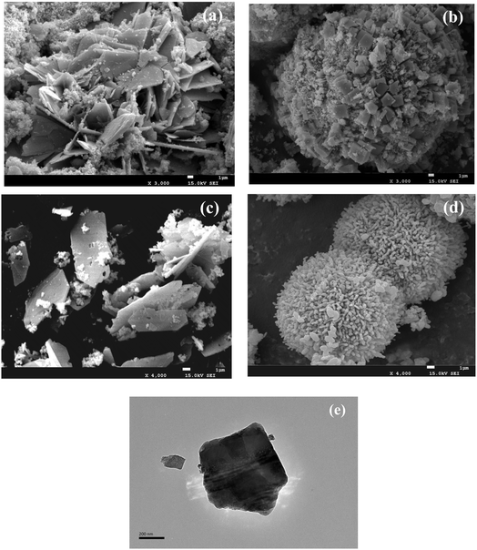 | ||
| Fig. 3 SEM of CuFe–P-4.5 (a), CuFe–P-9.5 (b), CuFe-4.5 (c), and CuFe-9.5 (d); TEM of CuFe–P-4.5 (e). | ||
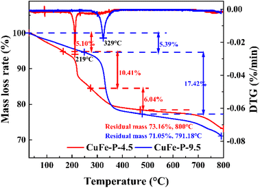
To further explore the conversion process of precursor to its derived oxide and the thermal stability of precursor at a certain temperature, the TG experimental results are shown in Fig. 4. CuFe–P-4.5 exhibited three weight loss processes, with the final residual mass of about 73.16% at 800 °C. In the first stage, the weight loss of 5.10% occurs below 170 °C and corresponds to the release of pore water formed by the adsorption of water molecules from the air by the material. The effective drying of the material before the TG experiment can effectively this part of the weight loss phenomenon.28 When the temperature increases to 170–275 °C, 10.41% of the weight loss corresponds to the second stage, which should be due to the removal of internal crystalline water and hydroxyl groups between the laminates in the structure of the LDH material and the beginning of structural changes in the main laminates. In the third stage, about 6.04% weight loss occurs at 275–472 °C, which corresponds to the removal of the hydroxyl group and interlamellar anion CO32− from the system at high temperature. At this phase, the hydrotalcite lamellar structure collapses, and composite oxides are formed. However, the same preparation CuFe–P-9.5 with Cu and Fe as catalysts showed similar weight loss results in the range of 71.05% to 791.88 °C, but with only two distinct phases in the process. In the first stage, the weight loss rate of 5.39% is similar to that of CuFe–P-4.5, because of the removal of water molecules from the surface. With the increase in temperature from 250 to 477 °C, a significant weight loss (17.42%) is exhibited, which corresponds to the transition from basic copper carbonate to complex metal oxides. In the case of similar weight loss rates, not only did the phase transition process not show, but the phase transition started at higher temperatures. Combined with the fact that the peak position of CuFe–P-9.5 in DTG (329 °C) shifts 110 °C to a higher temperature than the former (219 °C), it indicates that CuFe–P-9.5 has better thermal stability as a precursor and is less likely to transform to its derivative oxide at a certain temperature.
3.2 Catalytic performance test of derived oxides
The precursor is an important step in the process of catalyst preparation. After calcination at a certain temperature, the derived oxide was prepared as toluene combustion catalysts. To explore the interaction of Cu and Fe in the catalyst system, we added CuOx and FeOx prepared under the same conditions as in the comparison. Serious catalytic combustion activity in toluene was measured in a fixed-bed reactor. Table 1 summarizes the temperatures at which the efficiency reached 50% (T50) and 90% (T90) and the catalysts showed significantly different catalytic activity (Fig. 5). It is clear that the two-component catalyst system shows higher catalytic activity at low temperatures, with CuFe-4.5 showing better catalytic activity for toluene at lower temperatures, reaching T50 and T90 at 219 °C and 236 °C, respectively. On the contrary, the single component catalyst of Fe could not even reach 50% removal efficiency at the temperature of about 320 °C. The catalytic activity follows the order of CuFe-4.5 > CuFe-9.5 > CuOx > FeOx.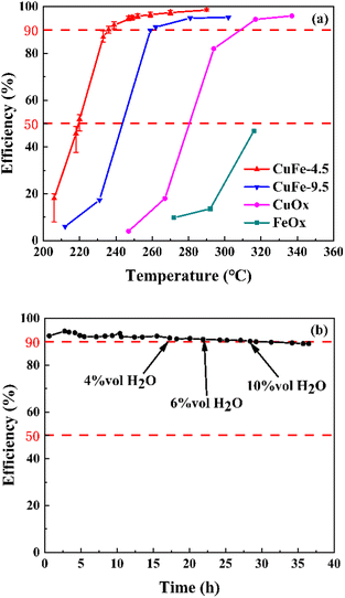 | ||
| Fig. 5 The catalytic performance (a) on the toluene oxidation, and the long period experiment (b) of CuFe-4.5 on the toluene oxidation. | ||
In recent years, based on the better economic performance of non-noble metals, many researchers have explored their use of them to construct catalytic at combustion catalysts for VOC toluene in flue gas, as shown in Table S3.† Cu, Mn, Co, and Ce are used as the main raw materials for the construction of catalysts due to their excellent activity at low temperatures. The catalyst prepared based on Ce and Co exhibits good catalytic performance under the reaction temperature of a minimum of 230 °C.29–31 Furthermore, the catalyst prepared from the combination of Co–Mn, Cu–Mn, and Cu–Ce required higher temperatures (above 258 °C) to achieve the same catalytic efficiency.32–36 Relatively few studies have been conducted on toluene oxidation catalysts with Fe as the main component. Xue et al.37 prepared a 0.1MnCF/IM catalyst by introducing Mn ions from KMnO4 and Djinović et al.38 prepared catalyst Cu005FeKIL(30) by two-step solvothermal short and introduced Cu by impregnation, and the catalyst required a higher than 310 °C temperature to reach the removal efficiency of 90%. In comparison, CuFe-4.5 prepared in this study could provide higher catalytic activity to toluene in flue gas at lower temperatures.
On the other hand, the water resistance test and long period test of CuFe-4.5 were also performed at the GHSV of 30![[thin space (1/6-em)]](https://www.rsc.org/images/entities/char_2009.gif) 000 h−1 in the present water vapor, as shown in Fig. 5. The toluene conversion remained almost constant after introducing 4 vol%, 6 vol%, and 10 vol% water vapor to the stream at 250 °C. The results indicated that water vapor has no obvious impact on the efficiency of toluene conversion within a certain range. When the reaction time reached 36 h, the oxidation efficiency of toluene slightly decreased by about 4%, but still maintained about 90% efficiency. Therefore, CuFe-4.5 is catalytically durable in the simulated flue gas condition, which effectively broadens the application range for practical industrial conditions.
000 h−1 in the present water vapor, as shown in Fig. 5. The toluene conversion remained almost constant after introducing 4 vol%, 6 vol%, and 10 vol% water vapor to the stream at 250 °C. The results indicated that water vapor has no obvious impact on the efficiency of toluene conversion within a certain range. When the reaction time reached 36 h, the oxidation efficiency of toluene slightly decreased by about 4%, but still maintained about 90% efficiency. Therefore, CuFe-4.5 is catalytically durable in the simulated flue gas condition, which effectively broadens the application range for practical industrial conditions.
3.3 Crystal structure and morphology evolution of catalysts
The XRD patterns of the catalyst materials prepared by calcined are shown in Fig. 2(c). CuFe-9.5 shows that the characteristic peaks are superimposed on each other with CuO and Fe2O3, which indicates the metal Cu and Fe constitute a common bimetallic composite oxide. However, for CuFe-4.5 shown, the characteristic diffraction peaks of LDH like (003), (006), and (009) have all disappeared and show that new diffraction peaks appear near 2θ = 35.5°, 38.7°, 48.7°, and 58.2°, corresponding to CuO. It shows that the main structure of LDH is completely lost and the derived oxide with a single structure is obtained. It is worth noting that no diffraction peaks of Fe oxides are observed in CuFe-4.5, which may be due to the amorphous form of Fe oxides generated by calcination of LDH at high temperatures and their homogeneous distribution in the CuO lattice, which is more favorable for the catalytic reaction and the interaction between Cu and Fe in the final catalytic reaction.The vibrations at 3422 cm−1 and 1630 cm−1 of FT-IR analysis of catalyst in Fig. 2(d) correspond to the stretching and bending vibrations of lattice water,23 indicating that a certain amount of lattice water remains in the material after calcination at high temperatures, and these peaks are relatively pronounced at CuFe-9.5. The peaks around 1490 cm−1 and 1360 cm−1 are attributed to the vibration of NO3− and CO32−, respectively. And the peak around 535 cm−1 and 490 cm−1 should respond to the vibration of Cu–O, and 460 cm−1 should respond to the vibration of Fe–O.39,40 The results show that in the catalyst system of CuOx, FeOx, and CuFe-9.5, the impurities such as NO3− and CO32− in the materials are not effectively removed during the calcined process. However, in the pattern of CuFe-4.5, no peaks or weak intensities as mentioned above were observed. And it may benefit from the facilitation effect brought by the LDH structure, which effectively expels impurities from the system and forms stable mono-derivative oxides.
After calcined at high temperature, the surface of CuFe-9.5 has changed significantly, but the distinct spherical structure can still be observed on SEM (Fig. 3(d)), and the crystalline aggregation on the spherical surface has become molten and fine under the high temperature. A significant amount of distortion, craters and pore homogeneous holes on the CuFe-4.5 surface can be observed in Fig. 3(c), although the lamellar structure can be maintained after calcination. These porous structures lead to the gradual expulsion of interlayer water molecules, anions and hydroxyl groups from the hydrotalcite bone structure and the formation of channels during calcination. This phenomenon also further explains, to some extent, the facilitating effect of the unique structure of LDH mentioned in the FT-IR analysis.
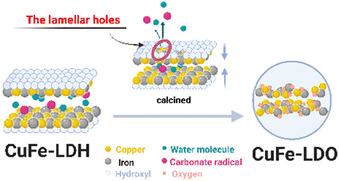
We speculate, combined with the above experimental results (Fig. S5†), that the conversion process of LDH with a multilayer plate-like structure to its derived oxide should have the following characteristics (Fig. 6). The hydroxyl group in the main lamellar structure of CuFe-LDH escapes from the lamellar structure rapidly under the action of high temperature, thus forming lamellar holes. The anions and water molecules between the layers quickly escape from the structural system through the channel formed by the skeleton body of Cu–O–Fe. At the same time, this process will allow the hole to continue to expand, and further increase the effective gain. The derived oxides, finally, with a stable and uniform catalyst system prepared from LDH are formed.
3.4 Structure–property
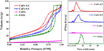
The pore properties of catalysts are important factors for catalytic activity, since the porous structure determines the distribution of active sites and the adsorption capacity. Based on the results of N2 adsorption/desorption isotherms and pore size distribution, the porous structure properties of the catalyst were illuminated. As depicted in Fig. 7, the adsorption/desorption isotherm curves of catalyst, both of which present as the typical type IV adsorption branch. In particular, CuFe-4.5 and CuFe-9.5 show a typical H3 hysteresis loop similarly, with FeOx preferring the H1 type, while the CuOx hysteresis loop is not obvious. The pore size distribution of catalysts is mainly different. The mesoporous structure of CuFe-4.5 and CuFe-9.5 is roughly 3–12 nm, but the catalyst prepared at pH = 4.5 were relatively more concentrated in the lower pore size direction. The pore size distribution of FeOx is mainly concentrated in the range of 7–11 nm, and the distribution of CuOx is relatively uniform. Additionally, the specific surface area (Table 2) of CuFe-4.5 is 83.86 m2 g−1, while that of CuFe-9.5 is only 63.6 m2 g−1. The results indicate that the preparation of catalyst materials by hydrotalcite structure, as the process described before, can promote the optimization of the pore structure of the derived oxide catalyst more than the traditional method, which has a higher specific surface area, higher total pore volume with smaller pore size, and increase the number of pore structure of catalyst materials. In catalytic reactions, better texture properties can often provide better channels for the target components of catalytic combustion in the system, facilitate the “entrance-adsorption-reaction-dissociation” process of substances, and improve the activity of the overall catalyst and the efficiency of catalytic reactions.| Sample | Surface area (BET)/(m2 g−1) | Total pore volume/(cm3 g−1) | Average pore size/(nm) |
|---|---|---|---|
| CuFe-4.5 | 83.86 | 1.687 × 10⁻¹ | 8.05 |
| CuFe-9.5 | 63.6 | 1.653 × 10⁻¹ | 10.4 |
| CuOx | 5.06 | 9.676 × 10⁻³ | 7.64 |
| FeOx | 50.66 | 1.686 × 10⁻¹ | 13.32 |
3.5 H2-TPR and O2-TPD
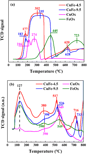
The results of H2-TPR are shown in Fig. 8(a) to investigate the reduction ability of derivative oxides prepared by LDH or conventional methods as catalysts. In monometallic catalysts, the reduction of CuOx is relatively easy, showing H2 consumption at 216 °C and 274 °C, which corresponds to the reduction of Cu2+ → Cu1+ and the conversion of Cu1+ → Cu0 with high partial unsaturation including isolated copper ions and small 2D or 3D clusters,41,42 respectively. However, the reduction of FeOx requires higher temperature, with H2 consumption peaks at about 445 °C and 723 °C corresponding to the further reduction of Fe3+ → Fe2+ and Fe2+ to Fe0,43,44 respectively. It is noteworthy that the CuFe catalyst formed a broad peak in the range of 200 °C to 450 °C with a gentle peak shape. Combined with the analysis of CuOx and FeOx, the interaction between Cu and Fe may make it more susceptible to reduction,45 in which case the adsorbed Cu overflows hydrogen to the refractory Fe under this condition, leading to the reduction of Fe. In other words, the shape of the peaks near 274 °C and 445 °C in the curve shifts toward the middle, and the superposition of the peak shapes form smooth and broad peaks, which reduces the further movement of Fe2+ to lower temperatures. However, in the bimetallic catalytic system, the position of each reduction peak is closer to the low-temperature region compared with monometallic oxide, indicating improved reduction performance. To be specific, the H2 consumption peak of the derived oxide CuFe-4.5 prepared from hydrotalcite as a precursor not only has a lower temperature but also a degree of peak intensity enhancement compared to the conventionally prepared catalyst CuFe-9.5, indicating that the formation of the hydrotalcite structure allows the activation of the catalyst surface at lower temperatures. This implies an improvement in the reduction performance and catalytic performance. This is caused by the transformation of hydrotalcite structure to the derived oxide process, and in conjunction with the above discussion, the laminate structure improves the effective alignment properties of Cu and Fe in the system, and its structural or interlayer ion discharge through-hole properties are not only improve the performance of the texture structure, but also allow better dispersion of the elements in the system and enhance the interaction between Cu and Fe, which in turn improves the overall reduction capacity.O2-TPD measurements were performed to investigate the surface and bulk oxygen and the distribution of three similar peaks is shown in Fig. 8(b). According to the literature,46–48 the peaks at lower temperatures correspond to the desorption of oxygen components adsorbed on the surface, and the peaks between 400 and 600 °C are attributed to surface lattice oxygen components, while higher temperatures correspond to peaks of lattice oxygen. The peak positions were similar across catalysts, with surface adsorbed oxygen desorption peaks occurring at 127 °C and 380 °C. However, the intensity of the peak in the bimetallic catalytic system is strengthened due to the interaction between metals, with CuFe-4.5 being the most pronounced. The same phenomenon can also be observed in the surface lattice oxygen peak shape, especially at around 517 °C, where the comparison between CuFe-4.5 and CuFe-9.5 and the bimetallic compared to the monometallic system shows not only a significant enhancement of the peak intensity but also a constant shift of the peak position to lower temperatures. The results indicate that the lattice oxygen has an increased diffusion rate on the surface material, is easily migrated and desorbed, and has a stronger oxidation capacity. This tendency illustrates that the oxidation performance of the derived oxide catalyst can be optimized by LDH, which is beneficial to exhibit better catalytic activity in catalytic combustion.
3.6 Surface chemical property
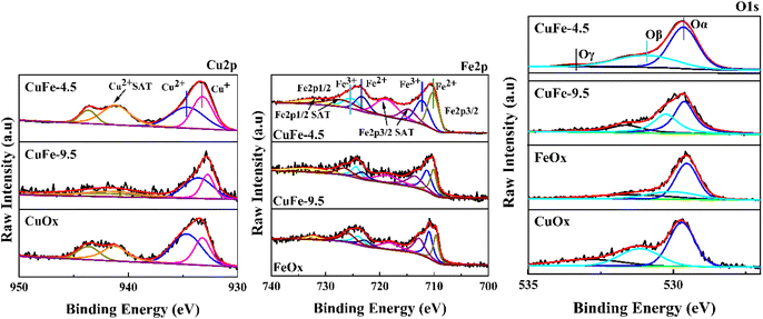
To study the chemical states of the catalysts, XPS measurements of Cu 2p, Fe 2p, and O 1s were conducted. The results are presented in Fig. 9 and Table 3. As exhibited in Fig. 9, the Cu 2p3/2 peaks of all samples show two distinct peaks in the range of 930–947 eV. The peak with the binding energy of 934 eV corresponds to Cu2+ species, and the binding energies in the range of 938–947 eV are the satellite peak of Cu2+ species,43,49 while the peak in the area of low binding energy (933 eV) should be attributed to Cu+ species.50 It indicates that Cu mainly exists in two chemical valence states of Cu2+ and Cu+ in the catalytic. It is worth noting that the proportion of Cu+ in CuFe-4.5 gradually increased compared with CuOx and CuFe-9.5 (Table 3). What's more, Cu+ is the main active substance in the catalyst reaction of toluene, and the increase of its relative content will enhance the oxygen vacancy defect in the catalyst. Therefore, it will be conducive to the adsorption and oxidation of toluene and the improvement of catalytic activity.14| Sample | Surface atomic concentration (%) | |||||
|---|---|---|---|---|---|---|
| I (Cu+) | I (Cu2+) | I (Fe2+) | I (Fe3+) | I (Oα) | I (Oβ) | |
| CuFe-4.5 | 47.82 | 52.18 | 53.89 | 46.11 | 62.43 | 35.71 |
| CuFe-9.5 | 38.28 | 61.72 | 44.75 | 55.25 | 47.39 | 33.85 |
| CuOx | 37.01 | 62.99 | — | — | 50.84 | 30.68 |
| FeOx-500 | — | — | 43.23 | 56.77 | 54.05 | 24.02 |
The same beneficial gain can be found in the Fe 2p3/2 profile, where the peaks of Fe 2p3/2 and Fe 2p1/2 appeared near the binding energy of 705–715 eV and 720–730 eV. The peaks are asymmetric, indicating the presence of Fe in different valence states in the catalyst. It can be divided into two independent peak shapes by fitting, where 709.9–710 eV corresponds to the characteristic peak of Fe2+, and 711.5–711.9 eV is the characteristic peak of Fe3+. The Fe 2p3/2 and Fe 2p1/2 satellite peaks appear in the range of 715–720 eV and 730–740 eV respectively.51,52 In contrast, CuFe-4.5 also showed a higher proportion of Fe2+ in Table 3. It will promote the reaction by conducive the interaction between Cu and Fe by facilitating the electron transfer in the catalytic reaction process. Moreover, to further study the surface oxygen species types of the catalyst, the O 1s peaks of the sample were divided into three independent ones by fitting. The peaks near binding energy 529.6 eV correspond to lattice oxygen in the catalyst denoted as Oα. The surface chemisorbed oxygen corresponds to about 531.2 eV which is denoted as Oβ. The adsorbed oxygen species such as surface water or carbonate showed a less intense acromion 533 eV, denoted as Oγ.14 In particular, surface chemisorbed oxygen is one of the most active oxygen species and plays an important role in promoting catalytic oxidation reactions.53 As parameters of O 1s listed in Table 3, the content of Oβ showed a trend of CuFe-4.5 > CuFe-9.5 > CuOx > FeOx, which is also consistent with the experimental results of the activity test. And it shows that the structure of hydrotalcite as a precursor for catalyst preparation can significantly enhance the interaction between Cu and Fe, the redox electric pair between Fe3+–Fe2+ and Cu2+–Cu+ can be circulated, and the loss of electrons leads to form the vacancy of surface oxygen and lattice oxygen, which is conducive to the formation of chemisorption oxygen on the surface of the catalyst54 and will conducive to the activation of the catalyst surface. It is also consistent with the trend of H2-TPR and O2-TPD.
3.7 Mechanism
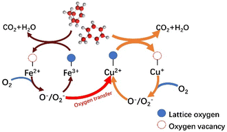
Based on the results of a series of catalysts for catalytic toluene combustion, it is noteworthy that the T50 of CuOx is at least 36 °C lower than that of FeOx in a single-metal system. We suggest that this may be the result of multiple factors, such as the oxidative–reductive properties of materials and differences in surface textures combining the results of characterization such as H2-TPR and O2-TPD. From a general view, the Cu species should play a leading role in the process of catalytic. And the introduction of Fe plays two main roles in the same stage. First, the Fe oxide has certain oxidation–reductive properties, which enhance the catalytic activity of the system as a whole. On the other hand, the presence of Fe leads to a more disordered structure, forming the Cu–Fe interactions and facilitating oxygen transfer in the catalytic system. This should be the main reason for the significantly enhanced catalytic activity compared to the single metal system.Combining the relevant literature55,56 and Mars–van Krevelen (MVK) mechanism, the redox cycle for the catalytic oxidation of toluene over the Cu–Fe catalytic system is described as follows. First, toluene is chemisorbed on the catalyst surface and eventually oxidized to CO2 and H2O at high temperatures. At the same time, with the consumption of lattice oxygen, oxygen vacancies are formed and Cu2+/Fe3+ is reduced to Cu+/Fe2+. The oxygen vacancy, as the site centers of O2 adsorption and activation, play an important role in the lattice oxygen replenishment process. On the other hand, more reduced metal oxides (Cu+/Fe2+) are present on the surface of the catalyst. The distortion of Cu oxides, especially, due to the “Jahn–Teller” effect will lengthen the bond of Cu–O and thus, release the surface lattice oxygen more easily. Second, the oxygen vacancies on the surface act, as electron adsorption centers further activating the adsorbed oxygen to the electron-rich species O− and O2−. And the Cu+ and Fe2+ are gradually oxidized to Cu2+ and Fe3+. It is worth noting that the introduction of Fe can significantly promote the occurrence of catalytic cycle, suggesting that Fe may rapidly transfer oxygen through the path of Fe3+ → Fe2+ → Fe3+. The oxide of Fe3+ belongs to the metal oxide, which generates lattice oxygen through bulk phase reduction, while Fe2+ oxide belongs to the P-type semiconductor oxide, which contains a large number of the center that can provide electrons and adsorb O2, to form reactive oxygen species, which in turn transfer to the Cu cycle pathway: Cu2+ → Cu+ → Cu2+. Cu+ can adsorb reactive oxygen on the surface and obtain activated oxygen from the Fe cycling system, thus facilitating oxygen transfer. Finally, the lattice oxygen formed by linking the activated O species to the valence bands of the metals Cu2+ and Fe3+ replenished the oxygen vacancies generated during the catalytic oxidation of toluene, forming the catalytic cycle. According to the above results and discussion, the total reaction mechanism of catalytic oxidation of toluene with Cu–Fe catalyst (Fig. 10) could be described as follows:
| C7H8 + ˙O2− + ˙O2 → CO2 + H2O | (3) |
| Cu2+ + ˙e → Cu+ | (4) |
| Fe3+ + ˙e → Fe2+ | (5) |
| Cu+ → Cu2+ + ˙e | (6) |
| Fe2+ → Fe3+ + ˙e | (7) |
| O2 + ˙e → ˙O2− | (8) |
By improving the catalyst structure and the connection between metal components, the hydrotalc-prepared catalyst demonstrated higher catalytic activity in the oxidation of toluene. For example, CuFe-4.5 shows no significant FeOx diffraction peak on XRD (Fig. 2(c)), and the phase may be amorphous or microcrystalline, which is more favorable for intermetallic electron transfer and catalytic reactions.
4. Conclusions
In this study, the precursors with the characteristic structure of hydrotalcite were successfully prepared from Cu and Fe, and their structures were characterized through XRD, FT-IR, SEM, and TEM. On this basis, the prepared derivative oxide catalyst named CuFe-4.5 showed better catalytic activity to toluene in the flue gas. The experimental results showed that T50 and T90 were reached at 219 and 236 °C. The differences in chemical and physical properties of CuOx, FeOx and bimetallic oxides (named CuFe-9.5) prepared by conventional methods were analyzed in combination with the characterization of N2 adsorption and desorption curves, H2-TPR, O2-TPD and XPS. We argue that the process of conversion of LDH to its derived oxides corresponds to the gradual loss and transformation of precursors with structural characteristics of hydrotalcite into stable derived oxide structures. And it is the process special that will not only optimize the texture properties, but further strengthens the interaction of Cu and Fe effectively, and the catalyst surface can be activated at lower temperatures. Our study may offer a fresh viewpoint for the design of highly effective catalysts at VOC.Author contributions
Hongwei Zhang: performing the experiments, data analysis, writing – original draft. Jianjun Li: conceptualization, supervision, analysis on the study results. Song Shu: evolution of overarching research goals and aims, writing – review & editing. Jiaxiu Guo: provision of study materials, reagent, and instrumentation. Yongjun Liu: design of methodology and device. Wanglai Cen: management activites to annotate and scrub data. Xinpeng Li, and Jianrong Yang: conducting the investigation process about foundation data from actual factory. We certify that this manuscript consists of original, unpublished work which is not under consideration for publication elsewhere.Conflicts of interest
There are no conflicts to declare.Acknowledgements
This work was supported by National Major Science and Technology Project of China (No. 2019YFC0214404), and Science and Technology Major Projects in Sichuan Province (2019KJT0067-2018SZDZX0019).References
- K. Qiu, L. Yang, J. Lin, P. Wang, Y. Yang, D. Ye and L. Wang, Atmos. Environ., 2014, 86, 102–112 CrossRef CAS
.
- M. Brauer and J. R. Brook, Atmos. Environ., 1997, 31, 2113–2121 CrossRef CAS
.
- R. Huang, Y. Zhang, C. Bozzetti, K.-F. Ho, J.-J. Cao and Y. Han, et al., Nature, 2014, 514, 218–222 CrossRef CAS PubMed
.
- D. D. Rose and G. Worm, Atmos. Environ., 1993, 27, 2243–2245 CrossRef
.
- J. Gutiérrez-ortiz, B. Rivas, R. López-fonseca and J. González-Velasco, Appl. Catal., B, 2006, 65, 191–200 CrossRef
.
- R. Peng, S. Li, X. Sun, Q. Ren, L. Chen and M. Fu, et al., Appl. Catal., B, 2017, 220, 462–470 CrossRef
.
- A. Aranzabal, B. Pereda-Ayo, M. González-Marcos, J. González-Marcos, R. López-Fonseca and J. González-Velasco, Chem. Pap., 2013, 68, 1169–1186 Search PubMed
.
- P. Marécot, A. Fakche, B. Kellali, G. Mabilon, P. Prigent and J. Barbier, Appl. Catal., B, 1994, 3, 283–294 CrossRef
.
- J. Spivey, Ind. Eng. Chem. Res., 1987, 26, 2165–2180 CrossRef CAS
.
- A. Carrillo and J. Carriazo, Appl. Catal., B, 2015, 164, 443–452 CrossRef CAS
.
- N. Gu, J. Gao, K. Wang, B. Li, W. Dong and Y. Ma, J. Taiwan Inst. Chem. Eng., 2016, 64, 189–195 CrossRef CAS
.
- Y. Yuan, X. Zhang, Y. Lei, Y. Jiang, Z. Xu and S. Zhang, et al., J. Taiwan Inst. Chem. Eng., 2018, 87, 73–82 CrossRef CAS
.
- S. Hosseini, D. Salari, A. Niaei and S. Oskoui, J. Ind. Eng. Chem., 2013, 19, 1903–1909 CrossRef CAS
.
- J. Pan, W. Du, Y. Liu, Y. Cheng and S. Yuan, J. Rare Earths, 2019, 37, 602–608 CrossRef CAS
.
- C. Busetto, G. Del piero, G. Manara and A. Vaccari, J. Catal., 1984, 85, 260–266 CrossRef
.
- J. Barrault, A. Derouault, G. Courtois, J. Maissant, J. Dupin and C. Guimon, et al., Appl. Catal., A, 2003, 262, 43–51 CrossRef
.
- R. Xu, C. Yang, W. Wei, W. Li, Y. Sun and T. Hu, J. Mol. Catal. A: Chem., 2004, 221, 51–58 CrossRef CAS
.
- Y. Zhu, J. Rong, T. Zhang, J. Xu, Y. Dai and F. Qiu, ACS Appl. Nano Mater., 2018, 1, 284–292 CrossRef CAS
.
- W. Putro, T. Hara, N. Ichikuni and S. Shimazu, Appl. Catal., A, 2020, 602, 117519 CrossRef CAS
.
- H. Liu, Q. Jiao, Y. Zhao, H. Li, C. Sun and X. Li, et al., Mater. Lett., 2010, 64, 1698–1700 CrossRef CAS
.
- J. Liu, P. Yao, Z. Ni, Y. Li and W. Shi, Acta Phys.-Chim. Sin., 2011, 27, 2088–2094 CAS
.
- H. Yan, J. Lu, M. Wei, J. Ma, H. Li and J. He, et al., J. Mol. Struct.: THEOCHEM, 2008, 866, 34–45 CrossRef CAS
.
- O. Shenderova, A. Koscheev, N. Zaripov, I. Petrov, Y. Skryabin and P. Detkov, et al., J. Phys. Chem. C, 2011, 115, 9827–9837 CrossRef CAS
.
- T. Xue, R. Li, W. Gao, T. Gao, Q. Wang and A. Umar, et al., J. Nanosci. Nanotechnol., 2018, 18, 3381–3386 CrossRef CAS PubMed
.
- L. Liu, S. Li, Y. An, X. Sun, H. Wu and J. Li, et al., Catalysts, 2019, 9, 118 CrossRef
.
- Q. Yang, Y. Zhong, X. Li, X. Li, K. Luo and X. Wu, et al., J. Ind. Eng. Chem., 2015, 28, 54–59 CrossRef CAS
.
- S. Pourmortazavi, I. Kohsari and S. Hajimirsadeghi, Cent. Eur. J. Chem., 2009, 7, 74–78 CAS
.
- S. Yun and T. Pinnavaia, Chem. Mater., 1995, 7, 348–354 CrossRef CAS
.
- D. Yan, S. Mo, Y. Sun, Q. Ren, Z. Feng and P. Chen, et al., Chemosphere, 2020, 247, 125860 CrossRef CAS PubMed
.
- Q. Ren, Z. Feng, S. Mo, C. Huang, S. Li and W. Zhang, et al., Catal. Today, 2019, 332, 160–167 CrossRef CAS
.
- Q. Zou, M. Liu, M. Fan, Y. Ding, Y. Chen and S. Shen, et al., J. Rare Earths, 2020, 39, 409–418 CrossRef
.
- D. Aguilera, A. Perez, R. Molina and S. Moreno, et al., Appl. Catal., B, 2011, 104, 144–150 CrossRef CAS
.
- L. Li, J. Luo, Y. Liu, F. Jing, D. Su and W. Chu, ACS Appl. Mater. Interfaces, 2017, 9, 21798–21808 CrossRef CAS PubMed
.
- S. Saqer, D. Kondarides and X. Verykios, Appl. Catal., B, 2011, 103, 275–286 CrossRef CAS
.
- L. Li, C. Zhang, F. Chen, Y. Xiang, J. Yan and W. Chu, Catal. Today, 2021, 376, 239–246 CrossRef CAS
.
- Y. Zhang, C. Li, Y. Zhu, X. Du, X. Lyu and S. Li, et al., Fuel, 2020, 276, 118099 CrossRef CAS
.
- T. Xue, R. Li, Z. Zhang, Y. Gao and Q. Wang, J. Environ. Sci., 2020, 96, 194–203 CrossRef CAS PubMed
.
- P. Djinović, A. Ristić, T. Žumbar, V. D. B. C. Dasireddy, M. Rangus and G. Dražić, et al., Appl. Catal., B, 2020, 268, 118749 CrossRef
.
- M. Zubair, H. Aziz, I. Ihsanullah, M. Ahmad and M. Harthi, Environ. Technol. Innovation, 2021, 23, 101614 CrossRef CAS
.
- X. Ma, R. Hao, Z. Wang, P. Xu, Y. Luo and Y. Zhao, et al., Chem. Eng. J., 2020, 401, 126101 CrossRef CAS
.
- G. Delahay, E. Ensuque, B. Coq and F. Figuéras, J. Catal., 1998, 175, 7–15 CrossRef CAS
.
- A. Antunes, J. Silva, M. Ribeiro, F. Ribeiro, P. Magnoux and M. Guisnet, Stud. Surf. Sci. Catal., 2001, 135, 325 CrossRef
.
- J. Leith and M. Howden, Appl. Catal., 1988, 37, 75–92 CrossRef
.
- G. Maiti, R. Malessa and M. Baerns, Appl. Catal., 1983, 5, 151–170 CrossRef CAS
.
- D. Bukur, D. Mukesh and S. Patel, Ind. Eng. Chem. Res., 1990, 29, 194–204 CrossRef CAS
.
- X. Zhou, Y. Shang, W. Wei, T. Lin, J. Wang and X. Lai, et al., New J. Chem., 2020, 44, 10859–10869 RSC
.
- J. Feng, Z. Hou, X. Zhou, H. Zhang, T. Cheng and T. Lin, et al., Chem. Pap., 2018, 72, 161–172 CrossRef CAS
.
- N. Miniajluk, J. Trawczyński and M. Zawadzki, Appl. Catal., A, 2017, 531, 119–128 CrossRef CAS
.
- F. Li, L. Zhang, D. Evans and X. Duan, Colloids Surf., A, 2004, 244, 169–177 CrossRef CAS
.
- S. Vepřek, D. Cocke, S. Kehl and H. Oswald, J. Catal., 2004, 244, 169–177 Search PubMed
.
- A. Grosvenor, B. Kobe, M. Biesinger and N. Mclntyre, Surf. Interface Anal., 2004, 36, 1564–1574 CrossRef CAS
.
- T. Yamashita and P. Hayes, Appl. Surf. Sci., 2008, 254, 2441–2449 CrossRef CAS
.
- L. Jing, Z. Xu, X. Sun, J. Shang and W. Cai, Appl. Surf. Sci., 2001, 180, 308–314 CrossRef CAS
.
- J. Li, X. Bai, D. Zhang and H. Li, Appl. Surf. Sci., 2006, 252, 7436–7441 CrossRef CAS
.
- S. Ren, W. Liang, Q. Li and Y. Zhu, Chemosphere, 2020, 251, 126382 CrossRef CAS PubMed
.
- L. Chen, Y. Liu, X. Fang and Y. Cheng, J. Hazard. Mater., 2021, 409, 125020 CrossRef CAS PubMed
.
Footnote |
| † Electronic supplementary information (ESI) available. See DOI: https://doi.org/10.1039/d2ra06611d |
| This journal is © The Royal Society of Chemistry 2022 |

