 Open Access Article
Boosting the electro-oxidation of 5-hydroxymethyl-furfural on a Co–CoSx heterojunction by intensified spin polarization†
Jianmin
Chen
,
Yajing
Wang
*,
Mingjun
Zhou
and
Yingwei
Li
 *
*
State Key Laboratory of Pulp and Paper Engineering, School of Chemistry and Chemical Engineering, South China University of Technology, Guangzhou 510640, China. E-mail: wangyj4302@scut.edu.cn; liyw@scut.edu.cn
First published on 30th March 2022
Abstract
The conversion of biomass-derived platform molecules (e.g., 5-hydroxymethyl furfural (HMF)) represents a sustainable route to produce value-added chemicals. Here we report the fabrication of an N-doped carbon nanotube assembled yolk–shell polyhedron with embedded Co–CoSx nanoparticles (NPs) (Y-Co–CoSx@CN) for efficient HMF electrooxidation. DFT calculations demonstrate that the formation of the heterojunction could intensify spin polarization in Co–CoS2, thus achieving effective d–p coupling between the catalyst and reactant/intermediate. As expected, Y-Co–CoSx@CN exhibits excellent HMF electro-oxidation activity at a low applied potential of 1.29 V vs. RHE at 10 mA cm−2 in 0.1 M KOH with 5 mM HMF, affording an FDCA yield of 96% and FE of 93.5%. This work not only sheds light on the catalytic nature of the heterojunction and the underlying mechanisms for the enhancement of HMF electro-oxidation activity, but would also provide a descriptor for the rational design of advanced electro-catalysts.
1 Introduction
From an environmentally benign and economic perspective, 5-hydroxymethylfurfural (HMF), one of the biomass-derived platform substrates, holds great potential for producing value-added chemicals.1–6 As an example, 2,5-furandicarboxylic acid (FDCA), identified as a promising alternative to petroleum-based terephthalic acid for various functional polymeric materials, can be produced by the oxidation of HMF.7–11 As compared with the conventional thermal oxidation, electrooxidation of HMF is a prospective technique as it allows the reaction to proceed under milder conditions (e.g., 1 atm and 25 °C), without the use of any organic solvents and chemical oxidant agents.12–17Nowadays, non-noble metals (Fe, Co, and Ni) and their phosphides (CoP and Ni2P/Ni foam), sulfides (Ni3S2/Ni foam), oxides (NiCo2O4, and NixCo3−xO4/Ni foam), hydroxides (CuNi(OH)2/C, and NiCoFe-LDHs, CoFe@NiFe-LDHs), and nitrides (Ni3N@C), have been widely investigated as catalysts for HMF electro-catalytic oxidation.18–31 However, the potentials (at 10 mA cm−2) of the reported materials are still higher than 1.35 VRHE, due to the weak d–p coupling between active sites and reactants/intermediates. Thus, many efforts have been devoted to modifying the electronic properties of active sites, such as introducing interface defects or dopants, which could induce the redistribution of the electron density around the metals, giving rise to significantly enhanced electro-catalytic performances. For instance, Zou et al. constructed NiO–Co3O4 to enhance the electro-catalytic performances for HMF oxidation due to the strong interface effect.32 Wang's group fabricated Co3O4 decorated with single-atom Ir, which could promote the adsorption and activation of HMF.33 Although considerable progress has been made, the nature of how the electronic structure impacts the catalytic behavior in the HMF electro-oxidation reaction (HMFOR) remains unexplored. Hence, it is highly desirable to establish a descriptor between activity and the electronic structure for the rational design of HMFOR catalysts.
Recently, studies have indicated that electric polarization can affect the catalytic behavior, thus improving the catalytic activity and selectivity. Kou's group reported that the polarization dependent activation achieved effective control of the limiting potential for CO2 reduction on TM@In2Se3 (TM = Ni, Pd, Rh, Nb, and Re).34 Therefore, electric polarization may serve as a feasible catalytic descriptor to link the electronic structure and catalytic activity for the HMFOR. Furthermore, the increasing interest in the construction of heterojunction interfaces is driven by the pursuit of highly efficient catalysts.35–37 In this regard, it is of great significance to construct the heterojunction catalyst as a model for the investigation of the role of electric polarization.
In this work, we report the fabrication of a Co–CoSx heterojunction embedded in a yolk–shell polyhedron (Y-Co–CoSx@CN) by employing ZIF-67 as the precursor through a pyrolysis-sulfuration strategy. DFT calculations reveal that the intensified spin polarization in Co–CoS2 makes their electronic states move to the Fermi level, which affords the favorable d–p coupling between catalysts and reactants/intermediates, achieving an economical energy input for the overall HMFOR. Consequently, Y-Co–CoSx@CN provides a current density of 10 mA cm−2 at a low overpotential of 1.29 V vs. RHE, with a small Tafel slope of 152 mV dec−1, outperforming all the catalysts previously reported under identical conditions.
2 Results and discussion
2.1 Materials preparation and characterization
The synthesis procedure of yolk–shell Co–CoSx@CN is schematically illustrated in Fig. 1a. First, rhombic dodecahedral ZIF-67 with a size of ca. 800 nm was synthesized (Fig. S1†). Subsequently, ZIF-67 was pyrolyzed at 500 °C under a H2/Ar atmosphere to afford Co@CN with a solid polyhedron (Fig. S2a1–a6 and S3a†). The secondary pyrolysis of Co@CN under an Ar atmosphere obtained yolk–shell polyhedra assembled from N-doped carbon nanotubes with embedded Co nanoparticles (NPs) (denoted as Y-Co@CN-X, X represents the pyrolysis temperature), as observed in Fig. S4.† According to the mechanism of rigid-shell-induced outward contraction, with the proceeding of the secondary pyrolysis, the outermost Co@CN composite would provide an outward pulling force, thus achieving the transformation of solid polyhedra into yolk–shell ones.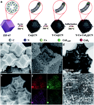 | ||
| Fig. 1 (a) Schematic illustration of the synthesis process of Y-Co–CoSx@CN. (b and c) SEM, (d) TEM, (e) HAADF-STEM, (f) EDX mapping, and (g) HRTEM images of Y-Co–CoSx@CN. | ||
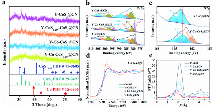
Finally, Y-Co@CN was converted into Y-Co–CoS1.097–CoS2@CN (denoted as Y-Co–CoSx@CN) by partial sulfuration of Co@CN, using thiourea as the S source. In Fig. 2a, the XRD results show that with an increase in the mass ratio of thiourea to Co@CN from 2/1 to 4/1, the Co NPs are gradually transformed into Co–CoSx NPs, and then CoS2 NPs. TEM images (Fig. 1b–d) display that Y-Co–CoSx@CN (mthiourea/mCo@CN = 2![[thin space (1/6-em)]](https://www.rsc.org/images/entities/char_2009.gif) :
:![[thin space (1/6-em)]](https://www.rsc.org/images/entities/char_2009.gif) 1) well preserves the morphology of the yolk–shell rhombic dodecahedron. The high-angle annular dark-field scanning TEM (HAADF-STEM) image and elemental mapping image of Y-Co–CoSx@CN clearly reveal the uniform distribution of Co, S, N, and O elements (Fig. 1e and f). A close inspection of nanoparticles shows the d-spacings of lattice fringes of 0.206, 0.252, and 0.277 nm, corresponding to the Co (111), CoS1.097 (220), and CoS2 (200) planes (Fig. 1g), respectively, confirming the formation of a heterojunction in Y-Co–CoSx@CN. The contents of Co, S, N, and C elements in Co–CoSx@CN are listed in Table S1.† The main compositions of Y-Co–CoSx@CN are Co, CoS1.097, CoS2, and N-doped C. The specific surface area of Y-Co–CoSx@CN (74 m2 g−1) is relatively low as compared with that of Y-Co@CN (300 m2 g−1), which could be attributed to the pore occupation by Sx2− in the sulfurization process (Fig. S5 and S6†). For comparison, Co–CoSx@CN with different structures and their corresponding precursors were also prepared and characterized (Scheme S1, Fig. S2, S3 and S7–S10†).
1) well preserves the morphology of the yolk–shell rhombic dodecahedron. The high-angle annular dark-field scanning TEM (HAADF-STEM) image and elemental mapping image of Y-Co–CoSx@CN clearly reveal the uniform distribution of Co, S, N, and O elements (Fig. 1e and f). A close inspection of nanoparticles shows the d-spacings of lattice fringes of 0.206, 0.252, and 0.277 nm, corresponding to the Co (111), CoS1.097 (220), and CoS2 (200) planes (Fig. 1g), respectively, confirming the formation of a heterojunction in Y-Co–CoSx@CN. The contents of Co, S, N, and C elements in Co–CoSx@CN are listed in Table S1.† The main compositions of Y-Co–CoSx@CN are Co, CoS1.097, CoS2, and N-doped C. The specific surface area of Y-Co–CoSx@CN (74 m2 g−1) is relatively low as compared with that of Y-Co@CN (300 m2 g−1), which could be attributed to the pore occupation by Sx2− in the sulfurization process (Fig. S5 and S6†). For comparison, Co–CoSx@CN with different structures and their corresponding precursors were also prepared and characterized (Scheme S1, Fig. S2, S3 and S7–S10†).
In the Co 2p3/2 XPS spectrum of Y-Co–CoSx@CN, the peaks at 778.9, 780.7, and 783.4 eV are assigned to Co0, Co3+, and Co2+, respectively (Fig. 2b). In the S 2p XPS spectrum of Y-Co–CoSx@CN, the peaks at 161.0 and 161.8 eV are ascribed to Co–S groups, while those at 162.4 and 163.2 eV are attributed to S–S bonds (S22−) (Fig. 2c).38 These results confirm the co-existence of Co and CoSx in Y-Co–CoSx@CN, in agreement with the TEM and XRD results. The peaks at 778.9 (Co0) and 783.4 eV (Co2+) for Y-Co–CoSx@CN exhibit a positive or negative shift of 0.3 or 0.9 eV as compared with those for Y-Co@CN (778.6 eV) or Y-CoS2@CN (784.3 eV), respectively. The S22− peaks of Y-Co–CoSx@CN show a negative shift of 1.2 eV as compared with those of Y-CoS2@CN. Collectively, there truly exist electronic interactions between the Co and CoSx NPs in Y-Co–CoSx@CN.
The electronic structures and coordination environment of the Co species were investigated by X-ray absorption fine structure spectroscopy (XAFS) measurements. The X-ray absorption near edge structure (XANES) spectra of the Co K-edge for Co foil, Y-Co@CN, Y-Co–CoSx@CN, and Y-CoS2@CN are shown in Fig. 2d. The pre-edge position of Y-Co–CoSx@CN is located between those of Y-Co@CN and Y-CoS2@CN, indicating that the valence state of Co is situated between 0 and +2.39,40 The EXAFS spectra of Y-Co–CoSx@CN (Fig. 2e and S11†) and the fitting results reveal that the peaks at 2.06 and 2.25 Å correspond to the contributions of Co-S1 and Co-S2, respectively, due to the coexistence of CoS1.097 and CoS2 (Fig. S11† and Table S2†).41 The peak located at 2.42 Å may be ascribed to the contribution of Co–Co with a coordination number of 4.5. All of these characterization results elucidate that the Co–CoSx heterojunction has been successfully fabricated.
2.2 HMF electro-oxidation performance
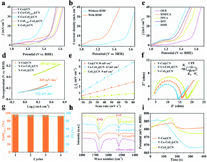
The electro-catalytic performances of the as-prepared materials in HMF oxidation were investigated by using a three-electrode system in an H-type electrolysis cell. Linear sweep voltammograms (LSV) of the electrodes with 5 mM HMF were measured in 0.1 M KOH electrolytes. As shown in Fig. S12,† the LSV curves of Y-Co@C-T and Co@CN with different structures show poor electro-catalytic activities with high potentials (>1.50 V) for HMF oxidation at 10 mA cm−2 current density. The partial sulfuration of Co gives rise to an enhancement in the electro-catalytic activity (Fig. 3a). Particularly, when the mass ratio of thiourea to Co@CN is 2, only a potential of 1.29 V vs. RHE is required for Y-Co–CoSx@CN to reach a current density of 10 mA cm−2 for HMF oxidation, which is superior to that of all the electrocatalysts reported previously in 0.1 M KOH electrolytes (Table S3†). Further increasing mthiourea/mCo@CN (Y-CoSx@CN and Y-CoS2@CN) leads to a decline in electro-catalytic performance, as a result of the absence of Co–CoSx heterojunctions.In the case of Y-Co–CoSx@CN, the potential at the same current density is shifted to 1.56 V vs. RHE for the OER without the addition of 5 mM HMF in the electrolyte (Fig. 3b). Besides, as compared with the OER, Y-Co–CoSx@CN affords much lower onset potentials and higher current densities in the presence of any intermediate products (Fig. 3c), including 5-hydroxymethyl-2-furancarboxylic acid (HMFCA), 2-formyl-5-furancarboxylic acid (FFCA), and 2,5-diformylfuran (DFF). These results suggest that the electro-oxidation of HMF to FDCA on Y-Co–CoSx@CN is a preferential reaction at lower applied potentials, which could also be observed on Y-Co@CN and Y-CoS2@CN (Fig. S13†). Moreover, Y-Co–CoSx@CN exhibits superior electro-catalytic performance to Co–CoSx@CN, H-Co–CoSx@CN, and D-Co–CoSx@CN under identical conditions (Fig. S14†). This result suggests that the construction of the yolk–shell structure contributes to the enhancement of electro-catalytic activity, which might be ascribed to the fact that a higher surface area could provide more exposed active sites (Fig. S10b†).
The Tafel plot was used to analyze the intrinsic activity of the catalysts in the presence of HMF (Fig. 3d). Y-Co–CoSx@CN exhibits a much lower Tafel slope (152 mV dec−1) as compared with Y-Co@CN (245 mV dec−1) and Y-CoSx@CN (335 mV dec−1), indicative of its favorable HMFOR kinetics. Cyclic voltammetry (CV) curves at different scan rates were measured in a non-faradaic region of 0.53–0.65 V vs. RHE to evaluate the double-layer capacitance (Cdl) that is proportional to the electrochemical surface area (ECSA) (Fig. S15†). In Fig. 3e, Y-Co–CoSx@CN (63 mF cm−2) shows a much higher Cdl value than those of Y-Co@CN (30 mF cm−2) and Y-CoS2@CN (9 mF cm−2), demonstrating that Y-Co–CoSx@CN possesses more active sites for HMF oxidation. Electrochemical impedance spectroscopy (EIS) analysis was performed to estimate the conductivity between electrodes and the electrolyte. As shown in Fig. 3f, Y-Co–CoSx@CN presents a much smaller Rct value of 9.1 Ω as compared with Y-Co@CN (11.3 Ω) and Y-CoSx@CN (10.5 Ω), implying a much faster electron transfer. The excellent electro-catalytic performance of Y-Co–CoSx@CN for the HMFOR may be ascribed to the combined characteristics including favorable HMFOR kinetics, abundant active sites, and accelerated electron transport.
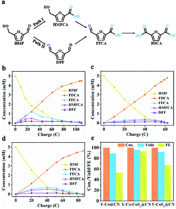
The potentiostatic electrolysis of HMF electrooxidation on Y-Co–CoSx@CN was performed in a divided cell at 1.40 V (vs. RHE) to quantify the contents of oxidation products and calculate the faradaic efficiencies (FE). There are two possible reaction pathways of HMF oxidation to FDCA (Fig. 4a), in which HMFCA or DFF as key intermediates produced from the initial aldehyde or alcohol oxidation, respectively, could be transformed into FFCA and finally into FDCA. Six electrons are transferred in the conversion processes. Thus, 58C charges are required for the total transformation of HMF (5 mM) into FDCA. With an increase in the electrolysis time, the content of FDCA is increased gradually at the expense of HMF (Fig. S16†). The applied potential is kept constant, however, the current density would gradually decrease (Fig. S16a†) due to the fact that the concentration of HMF could not remain constant during the reaction. As shown in Fig. 4b–d, the HMFCA and FFCA intermediates are identified, while a negligible amount of DFF is detected, demonstrating that Path I is dominant in the HMFOR. As shown in Fig. 4e, Y-Co–CoSx@CN furnishes a FDCA yield of ca. 96.0% and faradaic efficiency (FE) of ca. 93.5% (the electrolysis time is 5 h), both of which are much higher than those of Y-CoSx@CN (FDCA yield of 92.0% and FE of 67.5%) and Y-Co@CN (FDCA yield of 89.5% and FE of 53.2%). Moreover, we also investigated the influence of the HMF concentration on the yield and FE of the product. As shown in Fig. S16c and d,† when the potentiostatic electrolysis of HMF (50 mM) electrooxidation was performed, Y-Co–CoSx@CN affords a FDCA yield of ca. 64.8% and faradaic efficiency (FE) of ca. 80.5%, both of which are lower than that obtained in the potentiostatic electrolysis of HMF (5 mM) oxidation.
The stability of Y-Co–CoSx@CN was also investigated under continuous potentiostatic electrolysis for four consecutive cycles. The FDCA yield remains around 92.8%, and the FE remains above 90% (Fig. 3g). The TEM images (Fig. S17a†) of the reused Co–CoSx@CN catalyst display the well-preserved yolk–shell structure without obvious aggregation of Co–CoSx NPs. In the XPS spectra, Y-Co–CoSx@CN still maintains the original phases but with minor changes in the content of ingredients (Fig. S17b and c†). All of these observations suggest that Y-Co–CoSx@CN exhibits good durability in the HMFOR.
2.3 Construction of other heterojunctions for the HMFOR
We also extended our strategy to the preparation of Y-Co–CoP@CN with the Co–CoP heterojunction. As shown in Fig. S18–S20,† all the results of XRD, TEM, HRTEM, HAAD-STEM, Raman spectroscopy, and XPS collectively illustrate the successful synthesis of Y-Co–CoP@CN with the Co–CoP heterojunction. As shown in Fig. S21,† the Y-Co–CoP@CN electrode exhibits an overpotential of 0.19 or 0.31 V to reach a current density of 10 mA cm−2 in 0.1 M KOH with or without 5 mM HMF, respectively. As expected, the overpotential of Y-Co–CoP@CN (0.19 V) is lower than those of Y-Co@CN (0.28 V) and Y-CoP@CN (0.22 V) (Fig. S21 and S22†). All of the above results demonstrate that the construction of heterojunctions plays an important role in optimizing the physicochemical properties, which are crucial to the high-performance HMFOR.2.4 DFT calculations
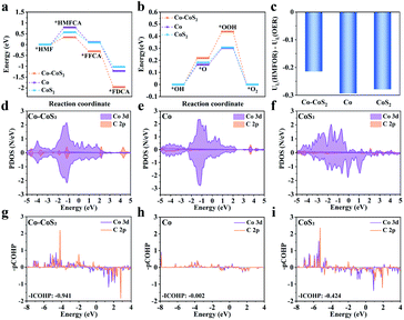
Theoretical calculations were carried out on the Co–CoS2, Co, and CoS2 models, in order to clarify their differences in both catalytic activity and product selectivity for the HMFOR (Fig. S23–S26†). For simplicity, the CoS2 model represents CoSx in the Co–CoSx heterojunction. According to the electro-catalytic performance results, the reaction pathway HMF → HMFCA → FFCA → FDCA is predominant in the HMFOR (Fig. 4a). In the three elementary reactions, the first one (i.e., *HMF chemisorption) of the HMFOR is endothermic, acting as the rate-determining step (RDS). Specially, the free-energy change of HMF → HMFCA on Co–CoS2 (0.34 eV) is lower than those on Co (0.79 eV) and CoS2 (0.57 eV). Besides, the produced *FFCA intermediate on Co–CoS2 could also be readily transformed into *FDCA with a high exothermicity (Fig. 5a). Furthermore, Co–CoS2 shows the highest free-energy change in the OER process (Fig. 5b). These results demonstrate that the Co–CoS2 heterojunction shows a favorable energy input for the overall HMFOR.The OER is proposed to be the main competitive reaction against the HMFOR. The difference between the limiting potentials for the HMFOR and OER (i.e., UL(HMFOR) − UL(OER)) could quantitatively assess the selectivity of Co–CoS2, Co, and CoS2 (Fig. 5c). The UL(HMFOR) − UL(HER) value (−0.21 V) for Co–CoS2 is more positive than that for Co (−0.29 V) and CoS2 (−0.28 V), suggesting that the competing OER is suppressed over Co–CoS2 to afford a higher selectivity toward the HMFOR.
To further investigate the different electro-catalytic behaviors of catalysts, the partial density of states (PDOS) and projected crystal orbital Hamilton population (pCOHP) were determined to evaluate the interactions between the adsorbed HMF and catalysts (Fig. 5d–i). Compared with Co and CoS2, more PDOSs of Co 3d in Co–CoS2 are involved in the overlapping region with those of C 2p near the Fermi level. Correspondingly, a more negative ICOHP value is obtained on Co–CoS2. These results indicate that Co–CoS2 exhibits a strong ability for HMF adsorption, due to the favorable d–p coupling. Moreover, the charge density differences and Bader charge analysis demonstrate that charge shift from Co–CoS2 to *HMF is 0.20 e, which is higher than those from Co (0.06 e) and CoS2 (0.16 e), further suggesting the strong interaction between HMF and Co–CoS2 (Fig. 6a–c). Furthermore, FT-IR and open circuit potential (OCP) experiments were carried out to further investigate the HMF adsorption strength on the catalysts. As shown in Fig. 3h, two strong bands at 1674 and 1523 cm−1 for pure HMF are observed, attributed to the stretching vibration of the C![[double bond, length as m-dash]](https://www.rsc.org/images/entities/char_e001.gif) O bond (vC
O bond (vC![[double bond, length as m-dash]](https://www.rsc.org/images/entities/char_e001.gif) O) of the aldehyde group and C
O) of the aldehyde group and C![[double bond, length as m-dash]](https://www.rsc.org/images/entities/char_e001.gif) C bond (vC
C bond (vC![[double bond, length as m-dash]](https://www.rsc.org/images/entities/char_e001.gif) C) of the furan ring.42,43 When the catalysts are subjected to the adsorption of HMF, Y-Co–CoSx@CN (9.5 cm−1) shows much larger red-shift in the C
C) of the furan ring.42,43 When the catalysts are subjected to the adsorption of HMF, Y-Co–CoSx@CN (9.5 cm−1) shows much larger red-shift in the C![[double bond, length as m-dash]](https://www.rsc.org/images/entities/char_e001.gif) O bond than Y-Co@CN (3.0 cm−1) and Y-CoSx@CN (3.7 cm−1), suggesting the strongest chemical adsorption of HMF on Y-Co–CoSx@CN. As shown in Fig. 3i, the OCP of Y-Co–CoSx@CN is decreased significantly by ca. 17 mV, in comparison with the decreased 4 and 10 mV for Y-Co@CN and Y-CoSx@CN, respectively, indicating the strongest adsorption of HMF on the surface of heterojunction catalysts.44
O bond than Y-Co@CN (3.0 cm−1) and Y-CoSx@CN (3.7 cm−1), suggesting the strongest chemical adsorption of HMF on Y-Co–CoSx@CN. As shown in Fig. 3i, the OCP of Y-Co–CoSx@CN is decreased significantly by ca. 17 mV, in comparison with the decreased 4 and 10 mV for Y-Co@CN and Y-CoSx@CN, respectively, indicating the strongest adsorption of HMF on the surface of heterojunction catalysts.44
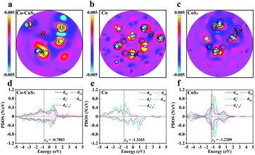 | ||
| Fig. 6 (a–c) Charge density differences for the adsorption of HMF on Co–CoS2, Co, and CoS2, and (d–f) a detailed PDOS of the Co d orbitals in Co–CoS2, Co, and CoS2. | ||
To gain insight into the origin of the interactions between catalysts and adsorbates, a detailed PDOS for the Co d orbitals in Co–CoS2, Co, and CoS2 was analyzed. As shown in Fig. 6d–f, compared with Co and CoS2, the construction of the Co–CoS2 heterojunction induces the asymmetric arrangement of d orbital electrons in the spin channels, indicative of the spin polarization. The intensified spin polarization in Co–CoS2 makes their electronic states move to the Fermi level, thus enhancing their capability in the adsorption of reactants/intermediates. Also, the COHP analysis of Co–CoS2 discloses that dxy, dx2−y2, 3dxz, and dz2 orbitals mainly participate in the Co–C molecular orbitals (Table S4†).
3 Conclusions
In summary, heterojunctions embedded in yolk–shell polyhedroa assembled from N-doped carbon nanotubes are fabricated by employing ZIF-67 as the precursor through a controlled pyrolysis strategy. The as-synthesized Y-Co–CoSx@CN exhibits superior electro-catalytic performances at a low potential (η10 = 1.29 vs. RHE) in 0.1 M KOH with 5 mM HMF, affording a FDCA yield of 96.0% and FE of 93.5%. DFT calculations reveal that the construction of Co–CoSx heterojunction induces the asymmetric arrangement of d orbital electrons in the spin channels, giving rise to the spin polarization. The intensified spin polarization in Co–CoSx makes their electronic states move to the Fermi level, thus improving their capability in the adsorption of reactants/intermediates. The effective d–p couplings between catalysts and reactants/intermediates are responsible for the lower activation energy in the rate-determining step, contributing to a favorable energy input for the overall HMFOR. Consequently, the electric polarization could be a sensitive descriptor in determining the HMFOR performance.Author contributions
Jianmin Chen synthesized the materials, carried out most of the structural characterization and catalytic tests, and cowrote the paper. Mingjun Zhou carried out catalytic tests. Yajing Wang performed the DFT calculations, and cowrote the paper. Yingwei Li conceived the idea and cowrote the paper. All authors discussed the results and commented on the manuscript.Conflicts of interest
There are no conflicts to declare.Acknowledgements
This work was supported by the National Natural Science Foundation of China (21825802, 22138003, and 22008075), the Fundamental Research Funds for the Central Universities (2020ZYGXZR008), the Foundation of Advanced Catalytic Engineering Research Center of the Ministry of Education (2020AC006), the Natural Science Foundation of Guangdong Province (2017A030312005, and 2021A1515010126), and the Science and Technology Program of Guangzhou (202102020651).Notes and references
- C. Xu, E. Paone, D. Rodríguez-Padrón, R. Luque and F. Mauriello, Chem. Soc. Rev., 2020, 49, 4273 RSC.
- X. Deng, G. Y. Xu, Y. J. Zhang, L. Wang, J. Zhang, J. F. Li, X. Z. Fu and J. L. Luo, Angew. Chem., Int. Ed., 2021, 60, 20535 CrossRef CAS PubMed.
- S. Li, X. Sun, Z. Yao, X. Zhong, Y. Cao, Y. Liang, Z. Wei, S. Deng, G. Zhuang, X. Li and J. Wang, Adv. Funct. Mater., 2019, 29, 1904780 CrossRef CAS.
- R. J. van Putten, J. C. van der Waal, E. de Jong, C. B. Rasrendra, H. J. Heeres and J. G. de Vries, Chem. Rev., 2013, 113, 1499 CrossRef CAS PubMed.
- K. A. P. Payne, S. A. Marshall, K. Fisher, M. J. Cliff, D. M. Cannas, C. Yan, D. J. Heyes, D. A. Parker, I. Larrosa and D. Leys, ACS Catal., 2019, 9, 2854 CrossRef CAS PubMed.
- A. H. Motagamwala, W. Won, C. Sener, D. M. Alonso, C. T. Maravelias and J. A. Dumesic, Sci. Adv., 2018, 4, eaap9722 CrossRef PubMed.
- A. R. Poerwoprajitno, L. Gloag, J. Watt, S. Cychy, S. Cheong, P. V. Kumar, T. M. Benedetti, C. Deng, K. H. Wu, C. E. Marjo, D. L. Huber, M. Muhler, J. Justin Gooding, W. Schuhmann, D. W. Wang and R. D. Tilley, Angew. Chem., Int. Ed., 2020, 59, 15487 CrossRef CAS PubMed.
- Y. Zhao, M. Cai, J. Xian, Y. Sun and G. Li, J. Mater. Chem. A, 2021, 9, 20164 RSC.
- Y. Yang and T. Mu, Green Chem., 2021, 23, 4228 RSC.
- G. Yang, Y. Jiao, H. Yan, Y. Xie, A. Wu, X. Dong, D. Guo, C. Tian and H. Fu, Adv. Mater., 2020, 32, 2000455 CrossRef CAS PubMed.
- S. Li, X. Sun, Z. Yao, X. Zhong, Y. Cao, Y. Liang, Z. Wei, S. Deng, G. Zhuang, X. Li and J. Wang, Adv. Funct. Mater., 2019, 29, 1904780 CrossRef CAS.
- B. Zhou, Y. Li, Y. Zou, W. Chen, W. Zhou, M. Song, Y. Wu, Y. Lu, J. Liu, Y. Wang and S. Wang, Angew. Chem., Int. Ed., 2021, 60, 22908 CrossRef CAS PubMed.
- K. Gu, D. Wang, C. Xie, T. Wang, G. Huang, Y. Liu, Y. Zou, L. Tao and S. Wang, Angew. Chem., Int. Ed., 2021, 60, 20253 CrossRef CAS PubMed.
- M. Park, M. Gu and B. S. Kim, ACS Nano, 2020, 14, 6812 CrossRef CAS PubMed.
- Y. Song, Z. Li, K. Fan, Z. Ren, W. Xie, Y. Yang, M. Shao and M. Wei, Appl. Catal., B, 2021, 299, 120669 CrossRef CAS.
- X. J. Bai, W. X. He, X. Y. Lu, Y. Fu and W. Qi, J. Mater. Chem. A, 2021, 9, 14270–14275 RSC.
- M. Cai, Y. Zhang, Y. Zhao, Q. Liu, Y. Li and G. Li, J. Mater. Chem. A, 2020, 8, 20386 RSC.
- X. Lu, K. H. Wu, B. Zhang, J. Chen, F. Li, B. J. Su, P. Yan, J. M. Chen and W. Qi, Angew. Chem., Int. Ed., 2021, 60, 14528 CrossRef CAS PubMed.
- D. H. Nam, B. J. Taitt and K. S. Choi, ACS Catal., 2018, 8, 1197 CrossRef CAS.
- B. You, N. Jiang, X. Liu and Y. Sun, Angew. Chem., Int. Ed., 2016, 55, 9913 CrossRef CAS PubMed.
- N. Jiang, B. You, R. Boonstra, I. M. Terrero Rodriguez and Y. Sun, ACS Energy Lett., 2016, 1, 386 CrossRef CAS.
- B. You, X. Liu, N. Jiang and Y. Sun, J. Am. Chem. Soc., 2016, 138, 13639 CrossRef CAS PubMed.
- M. J. Kang, H. Park, J. Jegal, S. Y. Hwang, Y. S. Kang and H. G. Cha, Appl. Catal., B, 2019, 242, 85 CrossRef CAS.
- Y. Lu, C. L. Dong, Y. C. Huang, Y. Zou, Z. Liu, Y. Liu, Y. Li, N. He, J. Shi and S. Wang, Angew. Chem., Int. Ed., 2020, 59, 19215 CrossRef CAS PubMed.
- J. N. Hausmann, R. Beltrán-Suito, S. Mebs, V. Hlukhyy, T. F. Fässler, H. Dau, M. Driess and P. W. Menezes, Adv. Mater., 2021, 33, 2008823 CrossRef CAS PubMed.
- W. J. Liu, L. Dang, Z. Xu, H. Q. Yu, S. Jin and G. W. Huber, ACS Catal., 2018, 8, 5533 CrossRef CAS.
- M. Zhang, Y. Liu, B. Liu, Z. Chen, H. Xu and K. Yan, ACS Catal., 2020, 10, 5179 CrossRef CAS.
- Y. Xie, Z. Zhou, N. Yang and G. Zhao, Adv. Funct. Mater., 2021, 31, 2102886 CrossRef CAS.
- B. J. Taitt, D. H. Nam and K. S. Choi, ACS Catal., 2019, 9, 660 CrossRef CAS.
- N. Zhang, Y. Zou, L. Tao, W. Chen, L. Zhou, Z. Liu, B. Zhou, G. Huang, H. Lin and S. Wang, Angew. Chem., Int. Ed., 2019, 58, 15895 CrossRef CAS PubMed.
- S. Liang, L. Pan, T. Thomas, B. Zhu, C. Chen, J. Zhang, H. Shen, J. Liu and M. Yang, Chem. Eng. J., 2021, 415, 128864 CrossRef CAS.
- Y. Lu, C. L. Dong, Y. C. Huang, Y. Zou, Y. Liu, Y. Li, N. Zhang, W. Chen, L. Zhou, H. Lin and S. Wang, Sci. China: Chem., 2020, 63, 980 CrossRef CAS.
- Y. Lu, T. Liu, C. L. Dong, Y. C. Huang, Y. Li, J. Chen, Y. Zou and S. Wang, Adv. Mater., 2021, 33, 2007056 CrossRef CAS PubMed.
- L. Ju, X. Tan, X. Mao, Y. Gu, S. Smith, A. Du, Z. Chen, C. Chen and L. Kou, Nat. Commun., 2021, 12, 1 CrossRef PubMed.
- J. Wang, M. Zhang, G. Yang, W. Song, W. Zhong, X. Wang, M. Wang, T. Sun and Y. Tang, Adv. Funct. Mater., 2021, 31, 2101532 CrossRef CAS.
- Z. Li, M. Hu, P. Wang, J. Liu, J. Yao and C. Li, Coord. Chem. Rev., 2021, 439, 213953 CrossRef CAS.
- Q. Liang, J. Chen, F. Wang and Y. Li, Coord. Chem. Rev., 2020, 424, 213488 CrossRef CAS.
- Y. Li, J. Yin, L. An, M. Lu, K. Sun, Y. Q. Zhao, D. Gao, F. Cheng and P. Xi, Small, 2018, 14, 1801070 CrossRef PubMed.
- D. Cao, D. Liu, S. Chen, O. A. Moses, X. Chen, W. Xu, C. Wu, L. Zheng, S. Chu, H. Jiang, C. Wang, B. Ge, X. Wu, J. Zhang and L. Song, Energy Environ. Sci., 2021, 14, 906 RSC.
- J. Hao, W. Luo, W. Yang, L. Li and W. Shi, J. Mater. Chem. A, 2020, 8, 22694 RSC.
- T. Kadono, T. Kubota, I. Hiromitsu and Y. Okamoto, Appl. Catal., A, 2006, 312, 125 CrossRef CAS.
- X. Huang, J. Song, M. Hua, Z. Xie, S. Liu, T. Wu, G. Yang and B. Han, Green Chem., 2020, 22, 843 RSC.
- L. Gao, Z. Liu, J. Ma, L. Zhong, Z. Song, J. Xu, S. Gan, D. Han and L. Niu, Appl. Catal., B, 2020, 261, 118235 CrossRef.
- W. D. Zhang, Q. T. Hu, L. L. Wang, J. Gao, H. Y. Zhu, X. Yan and Z. G. Gu, Appl. Catal., B, 2021, 286, 119906 CrossRef CAS.
Footnote |
| † Electronic supplementary information (ESI) available. See DOI: 10.1039/d2sc00038e |
| This journal is © The Royal Society of Chemistry 2022 |

