 Open Access Article
Zwitterionic iodonium species afford halogen bond-based porous organic frameworks†
Natalia S.
Soldatova
 a,
Pavel S.
Postnikov
 *ab,
Daniil M.
Ivanov
ac,
Oleg V.
Semyonov
a,
Olga S.
Kukurina
a,
Olga
Guselnikova
 ad,
Yusuke
Yamauchi
 de,
Thomas
Wirth
 f,
Viktor V.
Zhdankin
 g,
Mekhman S.
Yusubov
a,
Rosa M.
Gomila
 h,
Antonio
Frontera
 i,
Giuseppe
Resnati
 *aj and
Vadim Yu.
Kukushkin
 *c
*c
aResearch School of Chemistry and Applied Biomedical Sciences, Tomsk Polytechnic University, Tomsk 634034, Russian Federation. E-mail: postnikov@tpu.ru
bDepartment of Solid State Engineering, Institute of Chemical Technology, Prague 16628, Czech Republic
cInstitute of Chemistry, Saint Petersburg State University, Saint Petersburg 199034, Russian Federation. E-mail: v.kukushkin@spbu.ru
dJST-ERATO Yamauchi Materials Space-Tectonics Project, National Institute for Materials Science (NIMS), 1-1 Namiki, Tsukuba, Ibaraki 305-0044, Japan
eAustralian Institute for Bioengineering and Nanotechnology (AIBN), The University of Queensland, Brisbane, QLD 4072, Australia
fSchool of Chemistry, Cardiff University, Park Place, Cardiff, UK
gDepartment of Chemistry and Biochemistry, University of Minnesota, Duluth, MN 55812, USA
hServeis Científico-Tècnics, Universitat de les Illes Balears, Crta. de Valldemossa Km 7.5, 07122 Palma de Mallorca, Spain
iDepartament de Química, Universitat de les Illes Balears, Crta. de Valldemossa Km 7.5, 07122 Palma de Mallorca, Spain
jNFMLab, Department of Chemistry, Materials and Chemical Engineering “Giulio Natta”; Politecnico di Milano, via Mancinelli 7, I-20131 Milano, Italy. E-mail: giuseppe.resnati@polimi.it
First published on 12th April 2022
Abstract
Porous architectures characterized by parallel channels arranged in honeycomb or rectangular patterns are identified in two polymorphic crystals of a zwitterionic 4-(aryliodonio)-benzenesulfonate. The channels are filled with disordered water molecules which can be reversibly removed on heating. Consistent with the remarkable strength and directionality of the halogen bonds (XBs) driving the crystal packing formation, the porous structure is stable and fully preserved on almost quantitative removal and readsorption of water. The porous systems described here are the first reported cases of one-component 3D organic frameworks whose assembly is driven by XB only (XOFs). These systems are a proof of concept for the ability of zwitterionic aryliodonium tectons in affording robust one-component 3D XOFs. The high directionality and strength of the XBs formed by these zwitterions and the geometrical constraints resulting from the tendency of their hypervalent iodine atoms to act as bidentate XB donors might be key factors in determining this ability.
Introduction
Metal organic frameworks (MOFs) and covalent organic frameworks (COFs) play a significant role in science and technology. Such systems are widely applied in gas storage and separation,1–7 capture of hazardous compounds (e.g., heavy metals, pesticides, and volatile organic compounds),8–12 catalysis,13–17etc. The approaches for the preparation of these systems include the interaction between structurally defined building blocks with the formation of coordination (MOFs) or covalent (COFs) bonds.Very recently, the modern palette of porous materials has been enriched by novel systems wherein the structural units are assembled via relatively weak interactions, with supramolecular organic frameworks18–20 (SOFs) and hydrogen-bonded organic frameworks21–26 (HOFs) being the most common representatives. However, the development of these materials is challenging as a consequence of the lower directionality of weak noncovalent bonds in comparison to coordination or covalent bonds affording MOFs and COFs.27,28 In this context, halogen bonding (XB) is becoming a novel tool for the controlled assembly of molecular tectons into highly ordered frameworks29,30 and is here employed for the obtainment of 3D and one-component purely halogen-bonded organic frameworks (XOFs). It was considered that the high directionality of the interaction might act as an advantage of the approach. Notably, a one-component 2D XOF was observed in crystals of tetrabromobenzene-1,4-dicarboxylic acid.30
Among the wealth of porous molecular crystals wherein XB contributes to sustaining the architecture, only two examples that can be considered as 3D XOFs were obtained via (i) cocrystallization of the tetrahedral pyridine-based XB acceptor and 1,3,4,5-tetraiododifluorobenzene to form a di-component XOF29 and (ii) assembly of a heterotopic tecton to give an unstable 3D XOF.31
The well-developed strategy of assembly of XB donors with nitrogen-based XB acceptors furnishes,32,33 in particular, halogen-bonded 3D structures (exhibiting diamondoid-like cage entities), which are promising porous materials; these structures have not been tested as adsorbents.34–38 In some other cases, assembly of iodine species with N-based XB acceptors provided 2D or 1D architectures, featuring cavities.29,39–41
Other reported examples of XB-assembled SOFs are built by the simultaneous action of XB and hydrogen bonding (HB).42,43
Diaryliodonium salts44,45 can function as useful building blocks in supramolecular chemistry46 due to their ability to form discrete adducts and 1D chains or ribbons.47–50 The iodine typically functions as a bidentate XB donor51–56 and the XB acceptor is, by far in most cases, the anion. Despite the wide applicability of iodonium salts as halogen bond donors in catalysis,54–57 the formation of 3D structures with well-defined pores is still unknown. Among other iodonium salts, the zwitterionic compounds can be promising for the directed design of 3D networks due to the presence of two binding sites. Nevertheless, the number of zwitterionic systems characterized via single-crystal X-ray diffractometry (XRD) is too small to enable statistically meaningful statements, but it is interesting to observe that although 1D chains and ribbons58–62 are the most common halogen-bonded systems formed by these iodonium salts, the tendency to form multidimensional nets, e.g., 2D59,63 networks, seems definitely higher than when starting from diaryliodonium salts wherein the positive and negative sites are in different molecular entities.
We decided to verify whether zwitterionic iodonium species can indeed function as promising tectons for the reliable design and synthesis of multidimensional supramolecular architectures in general and new XOFs in particular. In this study, we synthesized novel zwitterionic 4-(aryliodonio)benzene-sulfonate species (Scheme 1) and we report that crystallization of one of them leads to porous XOFs. We reasoned that the strong electrostatic attraction between the cationic and anionic sites in the zwitterion may act synergistically with the remarkable directionality of the XB and enable the self-assembly of robust XOFs. The design and preparation of XOFs based on zwitterionic iodonium salts may thus represent a new opportunity in the challenging and rewarding field of novel porous organic materials. Density functional theory (DFT) calculations provide an insight into the relative intensity of both σ-holes located at the extensions of both C–I bonds and the energetic features associated with the XBs.
 | ||
| Scheme 1 Synthesis of zwitterionic iodonium salts 1 (Ar = 2,4,6-Me3C6H2; 74%), 2 (2,5-Me2C6H3; 60%), and 3 (4-ClC6H4; 98%). | ||
Results and discussion
Halogen bonding and crystal packing in 4-(aryliodonio)-benzenesulfonates
4-Iodobenzenesulfonic acid was used as the starting material for preparing zwitterionic tectons for obtaining XOFs. Iodonium salts 1–3 were synthesized oxidizing this compound with Oxone®/H2SO4 (ref. 49 and 64–68) and coupling it with mesitylene, 1,4-dimethylbenzene, and chlorobenzene (Scheme 1 and Section S1†). On crystallization of 1 from MeOH![[thin space (1/6-em)]](https://www.rsc.org/images/entities/char_2009.gif) :
:![[thin space (1/6-em)]](https://www.rsc.org/images/entities/char_2009.gif) H2O mixtures, two different crystal forms 1a and 1b were obtained depending on the water content: 15
H2O mixtures, two different crystal forms 1a and 1b were obtained depending on the water content: 15![[thin space (1/6-em)]](https://www.rsc.org/images/entities/char_2009.gif) :
:![[thin space (1/6-em)]](https://www.rsc.org/images/entities/char_2009.gif) 1 (v/v) afforded 1a, while methanol with >20% H2O afforded 1b. This behavior indicates that for this iodonium species the solvent plays an active role, possibly a templating role, in the crystal construction. Notably, the structures of 2 and 3 exhibit similar 1D-patterns to those in 1b, but only 1b features the porous structure (see later).
1 (v/v) afforded 1a, while methanol with >20% H2O afforded 1b. This behavior indicates that for this iodonium species the solvent plays an active role, possibly a templating role, in the crystal construction. Notably, the structures of 2 and 3 exhibit similar 1D-patterns to those in 1b, but only 1b features the porous structure (see later).
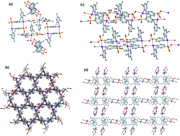
The overall crystal packings of iodonium derivatives 1–3 are quite different from each other, but strict similarities exist in the attractive interactions driving zwitterion binding. Some C–H⋯π and C–H⋯O HBs are present in crystals 1–3 but the overall crystal packing of these systems is controlled by the short, directional, and charge assisted I⋯O XBs (Table 1). Iodine atoms function as bidentate XB donors and sulfonate moieties as bidentate acceptors, with two out of the three sulfonate O atoms acting as monodentate donors of electron density. As typical for XBs, oxygen atoms approach iodine atoms approximately on the extension of C–I covalent bonds. C–I⋯O angles span the range 167–175° but in two interactions involving the disordered sulfonated group in 1b where greater deviations from linearity are observed.
| Compound | C1–I⋯O | d(I⋯O), Å | ∠C1–I⋯O, ° | C7–I⋯O | d(I⋯O), Å | ∠C7–I⋯O, ° |
|---|---|---|---|---|---|---|
| a Probably due to rotation of one sulfonate group of chain 1 around the C–S covalent bond, the oxygen atoms of the corresponding sulfonate group are disordered and have been modeled over two positions; geometric parameters of the XBs associated with the second position are C1–I1⋯O3, d(I⋯O) 2.988(3) Å, ∠C1–I1⋯O3 171.39(7)°; C7B–I1B⋯O1, d(I⋯O) 3.231(3) Å, C7B–I1B⋯O1 149.22(9)°. | ||||||
| 1a | C1–I1⋯O3 | 2.861(4) | 168.39(10) | C7–I1⋯O2 | 2.877(2) | 170.31(10) |
| 1b chain 1 | C1–I1⋯O3D | 3.267(3) | 166.70(8) | C7–I1⋯O1B | 2.8305(16) | 171.08(7) |
| C1B–I1B⋯O3B | 3.0577(18) | 169.14(7) | C7B–I1B⋯O1D | 2.755(3) | 155.97(10) | |
| 1b chain 2 | C1A–I1A⋯O2A | 2.949(2) | 173.56(9) | C7A–I1A⋯O1A | 2.8173(19) | 169.60(6) |
| 2 | C1–I1⋯O2 | 3.007(5) | 171.34(17) | C7–I1⋯O1 | 2.864(4) | 169.41(12) |
| 3 chain 1 | C1–I1⋯O3 | 2.900(4) | 175.07(16) | C7–I1⋯O1 | 2.734(4) | 171.94(16) |
| 3 chain 2 | C1A–I1A⋯O3A | 2.910(4) | 171.90(16) | C7A–I1A⋯O1A | 2.763(4) | 173.24(15) |
The I⋯O distances, typically varying in the range 2.73–3.05 Å, are similar to those in crystalline 2-(aryliodonio)benzene-sulfonates60 and are substantially shorter than the sum of Bondi vdW radii69 (ΣvdW(O + I) is 3.5 Å). Deviations from these most common values are observed once again for interactions involving the disordered sulfonate group in 1b, the I⋯O1 and I⋯O3D distances increasing to 3.231 and 3.267 Å. Interestingly, in 1b, 2, and 3, the C–I⋯O XBs opposite the phenylsulfonyl moiety are 0.1–0.2 Å longer than the C–I⋯O XBs opposite the other aryl group at iodine, despite the σ-holes opposite the former moiety being more positive than those opposite the second one. A possible rationalization is suggested by the modelling of the interactional landscape present in the packings and is discussed later on. In 1a, the difference between the two C–I⋯O separations is negligible and within 3σ.
A halogen-bonded dimer formed on antiparallel pairing of two zwitterions is a common motif present in all crystals 1–3. A similar motif is present also in the zwitterion 4-(CF3SO2NSO2)C6H4IPh.59 These dimers are further connected to each other via XBs and linear ribbons (1D-network) are present in 1b, 2, and 3 (Fig. 1c and S1†). To the best of our knowledge, a similar 1D-net has never been reported for any other zwitterionic iodonium salts.59–61 One ribbon is found in the lattice of 2, while two distinct but very similar ribbons are present in 1b and 3. In 1a, any dimer formed on antiparallel pairing of two zwitterions is halogen-bonded to four other analogous dimers (Fig. 1a) and a 3D network is formed.
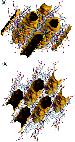
Consistent with the fact that the density of 2 and 3 (1.942 and 2.061 g cm−3, respectively) is much greater than that of 1a and 1b (1.492 and 1.399 g cm−3, respectively), the crystal packings of the former two systems present no voids while the packings of the latter two systems are porous and show parallel channels, along the c and a axes, respectively (Fig. 2). Water is present in these channels but could not be identified through crystallography due to its mobility.
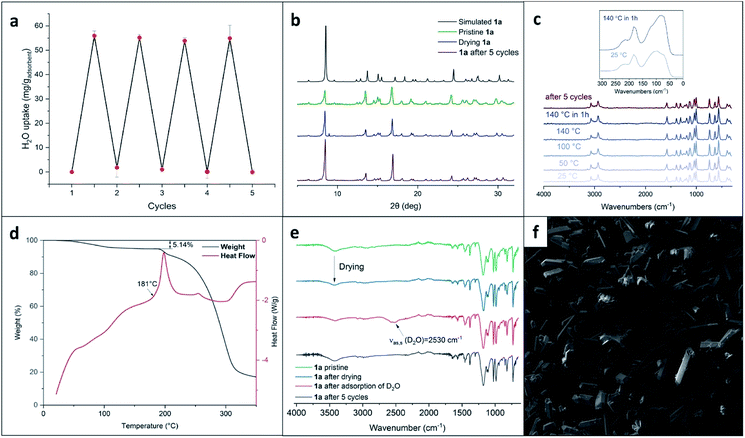
Channels in both crystals have a cylindrical shape with a diameter of ∼10 Å in 1a and ∼12 Å in 1b; the percentage of empty volume is 22.5 in 1a and 25.0 in 1b. Before SQUEEZE in Platon70 was applied, we identified numerous residual peaks, ranging from 1.01 to 2.70 e, in the channel structure of 1a. We believe that the observed residual peaks are related to adsorbed disordered water that was also identified by FTIR and NMR spectroscopy; the NMR spectra of 1a do not exhibit any signals of MeOH. Additional evidence favoring the presence of water was obtained from the IR spectra, where the water peaks were found at 3420 cm−1 (Fig. 3e). Moreover, NMR experiments (residual DMSO in DMSO-d6 was used as an internal standard) clearly demonstrated a lower water content in a dried sample in comparison with the pristine sample and a sample after water adsorption (Fig. S3, ESI†).
Parallel 1D-channels filled with solvent molecules and similar to those found in 1a and 1b have been observed in systems formed on assembly of pyridine based XB acceptors with 1,4-diiodoperfluorobenzene and 1,3,5-triiodoperfluorobenzene.24,52 In 1a, the overall arrangement of the 3D-net adopts a honeycomb-like structure (Fig. 1b) and channels display a hexagonal pattern, while in 1b the 1D-nets assemble in a rectangular geometry (Fig. 1d) which translates into a channel array with analogous topology. In contrast to 1a, the XRD pattern of 1b does not agree with the simulated pattern because of the decomposition occurring on drying (Fig. S2†).
Porosity of the XOF and reversible solvent adsorption/desorption
The results of XRD stimulated us to further investigate the porosity of XOF 1a. We started by assessing the scalability of the preparation (up to 500 mg) of this porous crystal phase. Gram quantities of the XOF were obtained and all batches showed uniform-shaped crystals, as confirmed by powder XRD and SEM images (Fig. 3b and f).Key features for the further harnessing of XOF 1a are its thermal stability and the possibility to remove the solvent while preserving the original crystal structure. The TG/DSC analysis revealed that crystals were stable up to 180 °C, then exothermic decomposition occurred (Fig. 3d). According to the TG data, the prepared XOF 1a can be activated at least at 140 °C without either destruction or phase transition. The initial weight-loss is tentatively associated with the removal of solvent from the voids. To assess the crystal structure preservation on solvent removal, the crystalline powder of 1a was dried for 1.5 hours until the weight of the sample remained constant. The powder XRD study of this batch (Fig. 3b) showed a pattern very similar to that of the pristine material, indicating the original crystal structure.
To verify the functional potential of XOF 1a, we tested the reversibility of water adsorption/desorption from the vapor phase. The weighed sample of dried 1a was placed in a desiccator saturated with water vapor and the weight was monitored. The amount of chemisorbed water was 5.69 mass% (calculated with respect to the mass of the pristine sample of 1a) and this value agrees well with the mass-loss from the pristine powder (5.85 mass%) and mass-loss TG data (Fig. 3d).
The consequence of water adsorption and desorption by crystals of 1a is fully reversible (Fig. 3a). Thus, we conducted a gravimetric determination of the adsorption capacity, along with XRD and spectroscopic monitoring, and found that the structure of 1a is fully preserved after at least 5 cycles of adsorption followed by desorption performed on drying. These experiments indicate that XB stabilizes the XOF crystal structure that is preserved even under relatively harsh conditions of the repeated adsorption and desorption cycles.
We also performed an experiment with the adsorption of D2O (instead of H2O) by the dehydrated sample. The IR-spectra (Fig. 3e) revealed the appearance of νas,s(D2O) stretching at approximately 2530 cm−1 and these data additionally proved the adsorption of D2O from the gas phase by XOF 1a (the assignment of the IR bands is provided in ESI Table S2†).
To get additional data illustrating the stability of XOF 1a, we also carried out variable-temperature Raman spectroscopy experiments. We observed that these spectra remain unchanged even after heating XOF 1a at 140 °C for 1 h (Fig. 3c). The Raman spectrum of 1a, after 5 cycles of water adsorption–desorption, demonstrated the preservation of the crystal structure.
The porous structure of 1a was also studied using nitrogen adsorption–desorption isotherm measurements. Fig. 4a shows a gradual adsorption of nitrogen gas with a small hysteresis loop. The BET surface area of the XOF exhibits an expectedly low value of 17.7 m2 g−1, probably because of the presence of water in the pores. In view of the known difficulties of the Barrett–Joyner–Halenda (BJH) method,71 the pore size distribution curve was obtained by the more accurate Non-Local Density Functional Theory (NLDFT) approach (Fig. 4b). We found that the microporous structure is indeed formed and its total pore volume is 0.017 cm3 g−1. Fig. 4b shows largest pore size of about 7 Å, which corresponds to a cylindrical shaped pore with a diameter of approx. 10 Å; the latter value matches well with our X-ray crystallography data (Fig. 2). Other additional pores (approx. 1.7 nm) were also observed and they correspond to inter-crystallite spaces.
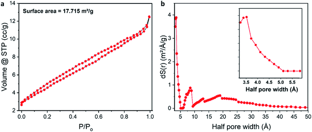 | ||
| Fig. 4 (a) Nitrogen adsorption–desorption isotherm of the XOF; (b) pore size distribution curve obtained by the NLDFT approach (the enlarged image in the range from 3 to 6 Å is shown as an inset). | ||
In the context of the discovery of the stable 3D XOF, it is noteworthy that Uriel and coworkers31 have also employed a heterotopic tecton (featuring two σ-hole donating iodine centers, which are perpendicular to two XB accepting N sites in the same neutral molecule) for the design of XB-based XOFs. The assembly of this tecton led to porous XOFs with empty volumes of 20–24%. The obtained architectures were quite unstable and they irreversibly collapsed even on keeping in air at RT. This instability is believed to be associated31 with the weakness of the XBs involved in the construction of these XOFs. In our study, we generated XOFs of a higher stability and, moreover, we demonstrated the reversibility of water adsorption–desorption associated with these materials. Most likely, the stability is determined by a stronger XB formed between ionic sites of our iodonium zwitterions.
Theoretical study
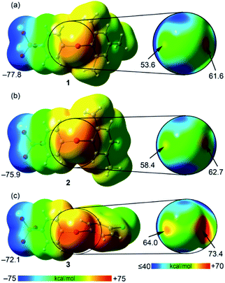
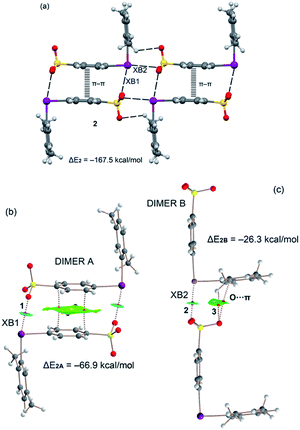
First, the molecular electrostatic potential (MEP) surfaces of compounds 1–3 were computed to study the degree of anisotropic distribution of the electron density around the iodine atom and the MEP energy difference between the two expected σ-holes (Fig. 5). As expected, the MEP values in the three compounds are positive at the iodine atom and negative at the sulfonate group. The MEP minimum is located at the O atoms of the SO3− group with values that range from −77.8 to −72.1 kcal mol−1. The positive MEP embraces the whole iodine atoms, suggesting that the XBs involving these zwitterionic iodonium species can remain attractive even with major deviation from linearity. Nevertheless, the MEP distribution around the iodine atom is anisotropic and two σ-holes (regions of most positive electrostatic potential) are present opposite the two arene rings (Fig. 6, right panel). This indicates that more linear XBs are favored also because they are more stabilizing from the electrostatic point of view. In all cases, the σ-hole opposite the benzenesulfonate is more positive than that opposite the other arene ring. The MEP values at both σ-holes increase on going from 1 to 3, in line with the number and electron donating/withdrawing nature of the substituents on the arene ring. In the case of compound 3, the particularly positive MEP value at the σ-hole opposite the benzenesulfonate is partially due to the proximity of the aromatic proton.We have also analyzed the energetic features of some supramolecular motifs observed in the prepared systems. Crystals 1b, 2, and 3 present very similar tetrameric and dimeric motifs which are presented in Fig. S4, 6 and S5,† respectively. The tetrameric arrays are assembled via XBs, HBs, and π–π interactions and their formation energies are very large, ranging from ∼−156 to ∼−184 kcal mol−1 (Table 2). The largest value is for compound 3 in agreement with its more positive σ-holes evidenced by the MEP surface computation. Two distinct dimeric motifs can be extracted from the tetramers present in 1b, 2, and 3 and they are denoted here as dimer A and dimer B. In all three crystals, dimers A are assembled via two XBs and one π-stacking interaction (Fig. S4b, 6b, and S5b†). This π-stacking is expected to be highly stabilizing since the iodonium benzenesulfonate moiety is very polarized and probably its antiparallel pairing is highly exoenergetic. Indeed, the dimerization energies computed for dimers A range from ∼−61 to ∼−75 kcal mol−1 (Table 2). The combined QTAIM/NCIplot analysis reveals that the two equivalent XBs assembling dimers A (denoted as XB1) are characterized by a bond critical point (CP, red sphere of bond CP#1) and a bond path interconnecting the I and O atoms. Moreover, a blue NCIplot isosurface is located between the O and I atoms, thus showing a strong interaction. The π–π stacking is characterized by an extended and green isosurface that embraces both aromatic systems. The formation of dimers B is sustained by one single XB (denoted as XB2 and resulting in bond CP#2; Fig. S4c, 6c, and S5c†) and some ancillary contacts like C–H⋯O HBs (resulting in bond CP#3) and O⋯π interactions. It is thus no surprise that the corresponding dimerization energies are significantly smaller (in absolute value) than those of dimer A (e.g., −26.3 vs. −66.9 kcal mol−1 for compound 2, Table 2). Each interaction is characterized also by the corresponding bond path and NCIplot isosurface. The blue color of the NCIplot isosurface that characterizes XB2 is less intense than that of XB1, thus suggesting that XB1 is stronger, in line with the shorter XB experimental distance (Table 1).
| Compound | ΔEtetramer | ΔEdimer A | ΔEdimer B |
|---|---|---|---|
| 1b | −155.7 | −61.2 | −25.8 |
| 2 | −167.5 | −66.9 | −26.3 |
| 3 | −183.9 | −74.7 | −28.2 |
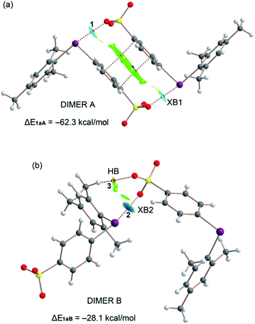
As described above, the solid-state architecture of compound 1a is different from that of 1b, 2, and 3 and the tetrameric motif observed in these three latter crystals is not present in 1a, while the two dimeric motifs A and B are present with minor differences in the interaction pattern with respect to 1b, 2, and 3 (Fig. 7). QTAIM/NCIplot analysis reveals that dimer A in 1a is assembled via two XBs (denoted as XB1) and one π-stacking, while dimer B is assembled via one single XB (denoted as XB2) and a weak ancillary C–H⋯O HB between one methyl group and one O atom of the sulfonate group. Consistent with these interaction patterns, the stabilization energy of dimer A (−62.3 kcal mol−1) is much greater than that of dimer B (−28.1 kcal mol−1).
Finally, taking into consideration that the σ-hole opposite the benzenesulfonate group is more positive than the other one, the fact that XB1 is shorter and stronger than XB2 can probably be explained considering the favorable interplay between the π-stacking and the XBs in dimers A. That is, the co-existing π-stacking and XB interactions reinforce each other.
Conclusion
The results reported in this paper prove that the high directionality of XB makes this interaction suitable for the formation of XOFs if the involved tectons are able to translate this interaction feature into a crystal architecture feature. With the aim of preparing the first one-component 3D XOFs, we focused our attention on zwitterionic aryliodonium tectons on the assumption that the geometrical constraints resulting from the tendency of the hypervalent iodine atoms of these derivatives to act as bidentate XB donors might favor XOF formation vs. interpenetration. Thanks to the electrostatic attraction between the cationic XB donor and the anionic XB acceptor, these hypervalent iodine atoms tend to form remarkably strong XBs thus enabling the formation of XOFs robust enough to survive when the water occupying the channels is almost quantitatively removed and readsorbed.Specifically, the single crystal X-ray analyses of 1a and 1b, the two polymorphic crystals formed by one of the zwitterionic 4-(aryliodonium)benzenesulfonates described here, reveal the presence of porous architectures wherein parallel channels are arranged in honeycomb and rectangular patterns, respectively. These two polymorphs are the first cases of one-component 3D XOFs reported up to now. The diameter of the channels spans the range 1.0–1.2 nanometers and the percentage of empty volume varies from 22.5 to 25.0. The powder X-ray analysis shows that no change of the crystalline architecture occurs when the solvent is removed from the cavities or when it refills the emptied cavities. Computation of MEP surfaces of the zwitterions confirms the relevance of the iodine σ-holes in determining the charge assisted XBs driving the formation of the observed architectures, and QTAIM/NCIplot analyses prove the robustness of these interactions. Importantly, while the porosity of 1a and 1b is not particularly high, the relevance of the obtainment of these systems consists in the fact that their crystalline architectures afford a proof of concept for the potential of zwitterionic aryliodonium tectons in affording robust one-component 3D XOFs. Greater porosity might be obtained by modifying the structure of the used zwitterionic aryliodonium tectons, e.g., by employing zwitterions with an increased separation between the anionic and cationic sites.
Data availability
Crystallographic data for 1–3 has been deposited at the Cambridge Crystallographic Data Centre under CCDC 2096180, 2096183, 2096184 and 2096193 and can be obtained from https://www.ccdc.cam.ac.uk/data request/cif. The associated data are available from the authors upon reasonable request.Author contributions
N. S. S. and O. S. K. – investigation; P. S. P., D. M. I., M. S. Yu. and R. M. G. – data curation; D. M. I. and M. S. Yu. – formal analysis; P. S. P., T. W., V. V. Zh., A. F. and V. Yu. K. – project administration; N. S. S., A. F. and V. Yu. K. – writing the original draft; P. S. P., T. W., V. V. Zh. and G. R. – proofreading of the original draft; N. S. S. and G. R. – funding acquisition.Conflicts of interest
There are no conflicts to declare.Acknowledgements
This work was funded by the Russian Science Foundation grant 21-73-00148 (Synthetic part and studies of physicochemical properties of XOFs) and the Ministry of Science and Higher Education of the Russian Federation in the framework of the “Mega-grant” project (No. 075-15-2021-585; crystal engineering). The authors are grateful to the Center for X-ray Diffraction Studies, Magnetic Resonance Research Center, and Center for Chemical Analysis and Materials Research (Saint Petersburg State University) and the Tomsk Regional Core Shared Research Facilities Centre (National Research Tomsk State University) for the physicochemical studies. The TG/DSC study was carried out using the core facilities of “Physical and Chemical Methods of Analysis” (National Research Tomsk Polytechnic University). O. G. and Y. Y. are also grateful to the JST-ERATO Yamauchi Materials Space-Tectonics Project (JPMJER2003). This work was performed in part at the Queensland node of the Australian National Fabrication Facility, a company established under the National Collaborative Research Infrastructure Strategy to provide nano and microfabrication facilities for Australia’s researchers.References
- H. Li, L. Li, R.-B. Lin, W. Zhou, Z. Zhang, S. Xiang and B. Chen, EnergyChem, 2019, 1, 100006 CrossRef.
- Á. Berenguer-Murcia, J. P. Marco-Lozar and D. Cazorla-Amorós, Chem. Rec., 2018, 18, 900–912 CrossRef PubMed.
- D. Banerjee, C. M. Simon, S. K. Elsaidi, M. Haranczyk and P. K. Thallapally, Chem, 2018, 4, 466–494 CAS.
- X. Zou and G. Zhu, Adv. Mater., 2018, 30, 1700750 CrossRef PubMed.
- O. Guselnikova, Y. Kalachyova, R. Elashnikov, M. Cieslar, Z. Kolska, P. Sajdl, P. Postnikov, V. Svorcik and O. Lyutakov, Microporous Mesoporous Mater., 2020, 309, 110577 CrossRef CAS.
- Y. Wang, H. Jin, Q. Ma, K. Mo, H. Mao, A. Feldhoff, X. Cao, Y. Li, F. Pan and Z. Jiang, Angew. Chem., Int. Ed., 2020, 59, 4365–4369 CrossRef CAS PubMed.
- S. Feng, Y. Shang, Z. Wang, Z. Kang, R. Wang, J. Jiang, L. Fan, W. Fan, Z. Liu, G. Kong, Y. Feng, S. Hu, H. Guo and D. Sun, Angew. Chem., Int. Ed., 2020, 59, 3840–3845 CrossRef CAS PubMed.
- L. Zhu, D. Shen and K. H. Luo, J. Hazard. Mater., 2020, 389, 122102 CrossRef CAS PubMed.
- T. Islamoglu, Z. Chen, M. C. Wasson, C. T. Buru, K. O. Kirlikovali, U. Afrin, M. R. Mian and O. K. Farha, Chem. Rev., 2020, 120, 8130–8160 CrossRef CAS PubMed.
- N. Zhang, A. Ishag, Y. Li, H. Wang, H. Guo, P. Mei, Q. Meng and Y. Sun, J. Cleaner Prod., 2020, 277, 123360 CrossRef CAS.
- S. Sudan, A. Gładysiak, B. Valizadeh, J.-H. Lee and K. C. Stylianou, Inorg. Chem., 2020, 59, 9029–9036 CrossRef CAS PubMed.
- D. A. Anito, T.-X. Wang, Z.-W. Liu, X. Ding and B.-H. Han, J. Hazard. Mater., 2020, 400, 123188 CrossRef CAS PubMed.
- X. Fan and Y. Jiao, in Sustainable Nanoscale Engineering, Elsevier, 2020, pp. 115–137 Search PubMed.
- T. A. Goetjen, J. Liu, Y. Wu, J. Sui, X. Zhang, J. T. Hupp and O. K. Farha, Chem. Commun., 2020, 56, 10409–10418 RSC.
- F. Jin, J. Liu, Y. Chen and Z. Zhang, Angew. Chem., Int. Ed., 2021, 60, 14222–14235 CrossRef CAS PubMed.
- F. N. Al-Rowaili, A. Jamal, M. S. Ba Shammakh and A. Rana, ACS Sustainable Chem. Eng., 2018, 6, 15895–15914 CrossRef CAS.
- O. Guselnikova, A. Trelin, E. Miliutina, R. Elashnikov, P. Sajdl, P. Postnikov, Z. Kolska, V. Svorcik and O. Lyutakov, ACS Appl. Mater. Interfaces, 2020, 12, 28110–28119 CrossRef CAS PubMed.
- W. Yang, A. Greenaway, X. Lin, R. Matsuda, A. J. Blake, C. Wilson, W. Lewis, P. Hubberstey, S. Kitagawa, N. R. Champness and M. Schröder, J. Am. Chem. Soc., 2010, 132, 14457–14469 CrossRef CAS PubMed.
- J. Lü, C. Perez-Krap, M. Suyetin, N. H. Alsmail, Y. Yan, S. Yang, W. Lewis, E. Bichoutskaia, C. C. Tang, A. J. Blake, R. Cao and M. Schröder, J. Am. Chem. Soc., 2014, 136, 12828–12831 CrossRef PubMed.
- K.-D. Zhang, J. Tian, D. Hanifi, Y. Zhang, A. C.-H. Sue, T.-Y. Zhou, L. Zhang, X. Zhao, Y. Liu and Z.-T. Li, J. Am. Chem. Soc., 2013, 135, 17913–17918 CrossRef CAS PubMed.
- J. Luo, J.-W. Wang, J.-H. Zhang, S. Lai and D.-C. Zhong, CrystEngComm, 2018, 20, 5884–5898 RSC.
- B. Wang, R.-B. Lin, Z. Zhang, S. Xiang and B. Chen, J. Am. Chem. Soc., 2020, 142, 14399–14416 CrossRef CAS PubMed.
- P. Li, M. R. Ryder and J. F. Stoddart, Acc. Mater. Res., 2020, 1, 77–87 CrossRef CAS.
- T. Adachi and M. D. Ward, Acc. Chem. Res., 2016, 49, 2669–2679 CrossRef CAS PubMed.
- A. Pulido, L. Chen, T. Kaczorowski, D. Holden, M. A. Little, S. Y. Chong, B. J. Slater, D. P. McMahon, B. Bonillo, C. J. Stackhouse, A. Stephenson, C. M. Kane, R. Clowes, T. Hasell, A. I. Cooper and G. M. Day, Nature, 2017, 543, 657–664 CrossRef CAS PubMed.
- I. Hisaki, C. Xin, K. Takahashi and T. Nakamura, Angew. Chem., Int. Ed., 2019, 58, 11160–11170 CrossRef CAS PubMed.
- J. Lü and R. Cao, Angew. Chem., Int. Ed., 2016, 55, 9474–9480 CrossRef PubMed.
- M. A. Little and A. I. Cooper, Adv. Funct. Mater., 2020, 30, 1909842 CrossRef CAS.
- S. Shankar, O. Chovnik, L. J. W. Shimon, M. Lahav and M. E. van der Boom, Cryst. Growth Des., 2018, 18, 1967–1977 CrossRef CAS.
- N. Chongboriboon, K. Samakun, T. Inprasit, F. Kielar, W. Dungkaew, L. W.-Y. Wong, H. H.-Y. Sung, D. B. Ninković, S. D. Zarić and K. Chainok, CrystEngComm, 2020, 22, 24–34 RSC.
- L. González, S. Graus, R. M. Tejedor, P. López, J. Elguero, J. L. Serrano and S. Uriel, CrystEngComm, 2018, 20, 3167–3170 RSC.
- P. Metrangolo, F. Meyer, T. Pilati, G. Resnati and G. Terraneo, Angew. Chem., Int. Ed., 2008, 47, 6114–6127 CrossRef CAS PubMed.
- C. B. Aakeröy and C. L. Spartz, in Halogen Bonding I, Springer, 2014, pp. 155–182 Search PubMed.
- S. v. Lindeman, J. Hecht and J. K. Kochi, J. Am. Chem. Soc., 2003, 125, 11597–11606 CrossRef CAS PubMed.
- P. Metrangolo, F. Meyer, T. Pilati, D. M. Proserpio and G. Resnati, Chem.–Eur. J., 2007, 13, 5765–5772 CrossRef CAS PubMed.
- R. Thaimattam, C. V. K. Sharma, A. Clearfield and G. R. Desiraju, Cryst. Growth Des., 2001, 1, 103–106 CrossRef CAS.
- C. A. Gunawardana, M. Đaković and C. B. Aakeröy, Chem. Commun., 2018, 54, 607–610 RSC.
- S. M. Oburn, C. L. Santana, E. Elacqua and R. H. Groeneman, CrystEngComm, 2020, 22, 4349–4352 RSC.
- G. Gong, S. Lv, J. Han, F. Xie, Q. Li, N. Xia, W. Zeng, Y. Chen, L. Wang, J. Wang and S. Chen, Angew. Chem., 2021, 133, 14957–14961 CrossRef.
- R. B. Walsh, C. W. Padgett, P. Metrangolo, G. Resnati, T. W. Hanks and W. T. Pennington, Cryst. Growth Des., 2001, 1, 165–175 CrossRef CAS.
- G. Marras, P. Metrangolo, F. Meyer, T. Pilati, G. Resnati and A. Vij, New J. Chem., 2006, 30, 1397 RSC.
- J. Martí-Rujas, L. Colombo, J. Lü, A. Dey, G. Terraneo, P. Metrangolo, T. Pilati and G. Resnati, Chem. Commun., 2012, 48, 8207 RSC.
- K. Raatikainen and K. Rissanen, Chem. Sci., 2012, 3, 1235 RSC.
- M. S. Yusubov, A. V. Maskaev and V. V. Zhdankin, Arkivoc, 2011, 2011, 370–409 Search PubMed.
- E. Merritt and B. Olofsson, Angew. Chem., Int. Ed., 2009, 48, 9052–9070 CrossRef CAS PubMed.
- L. Catalano, G. Cavallo, P. Metrangolo, G. Resnati and G. Terraneo, in Topics in Current Chemistry, Springer Verlag, 2016, vol. 373, pp. 289–309 Search PubMed.
- F. Bailly, P. Barthen, H. J. Frohn and M. Köckerling, Z. Anorg. Allg. Chem., 2000, 626, 2419–2427 CrossRef CAS.
- N. E. Zhukhlistova, G. N. Tishchenko, T. P. Tolstaya and L. D. Asulyan, Crystallogr. Rep., 2001, 46, 631–635 CrossRef.
- P. S. Postnikov, O. A. Guselnikova, M. S. Yusubov, A. Yoshimura, V. N. Nemykin and V. V. Zhdankin, J. Org. Chem., 2015, 80, 5783–5788 CrossRef CAS PubMed.
- M. S. Yusubov, D. Yu. Svitich, A. Yoshimura, B. J. Kastern, V. N. Nemykin and V. V. Zhdankin, Eur. J. Org. Chem., 2015, 2015, 4831–4834 CrossRef CAS.
- G. Cavallo, J. S. Murray, P. Politzer, T. Pilati, M. Ursini and G. Resnati, IUCrJ, 2017, 4, 411–419 CrossRef CAS PubMed.
- N. S. Soldatova, V. V. Suslonov, T. Yu. Kissler, D. M. Ivanov, A. S. Novikov, M. S. Yusubov, P. S. Postnikov and V. Yu. Kukushkin, Crystals, 2020, 10, 230 CrossRef CAS.
- N. S. Soldatova, P. S. Postnikov, V. V. Suslonov, T. Yu. Kissler, D. M. Ivanov, M. S. Yusubov, B. Galmés, A. Frontera and V. Yu. Kukushkin, Org. Chem. Front., 2020, 7, 2230–2242 RSC.
- F. Heinen, E. Engelage, A. Dreger, R. Weiss and S. M. Huber, Angew. Chem., Int. Ed., 2018, 57, 3830–3833 CrossRef CAS PubMed.
- F. Heinen, E. Engelage, C. J. Cramer and S. M. Huber, J. Am. Chem. Soc., 2020, 142, 8633–8640 CrossRef CAS PubMed.
- F. Heinen, D. L. Reinhard, E. Engelage and S. M. Huber, Angew. Chem., Int. Ed., 2021, 60(10), 5069–5073 CrossRef CAS PubMed.
- R. L. Sutar and S. M. Huber, ACS Catal., 2019, 9, 9622–9639 CrossRef CAS.
- C. R. Hubbard, V. L. Himes, A. D. Mighell and S. W. Page, Acta Crystallogr., Sect. B: Struct. Crystallogr. Cryst. Chem., 1980, 36, 2819–2821 CrossRef.
- D. D. DesMarteau, W. T. Pennington, V. Montanari and B. H. Thomas, J. Fluorine Chem., 2003, 122, 57–61 CrossRef CAS.
- M. W. Justik, J. D. Protasiewicz and J. B. Updegraff, Tetrahedron Lett., 2009, 50, 6072–6075 CrossRef CAS.
- R. Robidas, V. Guérin, L. Provençal, M. Echeverria and C. Y. Legault, Org. Lett., 2017, 19, 6420–6423 CrossRef CAS PubMed.
- P. Caramenti, S. Nicolai and J. Waser, Chem.–Eur. J., 2017, 23, 14702–14706 CrossRef CAS PubMed.
- A. Yoshimura, M. T. Shea, O. Guselnikova, P. S. Postnikov, G. T. Rohde, A. Saito, M. S. Yusubov, V. N. Nemykin and V. V. Zhdankin, Chem. Commun., 2018, 54, 10363–10366 RSC.
- M. S. Yusubov, R. Y. Yusubova, V. N. Nemykin and V. V. Zhdankin, J. Org. Chem., 2013, 78, 3767–3773 CrossRef CAS PubMed.
- M. S. Yusubov, N. S. Soldatova, P. S. Postnikov, R. R. Valiev, D. Y. Svitich, R. Y. Yusubova, A. Yoshimura, T. Wirth and V. V. Zhdankin, Eur. J. Org. Chem., 2018, 2018, 640–647 CrossRef CAS.
- N. Soldatova, P. Postnikov, O. Kukurina, V. V Zhdankin, A. Yoshimura, T. Wirth and M. S. Yusubov, Beilstein J. Org. Chem., 2018, 14, 849–855 CrossRef CAS PubMed.
- N. S. Antonkin, Y. A. Vlasenko, A. Yoshimura, V. I. Smirnov, T. N. Borodina, V. V. Zhdankin, M. S. Yusubov, A. Shafir and P. S. Postnikov, J. Org. Chem., 2021, 86, 7163–7178 CrossRef CAS PubMed.
- L. D. Caspers, J. Spils, M. Damrath, E. Lork and B. J. Nachtsheim, J. Org. Chem., 2020, 85, 9161–9178 CrossRef CAS PubMed.
- A. Bondi, J. Phys. Chem., 1964, 68, 441–451 CrossRef CAS.
- A. L. Spek, PLATON, A Multipurpose Crystallographic Tool, 2005, Utrecht University, Utrecht, The Netherlands Search PubMed.
- J. Jagiello, J. Kenvin, A. Celzard and V. Fierro, Carbon, 2019, 144, 206–215 CrossRef CAS.
Footnote |
| † Electronic supplementary information (ESI) available. CCDC 2096180, 2096183, 2096184 and 2096193. For ESI and crystallographic data in CIF or other electronic format see https://doi.org/10.1039/d2sc00892k |
| This journal is © The Royal Society of Chemistry 2022 |

