
 Open Access Article
 This Open Access Article is licensed under a Creative Commons Attribution-Non Commercial 3.0 Unported Licence
Structure formation and coarsening kinetics of phase-separated spin-coated ethylcellulose/hydroxypropylcellulose films†
Pierre
Carmona
 *ab,
Magnus
Röding
ac,
Aila
Särkkä
c,
Christian
von Corswant
d,
Eva
Olsson
b and
Niklas
Lorén
*ab
*ab,
Magnus
Röding
ac,
Aila
Särkkä
c,
Christian
von Corswant
d,
Eva
Olsson
b and
Niklas
Lorén
*ab
aUnit Product Design, Department Agriculture and Food, Division Bioeconomy and Health, RISE Research Institute of Sweden, Gothenburg, Sweden. E-mail: pierre.carmona@ri.se; niklas.loren@ri.se
bDivision Nano-and BioPhysics, Department of Physics, Chalmers University of Technology, Gothenburg, Sweden
cDepartment of Mathematical Sciences, Chalmers University of Technology and Gothenburg University, Gothenburg, Sweden
dOral Product Development, Pharmaceutical Technology & Development, Operations, AstraZeneca, Gothenburg, Sweden
First published on 30th March 2022
Abstract
Porous phase-separated ethylcellulose/hydroxypropylcellulose (EC/HPC) films are used to control drug transport from pharmaceutical pellets. The drug transport rate is determined by the structure of the porous films that are formed as water-soluble HPC leaches out. However, a detailed understanding of the evolution of the phase-separated structure in the films is lacking. In this work, we have investigated EC/HPC films produced by spin-coating, mimicking the industrial fluidized bed spraying. The aim was to investigate film structure evolution and coarsening kinetics during solvent evaporation. The structure evolution was characterized using confocal laser scanning microscopy and image analysis. The effect of the EC:HPC ratio (15 to 85 wt% HPC) on the structure evolution was determined. Bicontinuous structures were found for 30 to 40 wt% HPC. The growth of the characteristic length scale followed a power law, L(t) ∼ t(n), with n ∼ 1 for bicontinuous structures, and n ∼ 0.45–0.75 for discontinuous structures. The characteristic length scale after kinetic trapping ranged between 3.0 and 6.0 μm for bicontinuous and between 0.6 and 1.6 μm for discontinuous structures. Two main coarsening mechanisms could be identified: interfacial tension-driven hydrodynamic growth for bicontinuous structures and diffusion-driven coalescence for discontinuous structures. The 2D in-plane interface curvature analysis showed that the mean curvature decreased as a function of time for bicontinuous structures, confirming that interfacial tension is driving the growth. The findings of this work provide a good understanding of the mechanisms responsible for morphology development and open for further tailoring of thin EC/HPC film structures for controlled drug release.
1 Introduction
Controlled drug release formulations are used to deliver drugs at predetermined rates and periods of time in the body to optimize the therapeutic effect of the drug and minimize possible side effects. One means of drug administration is to use a pellet, that contains a drug reservoir coated with a thin, phase separated film. When in contact with body liquids, the water-soluble phase of the film is leached out and a porous network structure is formed. The porous microstructure of the pellet coating determines the mass transport of the drug from the core to the surrounding liquids in the body. By controlling the manufacturing and formulation, and consequently the coating structure, the drug release rate can be tailored.1 Porous polymer phase-separated films have shown good efficiency in controlling the drug transport.2 In this work, the two cellulose derivatives ethylcellulose (EC) and hydroxypropylcellulose (HPC) are used to make thin phase-separated films. EC and HPC are well-established in the pharmaceutical industry for controlled release applications.3Industrial coating of drug-containing pellets with thin phase-separated films is often performed batch-wise using fluidized bed spraying. One challenge is to relate the properties of the obtained polymer coating to the production process of the pellets. During spraying, small droplets containing EC, HPC, and ethanol hit the pellet and form a coating. Many mechanisms are involved in the formation of the multilayer phase-separated films on the pellets, and they compete in a complex and time-dependent manner. Examples of involved mechanisms are phase separation, kinetic trapping by viscosity increase, rewetting, solvent evaporation, and solvent quench to mention some. The kinetics of phase separation are directly related to the film structure. By determining the kinetics during solvent quenching it would be possible to understand the different mechanisms of phase separation and coarsening that influence the final structure.
A fluidized bed is a challenging environment for observing the multilayer formation and phase separation during solvent evaporation in a thin film. Spin-coating is a technique where phase separation during solvent evaporation in a thin film is much easier to follow and understand than in the industrial process. Therefore, spin-coating was used in this work to mimic the structure formation occurring during fluidized bed spraying. It is a widely used technique for making uniform polymer films with high reproducibility of the obtained film structure. In a previous work,4 spin-coating was utilized to form thin EC/HPC films, and the influence of the spin-coating parameters on the final dried structure was determined. Fig. 1 shows the formation of a spin-coated porous film. First, EC and HPC are mixed with a common solvent e.g. ethanol, forming a one-phase polymer solution. Then, during spin-coating, solvent evaporation occurs, and a dry film is produced. While ethanol is evaporating, EC and HPC are phase separating. Finally, when in contact with water, the dissolution and leaching of the water-soluble HPC leads to the formation of a porous (water-insoluble) EC matrix through which the drug flows or diffuses.
 | ||
| Fig. 1 Illustration of the formation of a porous phase-separated film made of EC and HPC using spin coating with evaporation of ethanol and kinetic trapping (top). With subsequent leaching of the water-soluble HPC phase (bottom left), such a coating around a drug pellet facilitates controlled release of the drug (bottom right). | ||
There are two phase separation mechanisms occurring in polymer mixtures: spinodal decomposition (corresponding to the unstable region in the phase diagram) and nucleation and growth5 (corresponding to the metastable region in the phase diagram). The nucleation and growth phase separation mechanism describes the formation of a heterogeneous structure from a homogenous mixture, initiated by a nuclei.6 This leads to discontinuous structures where different sized droplet like inclusions appear at different times. The spinodal decomposition phase separation mechanisms involve instantaneous growth of concentration fluctuations in the mixture with formation of a self-similar structure with a characteristic wavelength.7–10 With spinodal decomposition7 in bulk, the system first evolves to a bicontinuous structure, and then the structure either develops to a bicontinuous structure, where the polymer phases are interconnected, or it develops to a discontinuous morphology via a percolation-to-cluster-transition (PCT), where droplets of one polymer are distributed in the other polymer phase, depending on the phase volume. For the discontinuous morphology, the droplets appear at the same time during the structure evolution and have similar sizes. In critical and near-critical mixtures (which correspond to a system specific concentration interval), each phase keeps percolation. However, in off-critical mixtures as phase separation proceeds the minority phase cannot keep the percolation and the system undergoes PCT.11 After this transition the system cannot minimize its surface energy anymore by surface diffusion because of an entropy barrier preventing the bulk diffusion mechanism.12 Several steps can be identified: first the percolating morphology is broken into grains of partly branched substructures producing a broad cluster distribution. Secondly, when all percolation paths have been destroyed the structure cuts its strands and a structure with inclusions are formed. Finally, after the PCT, the structure can continue to grow through coalescence or Ostwald ripening.
The growth of the bicontinuous or discontinuous structures in phase-separated (bio)polymer mixtures are governed by different coarsening mechanisms: hydrodynamic growth,8 droplet coalescence,13 and Ostwald ripening14,15 illustrated in Fig. 2. Hydrodynamic growth takes place within a bicontinuous structure due to differences in the Laplace pressure which corresponds to the pressure difference between the inside and outside of a curved surface between two phases and is caused by the surface tension at the interface. The Laplace pressure pLaplace is proportional to the product of the interfacial tension γ and the curvature16 1/R (where R is the radius); pLaplace ∼ γ/R. The pressure gradient between the thinner arms (regions with high curvature) and the thicker area (region with smaller curvature) shown in Fig. 2a (p1,…,p5 > PA) causes a Poiseuille flow of material from the outside arms to the inner thicker areas, causing hydrodynamic growth.
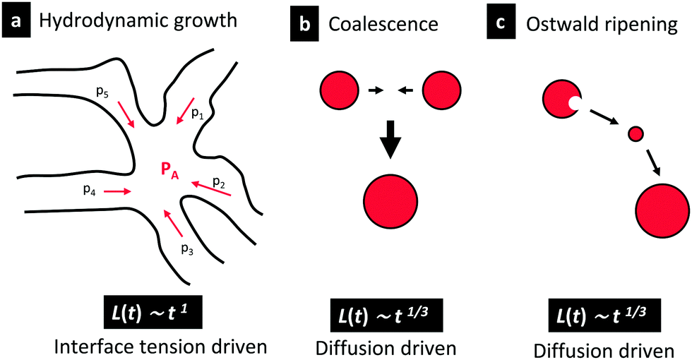 | ||
| Fig. 2 Illustration of the three coarsening mechanisms, (a) hydrodynamic growth, (b) coalescence, and (c) Ostwald ripening. in the bottom, the corresponding time dependencies are shown. | ||
During coalescence of the discontinuous structures, the droplets merge to form new larger droplets.13 After the creation of a connecting bridge between the two surfaces of the droplets, the speed of the coalescence results in a competition between the capillary forces in favor of the merge and the viscous forces slowing it down.17 The coalescence can be induced by Brownian motion, concentration gradients, or by collision-induced phenomena.18 During Ostwald ripening, smaller droplets feed larger droplets that grow and expand.14,15 Both coalescence and Ostwald ripening are governed by diffusion.
All these growth mechanisms are time-dependent, and the characteristic length scale L(t) approximately follows a time-dependent power law function, L(t) ∼ tn, where the exponent n depends on the type of coarsening mechanism(s).19 Bray et al.18,20 studied this exponent and found two regimes: the diffusive regime and the hydrodynamic regime, where the exponent n is equal to:
The growth law L(t) ∼ t(2/3) was first predicted by Furukawa26 under the conditions of capillary and inertial effects. Kendon et al.27 used lattice Boltzmann simulations and explained that the exponent 2/3 for the inertial regime has never been observed experimentally, partly because the time needed for observing this regime is very long. In addition, a n =2/3 regime has been observed at late times in simulations of two-dimensional binary liquids.10,27–29
The theories and simulations mentioned above were developed for bulk 3D systems. When studying phase separation in thin films, the confinement effect needs to be taken into account. During shrinkage of the film the phase separation might undergo a transition from 3D to nearly 2D structure development, and the cross-over occurs when the characteristic length scale of the structure is in the order of the film thickness.30
Phase separation in confinement has been studied before.31–38 It has been shown that the time dependency can be influenced by the confinement. In bulk in 3D, as explained in the previous section the length scale follows a n = 1 behavior (hydrodynamic regime). However, for 2D structure development, certain hydrodynamics instabilities do not occur and instead, coarsening occurs through a diffusive process, leading to n = 1/2.31 Note that the theories and simulations mentioned above were not developed for system undergoing a solvent quench.
In this work, phase separation is initialized by solvent evaporation (solvent quenching) which leads to a substantial increase in the viscosity of the polymer mixture. This decelerates and eventually retards the coarsening, kinetically trapping the structure in a non-equilibrium state.39
Phase separation induced by solvent evaporation is particularly challenging to understand, because during the evaporation, the state of the mixture changes continuously, and the impact of this transforming state on the structure evolution is not fully understood.40 However, in phase separation theory, the effect of solvent evaporation on the phase separation has been investigated. For example, previous theoretical work has shown that faster evaporation is expected to lead to smaller features in the final dried structures.41–43 The characteristic length scale of the phase-separated structure depends on the coarsening time but also on the time-dependent depth of the solvent quench.39,40 Faster evaporation leads to a deeper solvent quench, and the characteristic length scale is expected to become smaller.44
Cummings et al. modelled solvent evaporation during thin film formation in a phase-separating polymer mixture using linearized non-equilibrium thermodynamics.45 It was demonstrated that kinetical trapping can lead to rougher films at the air interface. Buxton et al. have simulated the evolution of a polymer blend solution undergoing solvent evaporation and phase separation as the system moved from the one-phase to the two-phase region of the ternary phase diagram.46 They predicted that phase separation occurs initially at the air-film surface, where solvent concentrations are the lowest and then progressively propagates down through the film. Zoumpouli et al. examined the effects of hydrodynamics on polymer phase separation-induced morphologies in thin films formed during evaporation.47 They used Cahn–Hilliard and Flory-Huggins theories to describe the free energy of the phase-separating systems. They found a difference between symmetric and asymmetric systems; symmetric in terms of: system solubility (same solvent solubility), substrate interactions (affinity with the substrate), or concentration (i.e. 50![[thin space (1/6-em)]](https://www.rsc.org/images/entities/char_2009.gif) :50 ratio). Asymmetric systems tend to form lamellar configurations (horizontal layers) during phase separation, whereas symmetric ones tend to form laterally segregated configurations (vertical pillars). In this work, structure evolution of asymmetric and symmetric EC/HPC systems is explored.
:50 ratio). Asymmetric systems tend to form lamellar configurations (horizontal layers) during phase separation, whereas symmetric ones tend to form laterally segregated configurations (vertical pillars). In this work, structure evolution of asymmetric and symmetric EC/HPC systems is explored.
Phase separation in EC/HPC systems has been studied previously and it was found that in most cases, the system phase-separates through spinodal decomposition.4 In addition, the 3D structure and porosity, pore size distribution, pore shape and connectivity of EC/HPC films have been determined using Focused Ion Beam Scanning Electron Microscopy (FIB-SEM) and advanced image analysis:48–51 FIB-SEM allowed identification of central features of the porous network by quantification of channels where pore paths coincide. It was found that the interconnectivity and porosity increase with increasing amount of HPC. Information about the structure could be obtained by analyzing the final dried microstructure of standing EC/HPC films or pellet coatings,49,50 but it was not possible to obtain information about the kinetics of phase separation and how that influences the final structure.
In this work, we have monitored and characterized the effect of EC:HPC ratio and film formation process on the structure evolution and the final structure in situ using confocal laser scanning microscopy. Image analysis was used to follow the 2D in-plane curvature changes and to estimate the growth rate. To the best of our knowledge, such analysis of the EC/HPC system has never been performed before.
The overall purpose of this work was to understand the mechanisms controlling the structure evolution during phase separation within a thin film formed by solvent evaporation. Here, spin-coating has been used to mimic the industrial process, allowing for observation of the structure evolution in situ. The total time of phase separation before kinetic trapping was increased by reducing the solvent evaporation rate.
The paper is structured as follows: (i) the final dried structures in thin films are presented as a function of EC:HPC ratio and two cases are identified: the bicontinuous structure and the discontinuous structure, (ii) the structure evolution is characterized in terms of time dependency and coarsening regimes, and (iii) the curvature evolution is investigated in bicontinuous structures.
2 Material and methods
2.1 Solution preparation
Solutions of HPC (Klucel Pharm HPC, grade LF, Ashland Inc, Covington, Kentucky, USA) with a mean molecular weight of 95 kDa52 and EC (Ethocel Standard Premium, viscosity 10 cps, Dow Cellulosics, Dow Chemical Company, Midland, Michigan, USA) with a mean molecular weight of 30 kDa53 were prepared. 6 wt% of polymer blends were mixed in a solution of 2 mM Na-fluorescein (CAS. 518-47-8, Sigma Aldrich, St. Louis, Missouri, USA) and ethanol (CAS. 64-17-5 AnalR NORMAPUR® 96%, VWR Chemical, Radnor, Pennsylvania, USA) and stirred overnight. The EC:HPC polymer ratios studied were 15, 20, 22, 25, 30, 35, 37, 40, 45, 50, 55, 60 and 85 wt% HPC in the polymer blend.2.2 Sample preparation by spin-coating
A spin-coater (WS-650MZ-23NPP, Laurell Technologies, North Wales, Pennsylvania, USA) was used to spin-coat the EC/HPC solutions. The volume of the solution was optimized and fixed at 200 μL. The polymer solution was deposited on the surface of a 22 mm diameter round glass bottom Petri dish (HBST-3522, Willco Wells, Amsterdam, Netherlands). The spin-coater bowl was equipped with nitrogen flow which ensures a nitrogen environment while coating. The spin speed was fixed at 2000 RPM and the spin time at 3 s. The acceleration ratio, i.e. the ratio between the acceleration speed and the spin speed, was fixed at 1:1 (e.g. for a spin speed of 2000 RPM, the acceleration was 2000 RPM s−1).
Prior to spin-coating, the solutions were kept in a 25 °C water bath and the temperature of the spin-coated bowl was 25 ± 1 °C. Films were spin-coated for only 3 s so that the film was not totally dried when the microscope observation started. The time t = 0 s corresponds to the spinning start. Directly after spinning, the Petri dish was closed with a lid and placed on the CLSM microscope stage.
2.3 Confocal scanning laser microscopy
The structure evolution of the spin-coated thin film was determined using an inverted confocal laser scanning microscope (CLSM; Leica TCS SP5, Leica, Wetzlar, Germany). A Leica 100×/1.4 PL APO oil objective was used. A 488 nm argon laser was used for excitation of Na-fluorescein. Na-fluorescein was used to stain the HPC phase. The signal emitted in the interval 500–600 nm was recorded (with a peak expected at 515 nm for maximum fluorescein emission). The theoretical lateral resolution was about 130 nm and the axial resolution was about 330 nm. Zooms 3× and 8× (FOV 52 and 19 μm respectively) were used, depending on the size of the structure observed. The images were recorded with a format of 1024 × 1024 pixels, a scanning rate of 400 Hz, and a time interval of 2.575 s between frames.The stage and objective were heated at 25 °C, with an incubation stage and controller system for microscopes (Tokai Hit, Fujinomiya-Shi, Japan).
2.4 Image analysis
The steps in the Fourier image analysis are illustrated in Fig. 3a–c. Fig. 3a shows an original CLSM micrograph of 37 wt% HPC and Fig. 3b displays the corresponding power spectrum, where each point represents a frequency contained in the real domain image. In Fig. 3c, an intensity peak that represents the dominant frequency in the Fourier space is visible showing the characteristic length scale in the original image. Finally, an estimate of the characteristic length scale L was obtained as L = FOV/μ with μ being the mean of the radial distribution representing the peak in Fig. 3c and FOV being the field of view of the micrograph in μm.
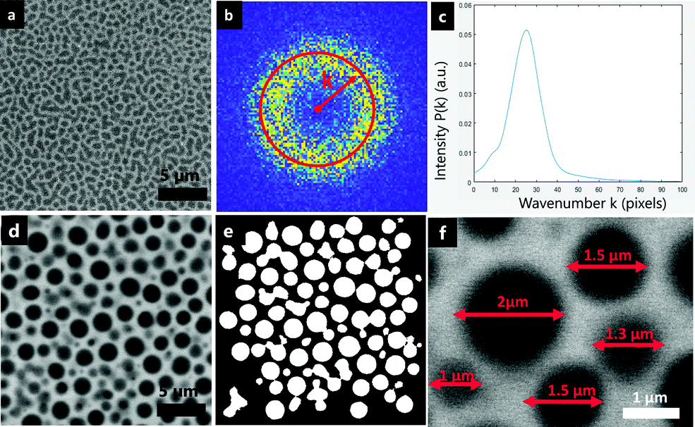 | ||
| Fig. 3 Illustration of the different steps in the image analysis methods for estimating the characteristic length scale. bicontinuous structure: (a) micrograph of a bicontinuous structure, with HPC 37 wt% at t = 256 s, (b) the corresponding power spectrum obtained by FFT, (c) the radial distribution of spectral intensity, with the peak corresponding to the characteristic length scale; discontinuous structure: (d) micrograph of a discontinuous structure, with HPC 45 wt% at 243 s, (e) the corresponding binarized image, and (f) estimation of the diameters of the inclusions. The bright phase is HPC, and the dark phase EC. | ||
For discontinuous structures, a complementary image analysis method was developed. Fig. 3d–f are showing the different steps. First, noise reduction and smoothing were performed as in Carmona et al.4 Second, the image was binarized using thresholding and the features on the edges of the image were removed, see Fig. 3e. The threshold value was selected to correspond to the volume fraction of EC and HPC on the micrograph. It was found that the HPC volume fraction corresponded to the weight fraction in the polymer blend +10%, i.e. for an EC:HPC ratio 50:50 the threshold value was 0.6. Third, the area A of each element (white objects in the figure) was calculated. Fourth, assuming that each element is a perfect circle, the (equivalent) diameter D was estimated by D = 2√(A/π). Finally, the mean diameter was calculated in micrometers by averaging the diameter values and multiplying by the pixel size. Fig. 3f shows the circular shapes of the discontinuous structure and the corresponding calculated length scales.
:45 wt%. The limits for the fitting (start and end values of t) were determined manually for each series of micrographs by locating the inflection points at the start and end of the growth (see the limits in Fig. 4 where the fitting was performed between 132 s and 243 s). The length scale of the plateau describes the characteristic length scale after the kinetic arrest of the structure.
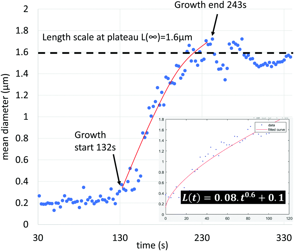 | ||
| Fig. 4 Estimation of the length scale as a function of time for the EC:HPC ratio 55:45 wt%, showing the estimated mean diameters (blue), and the power law fit (red line). The estimated start and end points of the growth stage are also indicated. In the insert, the part of the data being used for the fit is shown together with the estimated power law relationship. | ||
Fig. 5 shows an example of the estimation of the curvature at the EC/HPC 2D interface performed in the following fashion. First, a background subtraction was done by smoothing the original image with a 2D Gaussian smoothing kernel with high standard deviation (σ = 100) and subtracting the smoothed image from the original. Second, the resulting image was smoothed with another Gaussian filter (σ = 10) for noise reduction, see Fig. 5a (in dark the EC phase and in bright the HPC phase). Third, the image was binarized using thresholding, see Fig. 5b (in white the EC phase and in black the HPC phase). Fourth, the interfaces were identified and extracted as independent curves. By using the osculating radius formula, the local curvature on each point of a curve can be estimated. Fig. 5c shows the interfaces (the color scale corresponding to the curvature value, yellow indicates high curvature and blue indicates low curvature). Fig. 5d shows the distribution of the curvature values estimated from all the EC/HPC interfaces in the micrograph. Fig. 5e is an example of a curve extracted from Fig. 5c (red square). In Fig. 5f, the same curve is plotted in the xy-plane and the local curvature on each point is plotted on the z axis. For large radii of interface (straight curve), the curvature is low and for small radii of interface, the curvature is high. To follow the time dependent changes of the curvature, the mean curvature is calculated from the distribution in Fig. 5d and plotted versus time to follow the curvature evolution.
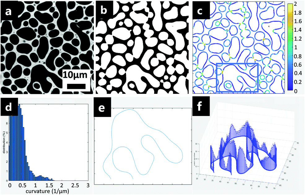 | ||
| Fig. 5 Illustration of local curvature estimation, showing (a) micrograph with HPC 37 wt% at 495 s (EC is dark, HPC is bright), (b) binarized image (EC is white, HPC is black), (c) identification of the interface and calculation of local curvatures along the interface, (d) histogram of the local curvatures, (e) example of a single interfacial curve extracted from the micrograph (red square in (c)), and (f) the corresponding local curvature values for each point along the curve in (e). | ||
3 Results and discussion
The structure evolution and the final dried structure are investigated, and different structure categories defined. An overview of the influence of the EC:HPC ratio on the in-plane structure evolution and possible explanations for the different coarsening mechanisms and phenomena involved in the structure formation are given.3.1 Film structure and phase separation mechanisms
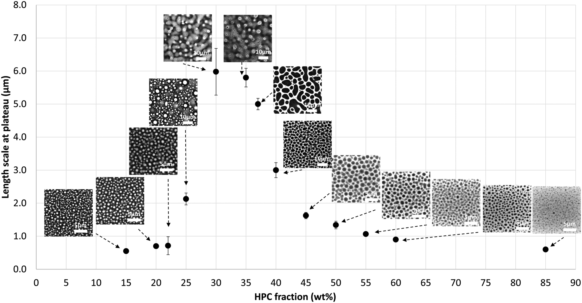 | ||
| Fig. 6 Length scale at plateau versus HPC fraction (m ± sd) together with the corresponding micrographs (HPC is bright, EC is dark). | ||
For the bicontinuous structures (30, 35, 37, 40 wt% HPC), the length scale is significantly larger, ranging between 3.0 μm to 6.0 μm. The maximum characteristic length scale is obtained at 30 wt% HPC.
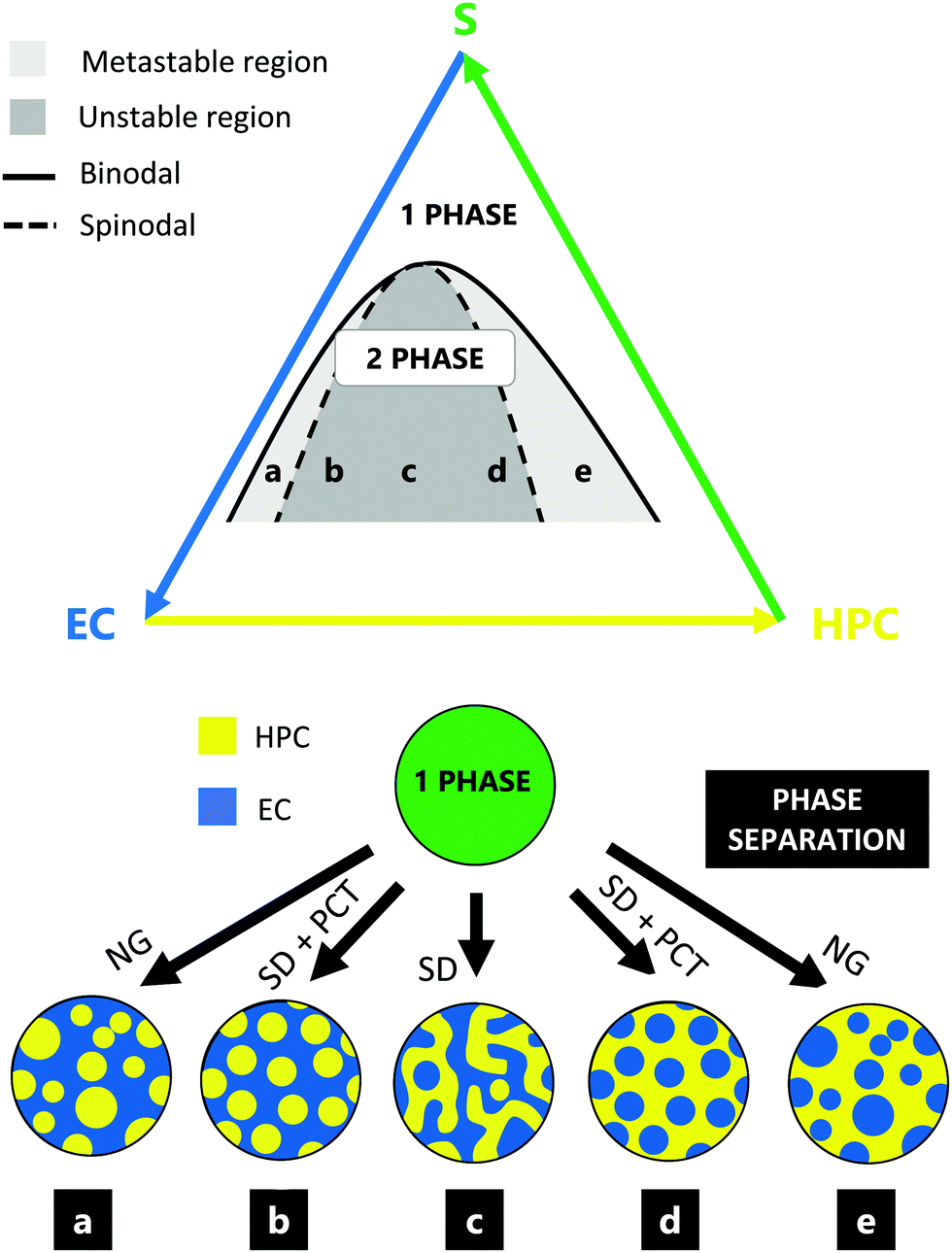 | ||
| Fig. 7 Schematic illustration of the possible structures that can be obtained after phase separation of EC and HPC, showing the ternary phase diagram of EC and HPC in ethanol (top) and some examples (a)–(e) of possible structures; (a) and (e) are in the metastable region, whereas (b)–(d) are in the unstable region. further, (c) is bicontinuous whereas the rest are discontinuous. NG is nucleation and growth; SD is spinodal decomposition; PCT is percolation to cluster transition. | ||
By analyzing the time series of the structure development of the different replicates for the ratios studied, we propose the following phase separation mechanisms. Among the cases shown in Fig. 7, we believe that the HPC fractions from 15 wt% to 20 wt% correspond to case a. The structure development of 22 wt% HPC indicates that it corresponds to case b, which is in accordance with the percolation threshold found by Marucci et al.60 at 22 wt% HPC. Below the percolation threshold HPC inclusions are trapped in an EC matrix from an early stage of the phase separation and cannot be leached out. Hence, the most probable mechanism is nucleation and growth for 15 wt% and 20 wt% HPC, and spinodal decomposition followed by PCT for 22 wt% HPC. 25 wt% HPC is believed to be on the limit of cases b and c, which is consistent with the results shown in Fig. 6. The bicontinuous structure observed for HPC fraction from 30 wt% to 40 wt% are formed by spinodal decomposition and correspond to case c. For the fractions from 45 wt% to 60 wt% HPC, discontinuous structures are observed with inclusions of similar sizes which is likely formed by spinodal decomposition followed by PCT (case d). Note that the formation of bicontinuous and discontinuous structures in the EC/HPC system is dependent on the drying kinetics. Finally, due to larger variations in droplet size it is likely that HPC 85 wt% corresponds to case e.
3.2 Coarsening of phase-separated structures
Among the 13 ratios, we identified three situations that are represented in Fig. 8: (i) bright HPC droplet-like inclusions in a dark EC matrix forming a discontinuous structure, observed for the ratios 15 to 22 wt% HPC (cases a, b in Fig. 7); (ii) a bicontinuous structure, where the volume fraction of EC and HPC are rather similar and the domains are interconnected, observed for the ratios 30 to 40 wt% HPC (case c in Fig. 7); (iii) dark EC droplet-like inclusions in a bright HPC matrix forming a discontinuous structure, observed for the ratios 45 to 85 wt% HPC (cases d, e in Fig. 7). Fig. 8 shows CLSM micrographs displaying the film structure evolution for 22, 37 and 60 wt% HPC at different key time points during the phase separation. These three HPC concentrations exemplify a discontinuous structure with HPC inclusions in a continuous EC phase (22 wt% HPC), a bicontinuous structure (37 wt% HPC), and a discontinuous structure with EC inclusions in a continuous HPC phase (60 wt% HPC). The first column corresponds to the one-phase stage before the phase separation has started. In this stage, EC and HPC are compatible, and the CLSM micrographs show a homogeneous mixture. The second column represents the phase separation start and some vague structures can be observed, including bright inclusions of HPC in the EC matrix for 22 wt% HPC, dark EC inclusions in the HPC matrix for 60 wt% HPC, and interconnected structures for 37 wt% HPC. The third column corresponds to the growth start (see also Fig. 4). The fourth column shows the structure during coarsening. The fifth column corresponds to the time when the growth ends (see also Fig. 4). After this point, the structure is kinetically trapped and does not grow anymore. Finally, the sixth column corresponds to the structure at plateau, when the evaporation process is complete, and only dried polymers remain.
 | ||
| Fig. 8 Overview of structure evolution for three different EC:HPC ratios, showing (a) EC:HPC 78:22 wt%, (b) EC:HPC 63:37 wt%, and (c) EC:HPC 40:60 wt% (HPC is bright, EC is dark). The x-axis corresponds to the key positions of the phase separation: (i) one phase, (ii) phase separation start, (iii) growth regime start (first measurement used in power law fit), (iv) coarsening regime, (v) growth regime end (last measurement used in power law fit), and (vi) plateau (kinetic trapping). where applicable, the characteristic length scale L(t) is displayed on the corresponding micrograph. The times are indicated on the pictures, with t = 0 s corresponds to the spinning start. | ||
It can be noticed from the third column to the fifth that the structure evolution is noticeably different depending on the EC:HPC ratio. As observed in Fig. 6, the length scale of the structures at the plateau in Fig. 8 is significantly larger for the bicontinuous structure (HPC 37 wt% Fig. 8b) compared to the discontinuous structures (Fig. 8a and c). In Fig. 8b secondary phase separation, where small domains appear in already phase separated bigger domains,35,62,63 is observed between 284 s and 495 s.
In further a further experiment,64 the cross section of the film was monitored, and the shrinkage of the film was investigated. By identifying the upper and lower interfaces of the film it was possible to estimate the thickness of the film during solvent evaporation. This allowed the estimation of the shrinkage rate and the estimation of the ethanol content at each time of the phase separation. The thickness of the film is in the order of 10 μm at 35 s after spinning and 2 μm at the end of the shrinkage process. The time for plateauing in shrinkage was about 200 s, which corresponds to the time when the structure is kinetically trapped, and the length scale increase is plateauing.
Each EC/HPC phase separation displayed in Fig. 8 occurs through spinodal decomposition7 which correspond to the cases b, c, d shown in Fig. 7. In the case of 37 wt% HPC (Fig. 8b), the pattern at 256 s corresponds to a typical spinodal decomposition pattern and the coarsening observed at 284 s and 328 s corresponds to the self-similar growth step of spinodal decomposition,9i.e. case c in Fig. 7. The micrographs corresponding to 22 wt% and 60 wt% HPC in Fig. 8a and c, respectively, show discontinuous structures that are likely formed through spinodal decomposition followed by PCT. The relatively slow kinetics of the structure formation allow the structure to go through PCT and to form discontinuous droplet-like structure. One explanation supporting this hypothesis is that the inclusions have similar sizes and appear at the same time. In addition, the other possible mechanism responsible for such discontinuous structures would be nucleation and growth, but that is rare in polydisperse polymer systems5 (and takes place in relatively off-critical mixtures,65 like 15 wt% and 85 wt% HPC).
It can be noticed that in this work the bicontinuous structures are obtained at ratios ranging from 30 to 40 wt% HPC and not around 50 wt% HPC as it could be expected. There is a difference between the EC/HPC weight ratio in the polymer blend and the EC/HPC volume fraction in the final dried film. When determining a thresholding value for the micrograph binarization the EC:HPC volume fraction value was investigated. It was found that the 50:50 volume fraction was obtained for approximately 40 wt% HPC in the polymer blend.
The series of CLSM micrographs in Fig. 9 is showing an example of a time-dependent structure evolution in a bicontinuous structure with 37 wt% HPC. The structure evolution is typical for the hydrodynamic growth mechanism. In the middle of the first micrograph at 264 s, a large dark EC domain with arms attached to a central body is shown. The interfacial curvature is high in the arms, which corresponds to higher Laplace pressure. The red arrows in the CLSM micrograph at 269 s represent the Laplace pressure gradients from the arms to the center causing a Poiseuille flow. Thus, EC is flowing from the arms to the center as we can observe in the series of micrograph from 264 s to 315 s. At the end of the coarsening, the interfacial curvature has decreased. Similar coarsening behavior can be seen for several domains in the bicontinuous structure evolution in Fig. 8b. Similar behavior has been found also in other systems: Bouttes et al. observed hydrodynamic coarsening for silicate melt and noticed the similar changes of curvature over time caused by flow from regions with high curvature towards the regions with low curvature.21
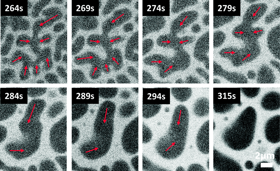 | ||
| Fig. 9 Example of hydrodynamic growth of the structure during coarsening of HPC 37 wt% spin-coated at 2000 rpm during 3 s (HPC is bright, EC is dark). the Laplace pressure gradients that cause the poiseuille flow and the hydrodynamic growth are indicated (red arrows). the scale bar displayed at 315 s is valid for all micrographs. | ||
In Fig. 8b, between 328 s and 495 s, the number of small droplets is decreasing. We believe that the small non-merged droplets were formed through secondary phase separation. The decrease of the number of droplets might be explained by Ostwald ripening (Fig. 2c), feeding bigger ones by diffusion. If Ostwald ripening is indeed taking place, it would support the idea that different coarsening mechanisms are competing during the phase separation.
In Fig. 10, three CLSM micrographs at 45 wt% HPC were selected to show an example of structure evolution that takes place during coarsening in discontinuous structures. After the PCT, the structure can grow through coalescence and/or Ostwald ripening. At t = 281 s, two dark EC inclusions start to move towards each other (indicated by red arrows) and finally coalesce at t = 302 s, which increases the inclusion size. This type of coarsening mechanism is typically observed in discontinuous structures. The initial and final states are structures with circular inclusions.
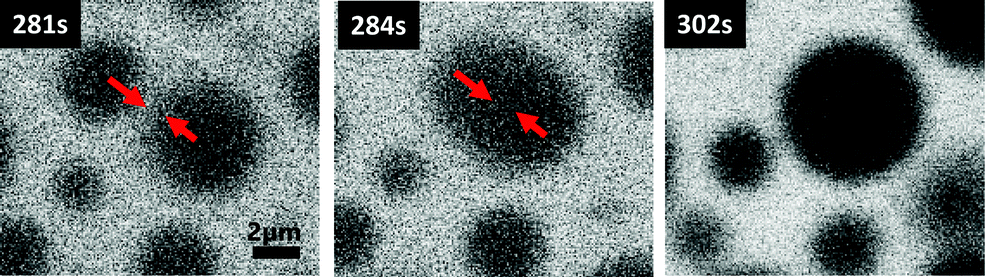 | ||
| Fig. 10 Example of coalescence observed during the phase separation of EC:HPC 45:55 wt% (HPC is bright, EC is dark). | ||
By analyzing the time-dependency of the structure evolution, we can estimate which coarsening mechanisms are dominant during the phase separation as a function of EC:HPC ratio.
3.3 The time dependent structure evolution
The length scale time dependency is defined as L(t) = a·tn + c, where a is the domain growth rate and n is the time exponent.18,20,58Fig. 11 shows the length scale time dependency and the domain growth rate of the phase-separated structure. It can be noted that the combination of a and n defines the overall coarsening rate; larger values of both a and n will correspond to a higher growth rate. The parameters a and n were estimated from the data by fitting L(t) to the experimentally obtained length scales, see Fig. 4 for procedure.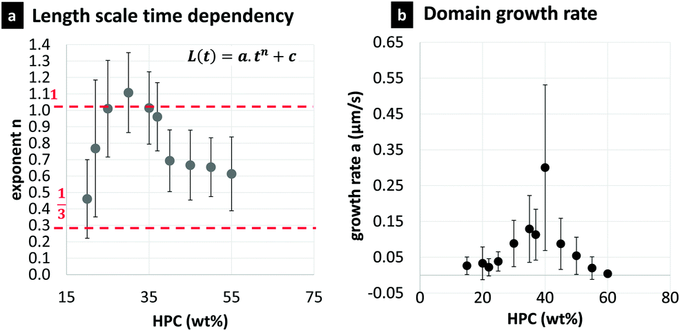 | ||
| Fig. 11 Time dependency analysis, showing (a) the parameter n versus the HPC fraction (m ± sd), also showing two different regimes of coarsening, the diffusive regime (1/3, bottom red dotted line) and the hydrodynamic regime (1, top dotted red line), (b) the parameter a corresponding to the domain growth rate versus the HPC fraction (m ± sd). | ||
In the following section we will analyze the different exponents obtained for each EC/HPC ratio and correlate the findings with corresponding coarsening mechanisms. To do so, we will compare the values determined experimentally with previous work in the literature. However, note that the theories and simulations on time dependent coarsening mentioned in the introduction do not include solvent evaporation.
In Fig. 11a, for the bicontinuous structures (30, 35, 37 wt% HPC), the time exponent is close to 1, showing that the interfacial tension-driven hydrodynamic coarsening is dominating.8 Note that 25 wt% HPC also exhibits an exponent close to 1 showing that the main growth occurs trough interfacial tension-driven hydrodynamic coarsening. Films made of 40 wt% HPC are also bicontinuous, and the time exponent is approximately 0.7. For the discontinuous structures, the exponents are lower and closer to 1/3 showing that the diffusive regime is having an important role in the coarsening. The exponent is approximately 0.45 for 20 wt% HPC. For 45, 50, and 55 wt% HPC, the exponent is close to 2/3 which is observed for asymmetric systems, i.e. where the volume fractions of the two polymers are far from 50:50. This result for EC/HPC systems is different from the results by Datt et al.29 who used 2D-simulations to calculate the growth law exponent and found the exponent 2/3 for symmetric systems, whereas asymmetric systems would have the exponent 1/3. However, the exponent value of 2/3 we observed might show that several mechanisms are competing. The exponents found for the discontinuous structures are on the same level as the exponents found in simulations performed by Akella and Gidituri.24 They showed that coalescence can follow a scaling law with an exponent of 1/2 in the outer viscous regime. The outer viscous regime is characterized by the high viscosity of the surrounding fluid, which is valid then HPC is the continuous phase, since the molecular weight of HPC is much higher than the molecular weight of EC.
In Fig. 11b the domain growth rate a is plotted versus the HPC ratio. The bicontinuous structures exhibit a higher domain growth rate (a > 0.05 μm s−1), indicating that the systems coarsen faster than the discontinuous structures. With a higher domain growth rate, it is likely that the final structure will exhibit higher length scale. These results are in accordance with the results of Fig. 6, where the length scales are larger for the bicontinuous structures than for discontinuous ones. On the contrary, the circular shapes in the discontinuous structure, mainly formed by diffusion-driven coarsening, are growing at a slower rate (a < 0.05 μm s−1) and exhibit smaller length scales. Finally, it can be noticed that 40 wt% HPC has the highest domain growth rate, supporting a bicontinuous structure in this case.
It should be mentioned that it is not unambiguous how to interpret the power law fit in this case since the system undergoes a solvent quench and the driving force for phase separation is continuously changing with solvent evaporation. However, if it is used consistently with all EC/HPC ratios, it can still be used to compare the different EC/HPC ratios. The exponent can be related to the dominant mechanisms during the short time of monitoring: between the start of the phase separation and the trapping.
3.4 2D in-plane curvature evolution
To investigate hydrodynamic coarsening, we evaluated the 2D in-plane curvature evolution. A novel image analysis method was developed to assess the time-dependent curvature changes.Fig. 12 shows an example of the curvature evolution of a bicontinuous structure (HPC 37 wt%). In Fig. 12a–c, the color maps show that the curvatures are decreasing with time. Small structures with high curvature (yellow) that are present in the beginning are disappearing and structures with low curvature (blue) are being formed. This behavior is similar to the example showed in Fig. 9. Fig. 12d–f are showing the corresponding curvature distributions. The curvature distribution at 256 s (Fig. 12d) is rather wide. However, as time passes, the curvature distributions become narrower and are shifting towards lower curvature values. This is also reflected by the decreasing mean curvature (1/Rmean) marked in Fig. 12d–f. The results in Fig. 12 show that the coarsening of the bicontinuous systems at HPC 37 wt% is governed by interfacial tension-driven hydrodynamic coarsening. This is strengthened by the results in Fig. 11 showing that the exponent in the time dependency L(t) of the formation of bicontinuous structures was close to 1, which according to Siggia8 is showing a dominance for interfacial tension-driven hydrodynamic coarsening.
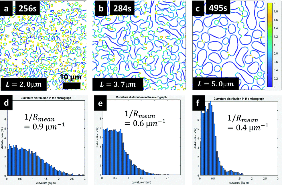 | ||
| Fig. 12 Curvature map and curvature evolution over time for EC:HPC 78:22 wt%: (a)–(c) curvature maps from 256 s to 495 s and (d)–(f) corresponding histograms of curvature, also indicating the mean curvature. t = 0 s corresponds to the spinning start. | ||
Fig. 13 shows the time-dependent evolution of the mean curvature (average of three replicates) for the bicontinuous structures (30–40 wt% HPC) and 25 wt% HPC. It can be seen that the mean curvature in the early stage of phase separation (t = 100–120 s) is high for all the ratios (in the range 0.8–0.9 μm−1), signifying that the growing shapes exhibit small radii. Typically, the curvature decreases and the shape of the structure changes rapidly between 140 and 200 s, and at about 250 s a plateau is reached due to the kinetic trapping of the structure. This behavior is observed for the ratios 30, 35, 37 and 40 wt% HPC, for which the structure is bicontinuous. For 25 wt% HPC, the drop of curvature is less pronounced. This is in accordance with the observation that the fraction 25 wt% HPC is at the limit between bicontinuous and discontinuous (limit between cases b and c in Fig. 7). It appears that for HPC 25 wt%, the phase separation happens through spinodal decomposition creating a bicontinuous structure. This structure first grows through self-similar growth and hydrodynamic coarsening (giving rise to the exponent n close to 1 in Fig. 11). Then in the end, slightly before kinetics trapping, the PCT occurs resulting in the discontinuous structure observed in Fig. 6, and in the plateauing of mean curvature reduction observed in Fig. 13.
 | ||
| Fig. 13 Mean curvature versus time for the EC:HPC ratios 25, 30, 35, 37, 40 wt% HPC. | ||
The combination of the results in Fig. 11–13 clearly shows that the growth of the bicontinuous structures (30–40 wt% HPC) in phase separated EC/HPC systems is governed by interfacial tension-driven hydrodynamical coarsening.
4 Conclusions
An experimental setup was developed and optimized to observe the structure evolution of phase separating EC/HPC systems in situ using CLSM. In addition, a new image analysis method was developed to determine the 2D in-plane curvature evolution of bicontinuous structures. The influence of the EC:HPC ratio on the final structure, structure evolution, structure growth rate, and coarsening mechanisms was determined.Two types of structures were identified: bicontinuous structures for 30, 35, 37, and 40 wt% HPC and discontinuous structures for 15, 20, 22, 45, 50, 55, 60, and 85 wt% HPC. The results indicated that 25 wt% HPC was on the limit of bicontinuous and discontinuous. The typical length scale at plateau varied between 0.6 and 1.6 μm for the discontinuous structures and between 3.0 and 6.0 μm for the bicontinuous ones. Bicontinuous structures were related to a hydrodynamic regime with interfacial tension-driven hydrodynamic coarsening. A diffusive regime with coalescence, small structures, and slow growth rate were found for the discontinuous structures. Larger structures and higher growth rates were found for the bicontinuous structures than for the discontinuous ones. The exponent n of the growth rate L(t) ∼ t(n) was also different for the two structures, n ≈ 1, for the bicontinuous structures and, n ≈ 1/3–2/3 for the discontinuous ones.
Evaluation of the curvature evolution of the interface between EC and HPC showed that the mean curvatures of bicontinuous structures decreased with time and that the curvature distributions became narrower. It was found that materials are transported from domains with high curvature to domains with low curvature, which results in growth of the low curvature parts of the structure. The observed curvature evolutions support an interfacial tension-driven hydrodynamic coarsening mechanism of the bicontinuous structures.
This work on phase separation kinetics has provided new understanding of the coarsening mechanisms controlling the phase-separated structure of thin EC/HPC films. In an ongoing study, film cross sections during the phase separation and shrinkage of the film are investigated allowing us to assess the 3D structure, estimate the evaporation rate and determine the effect of the EC:HPC ratios on the structure evolution, and characterize the transition from 3D to 2D coarsening during shrinkage.
Conflicts of interest
There are no conflicts of interest to declare.Acknowledgements
The Swedish Foundation for Strategic Research (SSF grant FID16-0013), the Swedish Research Council (VR grant 2018-03986), and the Swedish Research Council for Sustainable Development (grant 2019-01295) are gratefully acknowledged for the funding. AstraZeneca is acknowledged for the financial support and materials. Philip Townsend, RISE/Chalmers, is acknowledged for his contribution to the 2D-curvature estimation.References
- G. Tiwari, R. Tiwari, B. Sriwastawa, L. Bhati, S. Pandey, P. Pandey and S. K. Bannerjee, Int. J. Pharm. Investig., 2012, 2, 2–11 CrossRef PubMed.
- M. Marucci, G. Ragnarsson, C. von Corswant, A. Welinder, A. Jarke, F. Iselau and A. Axelsson, Int. J. Pharm., 2011, 411, 43–48 CrossRef CAS PubMed.
- P. Sakellariou and R. C. Rowe, Prog. Polym. Sci., 1995, 20, 889–942 CrossRef CAS.
- P. Carmona, M. Röding, A. Särkkä, C. Von Corswant, E. Olsson and N. Lorén, Soft Matter, 2021, 3913–3922 RSC.
- P. G. Debenedetti, in Supercritical Fluids, ed. K. A. Publishers and E. Kiran, et al., 2000, pp. 123–166 Search PubMed.
- J. W. Gibbs, The Scientific Papers of J. Willard Gibbs, Dover, New York, 1961 Search PubMed.
- J. W. Cahn, J. Chem. Phys., 1965, 42, 93–99 CrossRef CAS.
- E. D. Siggia, Phys. Rev. A: At., Mol., Opt. Phys., 1979, 20, 595–605 CrossRef CAS.
- T. Hashimoto, Phase Transitions, 1988, 12, 47–119 CrossRef CAS.
- J. E. Farrell and O. T. Valls, Phys. Rev. B: Condens. Matter Mater. Phys., 1989, 40, 7027–7039 CrossRef PubMed.
- H. Takeno, E. Nakamura and T. Hashimoto, J. Chem. Phys., 1999, 110, 3612–3620 Search PubMed.
- J. Lauger, R. Lay and W. Gronski, J. Chem. Phys., 1994, 101, 7181–7184 CrossRef.
- A. K. Chesters, Chem. Eng. Res. Des., 1991, 69, 259–270 CAS.
- P. G. De Gennes, F. Brochard-Wyart and D. Quere, Capillarity and Wetting Phenomena: Drops, Bubbles, Pearls, Waves, 2004 Search PubMed.
- M. Hill, Polymer, 1995, 36, 3369–3375 CrossRef CAS.
- A. P. Solon, J. Stenhammar, M. E. Cates, Y. Kafri and J. Tailleur, New J. Phys., 2018, 20, 075001 CrossRef.
- D. G. A. L. Aarts, H. N. W. Lekkerkerker, H. Guo, G. H. Wegdam and D. Bonn, Phys. Rev. Lett., 2005, 95, 164503 CrossRef PubMed.
- A. J. Bray, Philos. Trans. R. Soc., A, 2003, 361, 781–792 CrossRef CAS PubMed.
- J. K. G. Dhont, J. Chem. Phys., 1996, 105, 5112–5125 CrossRef CAS.
- A. J. Bray, Adv. Phys., 2010, 51, 481–587 CrossRef.
- D. Bouttes, O. Lambert, C. Claireaux, W. Woelffel, D. Dalmas, E. Gouillart, P. Lhuissier, L. Salvo, E. Boller and D. Vandembroucq, Acta Mater., 2015, 92, 233–242 CrossRef CAS.
- A. E. Bailey, W. C. Poon, R. J. Christianson, A. B. Schofield, U. Gasser, V. Prasad, S. Manley, P. N. Segre, L. Cipelletti, W. V. Meyer, M. P. Doherty, S. Sankaran, A. L. Jankovsky, W. L. Shiley, J. P. Bowen, J. C. Eggers, C. Kurta, T. Lorik, Jr., P. N. Pusey and D. A. Weitz, Phys. Rev. Lett., 2007, 99, 205701 CrossRef CAS PubMed.
- N. Lorén, A.-M. Hermansson, M. A. K. Williams, L. Lundin, T. J. Foster, C. D. Hubbard, A. H. Clark, I. T. Norton, E. T. Bergström and D. M. Goodall, Macromolecules, 2001, 34, 289–297 CrossRef.
- V. S. Akella and H. Gidituri, Chem. Phys. Lett., 2020, 758, 137917 CrossRef CAS.
- J. D. Paulsen, R. Carmigniani, A. Kannan, J. C. Burton and S. R. Nagel, Nat. Commun., 2014, 5, 4182 CrossRef PubMed.
- H. Furukawa, Phys. Rev. A: At., Mol., Opt. Phys., 1985, 31, 1103–1108 CrossRef PubMed.
- V. M. Kendon, M. E. Cates, I. Pagonabarraga, J.-C. Desplat and P. Bladon, J. Fluid Mech., 2001, 440, 147–203 CrossRef CAS.
- F. J. Alexander, S. Chen and D. W. Grunau, Phys. Rev. B: Condens. Matter Mater. Phys., 1993, 48, 634–637 CrossRef CAS PubMed.
- C. Datt, S. P. Thampi and R. Govindarajan, Phys. Rev. E: Stat., Nonlinear, Soft Matter Phys., 2015, 91, 010101 CrossRef PubMed.
- L. Sung, A. Karim, J. F. Douglas and C. C. Han, Phys. Rev. Lett., 1996, 76, 4368–4371 CrossRef CAS PubMed.
- H. Jinnai, H. Kitagishi, K. Hamano, Y. Nishikawa and M. Takahashi, Phys. Rev. E: Stat., Nonlinear, Soft Matter Phys., 2003, 67, 021801 CrossRef PubMed.
- S. Fransson, N. Loren, A. Altskar and A.-M. Hermansson, Biomacromolecules, 2009, 10, 1446–1453 CrossRef CAS.
- S. Wassén, N. Lorén, K. van Bemmel, E. Schuster, E. Rondeau and A.-M. Hermansson, Soft Matter, 2013, 9, 2738–2749 RSC.
- A. M. Zolali and B. D. Favis, Soft Matter, 2017, 13, 2844–2856 RSC.
- H. Tanaka, Phys. Rev. Lett., 1994, 72, 3690–3693 CrossRef CAS PubMed.
- K. Binder, S. Puri, S. K. Das and J. Horbach, J. Stat. Phys., 2010, 138, 51–84 CrossRef CAS.
- E. A. G. Jamie, R. P. A. Dullens and D. G. A. L. Aarts, J. Chem. Phys., 2012, 137, 204902 CrossRef CAS PubMed.
- M. B. Wise and P. C. Millett, Phys. Rev. E, 2018, 98, 022601 CrossRef CAS PubMed.
- C. Schaefer, J. J. Michels and P. Van Der Schoot, Macromolecules, 2016, 49, 6858–6870 CrossRef CAS.
- C. Schaefer, P. van der Schoot and J. J. Michels, Phys. Rev. E: Stat., Nonlinear, Soft Matter Phys., 2015, 91, 022602 CrossRef CAS PubMed.
- S. Kouijzer, J. J. Michels, M. van den Berg, V. S. Gevaerts, M. Turbiez, M. M. Wienk and R. A. J. Janssen, J. Am. Chem. Soc., 2013, 135, 12057–12067 CrossRef CAS PubMed.
- J. J. van Franeker, D. Westhoff, M. Turbiez, M. M. Wienk, V. Schmidt and R. A. J. Janssen, Adv. Funct. Mater., 2015, 25, 855–863 CrossRef CAS.
- S. Walheim, M. Böltau, J. Mlynek, K. Georg and U. Steiner, Macromolecules, 1997, 30, 4995–5003 CrossRef CAS.
- C. Schaefer, P. Van Der Schoot and J. J. Michels, Phys. Rev. E: Stat., Nonlinear, Soft Matter Phys., 2015, 91, 022602 CrossRef CAS PubMed.
- J. Cummings, J. S. Lowengrub, B. G. Sumpter, S. M. Wise and R. Kumar, Soft Matter, 2018, 14, 1833–1846 RSC.
- G. A. Buxton and N. Clarke, Europhys. Lett., 2007, 78, 56006 CrossRef.
- G. A. Zoumpouli and S. G. Yiantsios, Phys. Fluids, 2016, 28, 082108 CrossRef.
- M. Röding, C. Fager, A. Olsson, C. von Corswant, E. Olsson and N. Lorén, J. Microscopy, 2021, 281, 76–86 CrossRef PubMed.
- C. Fager, S. Barman, M. Röding, A. Olsson, N. Lorén, C. von Corswant, D. Bolin, H. Rootzen and E. Olsson, Int. J. Pharm., 2020, 587, 119622 CrossRef CAS PubMed.
- C. Fager, M. Röding, A. Olsson, N. Lorén, C. von Corswant, A. Sarkka and E. Olsson, Microsc. Microanal., 2020, 26, 837–845 CrossRef CAS PubMed.
- C. Fager, T. Gebäck, J. Hjärtstam, M. Röding, A. Olsson, N. Lorén, C. Von Corswant, A. Särkkä and E. Olsson, Chem. Eng. Sci.: X, 2021, 12, 100109 CAS.
- Ashland, (Klucel hydroxypropylcellulose, Physical and chemical properties).
- DowCellulosics, (ETHOCEL, Ethylcellulose Polymers Technical Handbook).
- N. Lorén, M. Langton and A. M. Hermansson, J. Chem. Phys., 2002, 116, 10536–10546 CrossRef.
- S. Wassén, R. Bordes, T. Gebäck, D. Bernin, E. Schuster, N. Lorén and A.-M. Hermansson, Probe diffusion in phase-separated bicontinuous biopolymer gels, 2014 Search PubMed.
- T. Fujita and M. Chen, Jpn. J. Appl. Phys., 2018, 57, 1161–1163 CrossRef.
- J. Zhu, R. Balieu, X. Lu and N. Kringos, Mater. Des., 2018, 137, 164–175 CrossRef CAS.
- H. Tanaka, J. Phys.: Condens. Matter, 2001, 13, 4637–4674 CrossRef CAS.
- D. Coeurjolly and S. Svensson, presented in part at the SCIA'03: Proceedings of the 13th Scandinavian conference on Image analysis, 2003 Search PubMed.
- M. Marucci, J. Hjärtstam, G. Ragnarsson, F. Iselau and A. Axelsson, J. Controlled Release, 2009, 136, 206–212 CrossRef CAS PubMed.
- J. J. Michels, ChemPhysChem, 2011, 12, 342–348 CrossRef CAS PubMed.
- M. Yamamura, T. Nishio, K. Toshihisa and K. Atachi, Chem. Eng. Sci., 2002, 57, 2901–2905 CrossRef CAS.
- H. Tanaka and T. Araki, Phys. Rev. Lett., 1998, 81, 389–392 CrossRef CAS.
- P. Carmona, M. Röding, A. Särkkä, C. von Corswant, E. Olsson and N. Lorén, unpublished work.
- J. Colombani and J. Bert, J. Non-Equilib. Thermodyn., 2004, 29, 1–11 Search PubMed.
Footnote |
| † Electronic supplementary information (ESI) available. See DOI: 10.1039/d2sm00113f |
| This journal is © The Royal Society of Chemistry 2022 |