 Open Access Article
Type-II BiVO4/Ni3(hexahydroxytriphenylene)2 heterojunction photoanodes for effective photoelectrochemical reaction†
Ji Won
Yoon
,
Young-Moo
Jo
and
Jong-Heun
Lee
 *
*
Department of Materials Science and Engineering, Korea University, Seoul 02841, Republic of Korea. E-mail: jongheun@korea.ac.kr
First published on 10th March 2022
Abstract
Semiconducting M3(hexahydroxytriphenylene)2 (M = Ni, Co, Cu; hexahydroxytriphenylene (HHTP)) was uniformly coated onto BiVO4 thin films via a facile solvothermal process, and the photoelectrochemical performance of the BiVO4/M3(HHTP)2 photoanodes was investigated. All three BiVO4/M3(HHTP)2 photoanodes exhibited higher photocurrent densities than pristine BiVO4. This can be attributed to the formation of type-II heterojunctions, as confirmed by ultraviolet photoelectron spectroscopy (UPS) and ultraviolet-visible spectroscopy. BiVO4/Ni3(HHTP)2 exhibited the highest photocurrent density of 4.66 mA cm−2 at 1.23 V vs. a reversible hydrogen electrode (RHE), an approximately 3.2-fold increase from that of pristine BiVO4. The results suggest that the type of metal ion in M3(HHTP)2 affects the electrical conductivity, which significantly influences the charge transport kinetics in the photoelectrochemical reactions of BiVO4. The mechanism underlying the enhanced photoelectrochemical reaction was also investigated.
Introduction
Hydrogen fuel is a sustainable energy source that can be used as an alternative to fossil fuels. Photoelectrochemical water splitting is an environment-friendly method to produce hydrogen from water by utilizing solar energy. This method has drawn significant attention owing to its potential for negligible greenhouse gas emissions. Among the diverse metal oxide photoanodes used for photoelectrochemical water splitting,1,2 BiVO4 is a promising candidate because of its 2.4–2.5 eV bandgap, which is advantageous for absorbing visible light. However, its sluggish charge transfer kinetics and short hole diffusion length hamper charge transport and separation.3 Accordingly, various methods have been considered to improve the photoelectrochemical performance of BiVO4, including surface area expansion, doping, and heterostructure design.4–8The rational design of a type-II heterojunction with another semiconductor is a promising strategy to enhance the photoelectrochemical performance of BiVO4.9–12 A type-II heterojunction established between two different semiconductors facilitates the separation of photogenerated charge carriers, preventing charge recombination losses. Because a staggered band alignment is required, it is important to consider both the energy bandgap and band positions of the two semiconductors. The light absorption rate is determined by the energy bandgap, oxygen evolution reaction (OER), or hydrogen evolution reaction (HER) based on the band positions. Various heterostructures with staggered band alignments have been proposed to compensate for the sluggish OER, such as WO3/BiVO4,5 TiO2/BiVO4,6 and BiVO4/MoS2;7 however, further enhancement of the photoelectrochemical performance is required.
In recent years, heterojunctions between metal–organic frameworks (MOFs) and BiVO4, such as BiVO4/CoNi–MOF,13 BiVO4/MIL-53(Fe),14 and BiVO4/MIL-101(Fe),15 have been investigated to improve the photoelectrochemical performance. The design and application of MOFs for photoelectrochemical reactions have been widely investigated because MOFs provide advantages such as extremely high surface area, tunable porosity, and compositional diversity and exhibit semiconducting properties. Semiconducting MOFs with suitable band structures and high electrical conductivity are promising platforms for designing photoanodes with staggered band alignments.16 Among various MOFs, M3(HHTP)2 (M = Ni, Co, and Cu; 2,3,6,7,10,11-hexahydroxytriphenylene (HHTP)) has shown good electrical conduction through π–π stacked pathways as well as suitable bandgaps for water splitting.17 Because of their conductive nature, M3(HHTP)2 photoanodes are expected to exhibit high photoelectrochemical performance. However, to the best of our knowledge, the heterojunction between BiVO4 and M3(HHTP)2 for photoelectrochemical reactions has yet to be investigated.
Herein, we report the highly efficient photoelectrochemical reaction of a BiVO4/M3(HHTP)2 photoanode. The BiVO4 film was coated onto fluorine doped tin oxide (FTO)/glass substrates by electrodeposition, then the M3(HHTP)2 was coated onto the BiVO4 film via a solvothermal reaction. All BiVO4/M3(HHTP)2 photoanodes showed significantly higher photocurrent densities than pristine BiVO4, which is attributed to the type-II heterojunctions established between BiVO4 and M3(HHTP)2. Notably, BiVO4/Ni3(HHTP)2 exhibited the highest photocurrent density of 4.66 mA cm−2, which is a 3.2-fold increase in efficiency from that of pristine BiVO4. This study reveals that the electrical conductivity of M3(HHTP)2 is dependent on the type of metal ions, which play a key role in the charge transport for photoelectrochemical reactions. The main purpose of this study is to determine the key parameters affecting the OER in BiVO4/M3(HHTP)2 heterostructure photoanodes and to understand the mechanism underlying the enhanced photoelectrochemical reaction.
Experimental
Sample preparation
BiVO4 nanoparticles were coated onto FTO/glass substrates by a modified electrodeposition method.18,19 The typical synthesis process includes an FTO/glass substrate, platinum (Pt) mesh, and Ag/AgCl/saturated NaCl as the working, counter, and reference electrodes, respectively. The precursor solution for BiVO4 electrodeposition was prepared as follows. 1.141 g of vanadium oxide sulfate hydrate (VOSO4·xH2O, 99.9%, Alfa Aesar), and 0.97014 g of bismuth nitrate pentahydrate (Bi(NO3)3·5H2O, 98.0%, Junsei) were dissolved in an aqueous HNO3 solution (100 mL, 1![[thin space (1/6-em)]](https://www.rsc.org/images/entities/char_2009.gif) :
:![[thin space (1/6-em)]](https://www.rsc.org/images/entities/char_2009.gif) 9 (v/v) mixture of 60% HNO3 and deionized (DI) water) under magnetic stirring to form a clear solution. A stabilizer solution was prepared by dissolving 32.812 g of sodium acetate in 100 mL of DI water, and then added to the Bi/V ion solution. The pH of the solution for electrodeposition was adjusted to 4.7. This mildly acidic pH solution is required for electrodeposition because no film can be deposited at pH values, in which Bi ions are soluble (pH < 2). Excessive precipitates hinder the film deposition at pH > 5.19 Electrodeposition was performed at 0.8 V for 1 h at room temperature. The prepared substrates were rinsed with DI water and annealed at 550 °C for 3 h.
9 (v/v) mixture of 60% HNO3 and deionized (DI) water) under magnetic stirring to form a clear solution. A stabilizer solution was prepared by dissolving 32.812 g of sodium acetate in 100 mL of DI water, and then added to the Bi/V ion solution. The pH of the solution for electrodeposition was adjusted to 4.7. This mildly acidic pH solution is required for electrodeposition because no film can be deposited at pH values, in which Bi ions are soluble (pH < 2). Excessive precipitates hinder the film deposition at pH > 5.19 Electrodeposition was performed at 0.8 V for 1 h at room temperature. The prepared substrates were rinsed with DI water and annealed at 550 °C for 3 h.
Ni3(HHTP)2 was coated onto the BiVO4 film via a solvothermal reaction. 2.5 mmol of nickel acetate tetrahydrate (Ni(OCOCH3)2·4H2O, 98.0%, Merck) was dissolved in 20 mL of DI water, and 1.25 mmol of 2,3,6,7,10,11-hexahydroxytriphenylene (HHTP, 95.0%, Acros Organics) was dissolved in 10 mL methanol. The two solutions were mixed and homogenized by stirring. Then, the mixed solution was placed in a Teflon-lined stainless-steel autoclave with a BiVO4/FTO/glass substrate immersed in it. The sealed autoclave was heated to 85 °C for 3.5 h. The substrates were rinsed with DI water thrice.
Results & discussion
A schematic of the procedure for preparing the BiVO4/Ni3(HHTP)2 heterojunction on an FTO/glass substrate is shown in Fig. 1. The BiVO4 thin film was anodically electrodeposited onto the FTO/glass substrate using an aqueous solution containing Bi(III) ions and V(IV) ions. This was followed by heat treatment at 500 °C for 2 h to achieve crystalline BiVO4. The BiVO4 thin film appeared as bright yellow (Fig. S1a, ESI†). The X-ray diffraction (XRD) pattern showed that the crystalline peaks are monoclinic BiVO4 (Fig. S1b, ESI†). The scanning electron microscopy (SEM) images of the BiVO4 thin film (Fig. S2a and b, ESI†) revealed that the film consists of large grains ranging from 100 to 500 nm with a thickness of 250–300 nm. The transmission electron microscopy (TEM) image and selected area electron diffraction (SAED) patterns of BiVO4 confirmed its crystalline structure. The inter-planar spacing in the lattice fringes was analyzed to be d(040) = 2.90 ± 0.1 Å (Fig. S2c, ESI†), which corresponds to the monoclinic BiVO4. Elemental mapping further confirmed that the Bi and V components were uniformly distributed along the whole grains (Fig. S2(d1)–S4, ESI†).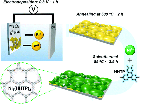 | ||
| Fig. 1 Schematic diagram of the synthesis process for the BiVO4/Ni3(HHTP)2 heterostructure on FTO/glass substrate. | ||
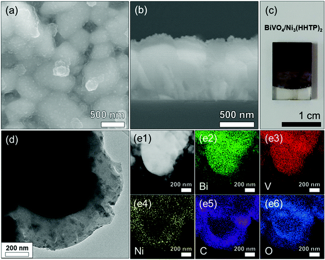
Ni3(HHTP)2 was coated onto the surface of BiVO4 by a solvothermal reaction at 85 °C for 3.5 h (Fig. 2a and b). The solvothermal reaction enables the conformal, well-attached, and uniform growth of Ni3(HHTP)2 on the BiVO4 surface. This is desirable in photoelectrochemical reactions because the strong adhesion between the BiVO4 and MOF ensures high stability. The color of the photoanode changed from bright yellow to dark green after the solvothermal growth of Ni3(HHTP)2 on the BiVO4 thin film (Fig. 2c). Close examination of the high-resolution TEM (Fig. 2d) and elemental mapping (Fig. 2e1–6) confirmed that the Ni3(HHTP)2 layer (150–200 nm thickness) was uniformly coated onto the BiVO4 surface. Owing to the XRD detection limit and the negligible number of MOFs, Ni3(HHTP)2 peaks were not observed in the XRD patterns (Fig. S3a, ESI†). To prepare a sufficient amount of Ni3(HHTP)2, the solvothermal reaction time was increased to 6 h. The detected peaks of MOF at 2θ = 5–20° were in agreement with those observed in the simulated XRD patterns of Ni3(HHTP)2 (Fig. S3b, ESI†), confirming the formation of Ni3(HHTP)2via the solvothermal reaction.20–22 Furthermore, the atomic composition of the BiVO4/M3(HHTP)2 (M = Ni, Co, Cu) was analyzed by XPS (Fig. S4–S6, ESI†), and the existence of all the elements was confirmed by peak analysis. To examine the influence of the solvothermal reaction time on the growth of Ni3(HHTP)2 on the BiVO4 surface, the reaction time was controlled up to 1 h and 6 h. As the MOF precursor solution containing nickel ions and HHTP ligands induced rapid nucleation and growth at the initial stage, the morphology of Ni3(HHTP)2 after the 1 h and 3.5 h solvothermal reactions appeared to be similar (Fig. S7a, b, ESI† and Fig. 2a, b). However, when the solvothermal reaction time increased to 6 h, a thick Ni3(HHTP)2 layer (4–5 μm) unevenly covered the BiVO4 film (Fig. S7c and d, ESI†). An excessively thick Ni3(HHTP)2 layer will affect the charge transfer within the Ni3(HHTP)2, which would deteriorate photoelectrochemical reaction. Hence, the thickness of Ni3(HHTP)2 should be optimized by controlling the solvothermal reaction time.
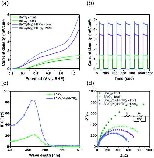
The photocurrent densities of BiVO4 and BiVO4/Ni3(HHTP)2 were evaluated in both 0.1 M Na2SO3 and 0.1 M Na2SO4 solution under front and back illumination (Fig. 3a). In BiVO4 photoanodes with sluggish charge transport kinetics, backside illumination led to a higher photocurrent density than frontside illumination because it allows the more efficient collection of photogenerated electrons.23,24 In the present study, hole-scavenging Na2SO3 was used to suppress the surface recombination of BiVO4.25 At the potential of 1.23 V vs. RHE, BiVO4 under front and back illumination showed photocurrent densities of 1.09 mA cm−2 and 1.42 mA cm−2, respectively. When Ni3(HHTP)2 was solvothermally coated onto BiVO4 for 3.5 h, the photocurrent density significantly increased to 3.45 and 4.66 mA cm−2 under front and back illumination, respectively, which is approximately 3.2 times higher than that of a pristine BiVO4 photoanode. When the solvothermal reaction time reached 6 h, however, the photocurrent density of BiVO4/Ni3(HHTP)2 significantly decreased, probably because of ineffective charge transport through the extremely thick MOF layer (Fig. S8, ESI†). The photocurrent density of BiVO4/Ni3(HHTP)2 reached 3.10 mA cm−2 at 1.23 V vs. RHE in 0.1 M Na2SO4 electrolyte (without hole-scavenging Na2SO3), suggesting that Ni3(HHTP)2 is also a promising catalyst for photoelectrochemical water splitting (Fig. S9, ESI†). It is worth noting that the photocurrent density of the BiVO4/Ni3(HHTP)2 photoanode is similar to or greater than that of previous BiVO4-based heterojunction photoanodes in the literature (Table S1, ESI†). Besides, BiVO4/Ni3(HHTP)2 showed an abrupt slope change above 1.1 V vs. RHE with or without the presence of Na2SO3. The J–V curves shown in Fig. S10 (ESI†) revealed that the current density of BiVO4 did not significantly increase in the dark, while Ni3(HHTP)2 and BiVO4/Ni3(HHTP)2 have a different increasing trend above 1.1 V vs. RHE. Therefore, the unusual increasing trend could be attributed to an intrinsic catalytic activity of Ni3(HHTP)2. The light on/off cycles of BiVO4 and BiVO4/Ni3(HHTP)2 were obtained by applying the constant potential of 1.23 V vs. RHE (Fig. 3b). Both photoanodes exhibited rapid photoresponses under initial illumination, followed by a stable steady-state, and were highly reproducible for a few cycles. The incident photon-to-electron conversion efficiency (IPCE) spectra were examined from 300 to 800 nm at 1.23 V vs. RHE to investigate the light absorption and energy conversion efficiency of BiVO4 and BiVO4/Ni3(HHTP)2 (Fig. 3c). BiVO4/Ni3(HHTP)2 reached the highest IPCE of 83.4% at λ = 460 nm, which is almost four times higher than that of pristine BiVO4. The IPCE value significantly increased throughout the entire range, indicating that Ni3(HHTP)2 promoted the effective utilization of visible light. Electrochemical impedance spectroscopy (EIS) of BiVO4 and BiVO4/Ni3(HHTP)2 was conducted at 1.23 V vs. RHE to examine the surface resistance and charge transport during photoelectrochemical reactions (Fig. 3d). The obtained Nyquist plots were fitted and simulated to determine the Rct values (charge transfer resistance at the interface between the photoanode and electrolyte) listed in Table 1. An equivalent circuit for the EIS results is shown in the inset of Fig. 3d. According to the fitted charge transfer resistance, back-illuminated BiVO4 and BiVO4/Ni3(HHTP)2 exhibited lower resistance than front-illuminated photoanodes. The results indicate that backside illumination is advantageous for collecting photogenerated electrons and can overcome the sluggish charge transport kinetics of BiVO4. Moreover, additional EIS measurements (Fig. S11a, ESI†) were conducted in the dark at 0 V to confirm a junction formed between BiVO4 and Ni3(HHTP)2. Without any external bias and light energy, the EIS spectra of BiVO4 revealed one semicircle, while BiVO4/Ni3(HHTP)2 revealed two semicircles. When Ni3(HHTP)2 formed a junction with BiVO4, the Rct values decreased from 909.5 Ω cm2 to 447.9 Ω cm2, indicating a facilitated charge transfer through the BiVO4/Ni3(HHTP)2 and electrolyte interface. In addition, the charge carrier concentration (ND) was calculated using Mott–Schottky analysis (Fig. S11b, ESI†). According to the Mott–Schottky plot, ND can be calculated using the following equation:26
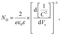 | (1) |
| Photoanode | R s (Ω cm2) | R ct (Ω cm2) |
|---|---|---|
| BiVO4 (front) | 17.3 | 1740 |
| BiVO4 (back) | 17.7 | 909.5 |
| BiVO4/Ni3(HHTP)2 (front) | 8.5 | 665.3 |
| BiVO4/Ni3(HHTP)2 (back) | 7.4 | 447.9 |
Co3(HHTP)2 and Cu3(HHTP)2 are two other potential conductive MOFs28 that were coated onto BiVO4 by a solvothermal reaction to investigate their photoelectrochemical performance. Upon their use, the photocurrent density increased to 2.25 and 1.77 mA cm−2 (Fig. S12a, ESI†). The IPCE values of BiVO4/Co3(HHTP)2 and BiVO4/Cu3(HHTP)2 were more than twice that of with pristine (Fig. S12b, ESI†). The fitted Rct values decreased as Co3(HHTP)2 and Cu3(HHTP)2 were coated onto BiVO4 (Fig. S12c, d and Table S2, ESI†). The results confirm that the formation of a heterostructure photoanode between semiconducting HHTP-based MOFs and BiVO4 could enhance photoelectrochemical reactions.29–33 Although Co3(HHTP)2 and Cu3(HHTP)2 improved the photoelectrochemical activity of BiVO4, its efficiency was lower than that of BiVO4/Ni3(HHTP)2. The higher electrochemical performance of Ni3(HHTP)2 can be understood in terms of its high electrical conductivity among the three HHTP-based MOFs. To examine this, porous M3(HHTP)2 pellets were prepared (Fig. S13a, ESI†), and their electrical conductivities were measured using the two-electrode method. The conductivities are σ = 4.45 × 10⁻⁶ S cm−1, 1.59 × 10⁻⁷ S cm−1, and 4.29 × 10⁻⁸ S cm−1 for Ni3(HHTP)2, Co3(HHTP)2, and Cu3(HHTP)2, respectively (Fig. S13b, ESI†). The conductivity of Ni3(HHTP)2 is significantly higher than those of Co3(HHTP)2 and Cu3(HHTP)2, even considering the small variation in densities, which is in line with the reported results.17 For M3(HHTP)2, the electrical conductivity is dependent on the type of metal ion with different electronic states.34 Moreover, as M3(HHTP)2 frameworks are built in stacked two-dimensional (2D) structures, the interlayer spacing (S) along the c direction also influences the conduction. In general, a higher S value with a lower strength of interaction between the 2D layers yields a higher conductivity.35 In the literature, Ni3(HHTP)2 was reported to have the highest S value (3.8 Å),36 while Cu3(HHTP)2 had the lowest (3.16 Å) among the three MOFs.17 The conductivity values in the present study and literature suggest that the high conductivity of Ni3(HHTP)2 plays a key role in the superior photoelectrochemical performance of the BiVO4/Ni3(HHTP)2 photoanode.
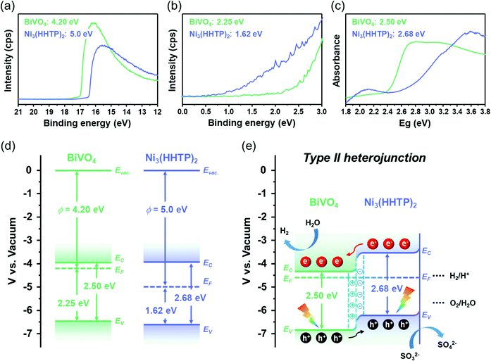
To reveal the dynamics of light absorption, charge separation, and charge transfer, the intrinsic band structures of BiVO4 and Ni3(HHTP)2 were investigated using ultraviolet photoelectron spectroscopy (UPS) and ultraviolet-visible (UV-vis) spectroscopy. Fig. 4a and b show the UPS of BiVO4 and Ni3(HHTP)2 for obtaining the work function (ϕ, energy from vacuum level to Fermi level) and valence band maximum (VBM, energy from Fermi level to valence band maximum). The work functions of BiVO4 and Ni3(HHTP)2 are 4.20 eV and 5.0 eV, while the VBM values are 2.25 eV and 1.62 eV, respectively. The UV-vis spectra in Fig. 4c shows that the energy bandgaps of BiVO4 and Ni3(HHTP)2 were 2.50 and 2.68 eV, respectively. The intrinsic band structures of BiVO4 and Ni3(HHTP)2 are shown in Fig. 4d. As BiVO4 has a higher EF than Ni3(HHTP)2, the electrons would transfer from BiVO4 to Ni3(HHTP)2 until equilibrium is reached. After the electronic state reached equilibrium, the band structure caused the upward band edge bending of BiVO4, and downward band edge bending of Ni3(HHTP)2, forming a type-II heterojunction. In the type-II heterojunction established in BiVO4/Ni3(HHTP)2, the photogenerated electrons migrated from the conduction band (EC) of Ni3(HHTP)2 to the EC of BiVO4. In contrast, the photogenerated holes migrated from the valence band (EV) of BiVO4 to the EV of Ni3(HHTP)2, facilitating the separation of photogenerated charge carriers (Fig. 4e). In addition, the intrinsic band structures of Co3(HHTP)2 and Cu3(HHTP)2 were investigated to understand the band-bending between BiVO4/Co3(HHTP)2 and BiVO4/Cu3(HHTP)2 (Fig. S14 and S15, ESI†). Both BiVO4/Co3(HHTP)2 and BiVO4/Cu3(HHTP)2 achieved the type-II heterojunction after reaching equilibrium. The band-bending structure is in line with the photoelectrochemical activities, indicating that the coating with HHTP-based MOFs promotes effective charge separation for the efficient photoelectrochemical performance of BiVO4. The results validate the high versatility of HHTP-based MOFs along with the enhanced photoelectrochemical activities of BiVO4/HHTP-based MOF heterostructure photoanodes.
Aside from band-bending diagrams of BiVO4/Ni3(HHTP)2, it is crucial to examine the three critical factors affecting the photoelectrochemical activity: light absorption efficiency (ηabs), charge separation efficiency (ηsep), and charge transfer efficiency (ηtrans). The three factors are expressed in the following water oxidation equation:37–39
| Jwater = Jmax × ηabs × ηsep × ηtrans | (2) |
| Jsulfite = Jmax × ηabs × ηsep | (3) |
If it is assumed that all the absorbed photons are fully converted to photocurrent density, the ηsep and ηtrans can be neglected. The equation can be further simplified as follows:
| Jabs = Jmax × ηabs | (4) |
![[thin space (1/6-em)]](https://www.rsc.org/images/entities/char_2009.gif) 000 s at 1.23 V vs. RHE (Fig. S17, ESI†). No severe degradation was observed, and the results indicate that BiVO4/Ni3(HHTP)2 was electrochemically stable over a long period. In addition, the structure of BiVO4/Ni3(HHTP)2 after photoelectrochemical reactions was observed by TEM and elemental mappings (Fig. S18, ESI†). The adhesion between BiVO4 and Ni3(HHTP)2 was strong enough to maintain its stable structure even after photoelectrochemical reactions.
000 s at 1.23 V vs. RHE (Fig. S17, ESI†). No severe degradation was observed, and the results indicate that BiVO4/Ni3(HHTP)2 was electrochemically stable over a long period. In addition, the structure of BiVO4/Ni3(HHTP)2 after photoelectrochemical reactions was observed by TEM and elemental mappings (Fig. S18, ESI†). The adhesion between BiVO4 and Ni3(HHTP)2 was strong enough to maintain its stable structure even after photoelectrochemical reactions.
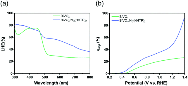 | ||
| Fig. 5 (a) Light harvesting efficiency (LHE) (%) and (b) charge separation efficiency (ηsep) of BiVO4 and BiVO4/Ni3(HHTP)2. | ||
Conclusions
BiVO4/M3(HHTP)2 heterojunction photoanodes with three different metal ions (M = Ni, Co, and Cu) were prepared via facile electrodeposition followed by a solvothermal process for photoelectrochemical reactions. The M3(HHTP)2 coating is aimed at improving the sluggish charge transport kinetics of BiVO4 by forming staggered band alignments. All three BiVO4/M3(HHTP)2 photoanodes exhibited higher photocurrent densities than the pristine BiVO4 film; type-II heterojunctions were observed between BiVO4 and M3(HHTP)2. Effective light absorption and charge separation were achieved through the type-II heterojunctions, which were confirmed by UPS and UV-vis spectroscopy. In particular, BiVO4/Ni3(HHTP)2 had the highest photocurrent density of 4.66 mA cm−2, which is 3.2 times greater than that of pristine BiVO4. Among the three types of M3(HHTP)2, Ni3(HHTP)2 exhibited the highest bulk conductivity, indicating that the electrical conductivity of MOF and the type-II band alignment significantly influenced the photoelectrochemical performance. This study demonstrates that establishing a type-II heterojunction between semiconducting M3(HHTP)2 and BiVO4 is a promising and general strategy for obtaining high-performance photoanodes.Conflicts of interest
There are no conflicts to declare.Acknowledgements
This work was supported by a grant from the Korea Environmental Industry & Technology Institute (No. 2020002700011).Notes and references
- Y. Li, L. Zhang, X. Xiang, D. Yan and F. Li, J. Mater. Chem. A, 2014, 2, 13250–13258 RSC.
- X. Cao, Y. Wang, J. Lin and Y. Ding, J. Mater. Chem. A, 2019, 7, 6294–6303 RSC.
- F. F. Abdi, T. J. Savenije, M. M. May, B. Dam and R. van de Krol, J. Phys. Chem. Lett., 2013, 4, 2752–2757 CrossRef CAS.
- L. Luo, Z.-j. Wang, X. Xiang, D. Yan and J. Ye, ACS Catal., 2020, 10, 4906–4913 CrossRef CAS.
- Z. Zhou, J. Chen, Q. Wang, X. Jiang and Y. Shen, Chin. J. Catal., 2022, 43, 433–441 CrossRef CAS.
- Z. Wang, Z. Lin, S. Shen, W. Zhong and S. Cao, Chin. J. Catal., 2021, 42, 710–730 CrossRef CAS.
- Y. Tang, R. Wang, Y. Yang, D. Yan and X. Xiang, ACS Appl. Mater. Interfaces, 2016, 8, 19446–19455 CrossRef CAS PubMed.
- W. He, R. Wang, L. Zhang, J. Zhu, X. Xiang and F. Li, J. Mater. Chem. A, 2015, 3, 17977–17982 RSC.
- J. M. Lee, J. H. Baek, T. M. Gill, X. Shi, S. Lee, I. S. Cho, H. S. Jung and X. Zheng, J. Mater. Chem. A, 2019, 7, 9019–9024 RSC.
- J. Z. Su, L. J. Guo, N. Z. Bao and C. A. Grimes, Nano Lett., 2011, 11, 1928–1933 CrossRef CAS PubMed.
- M. Z. Xie, X. D. Fu, L. Q. Jing, P. Luan, Y. J. Feng and H. G. Fu, Adv. Energy Mater., 2014, 4, 1300995 CrossRef.
- Q. G. Pan, C. Zhang, Y. J. Xiong, Q. X. Mi, D. D. Li, L. L. Zou, Q. H. Huang, Z. Q. Zou and H. Yang, ACS Sustainable Chem. Eng., 2018, 6, 6378–6387 CrossRef CAS.
- S. Q. Zhou, K. Y. Chen, J. W. Huang, L. Wang, M. Y. Zhang, B. Bai, H. Liu and Q. Z. Wang, Appl. Catal., B, 2020, 266, 118513 CrossRef CAS.
- G. X. Liu, Y. P. Li, Y. Xiao, D. M. Jia, C. H. Li, J. J. Zheng and X. W. Liu, Catal. Lett., 2019, 149, 870–875 CrossRef CAS.
- C. H. Liu, H. Luo, Y. Xu, Z. H. Zhang, Q. Liang, W. C. Wang and Z. D. Chen, Chem. Eng. J., 2020, 384, 123333 CrossRef CAS.
- J. W. Yoon, J. H. Kim, C. Kim, H. W. Jang and J. H. Lee, Adv. Energy Mater., 2021, 11, 2003052 CrossRef CAS.
- T. Y. Chen, J. H. Dou, L. M. Yang, C. Y. Sun, N. J. Libretto, G. Skorupskii, J. T. Miller and M. Dinca, J. Am. Chem. Soc., 2020, 142, 12367–12373 CrossRef CAS PubMed.
- J. H. Kim, D. H. Kim, J. W. Yoon, Z. F. Dai and J. H. Lee, ACS Appl. Energy Mater., 2019, 2, 4535–4543 CrossRef CAS.
- J. A. Seabold and K. S. Choi, J. Am. Chem. Soc., 2012, 134, 2186–2192 CrossRef CAS PubMed.
- Y. Nonoguchi, D. Sato and T. Kawai, Polymers, 2018, 10, 962 CrossRef PubMed.
- K. W. Nam, S. S. Park, R. dos Reis, V. P. Dravid, H. Kim, C. A. Mirkin and J. F. Stoddart, Nat. Commun., 2019, 10, 4948 CrossRef PubMed.
- W. H. Li, J. Q. Lv, Q. H. Li, J. F. Xie, N. Ogiwara, Y. Y. Huang, H. J. Jiang, H. Kitagawa, G. Xu and Y. B. Wang, J. Mater. Chem. A, 2019, 7, 10431–10438 RSC.
- S. C. Wang, P. Chen, Y. Bai, J. H. Yun, G. Liu and L. Z. Wang, Adv. Mater., 2018, 30, 1800486 CrossRef PubMed.
- Q. Qin, Q. Cai, W. T. Hong, C. Y. Jian and W. Liu, Chem. Eng. J., 2020, 402, 126227 CrossRef CAS.
- M. Fang, Q. A. Cai, Q. Qin, W. T. Hong and W. Liu, Chem. Eng. J., 2021, 421, 127796 CrossRef CAS.
- J. Li, F. Li and J. Jin, J. Power Sources, 2021, 482, 228957 CrossRef CAS.
- J. Jian, Y. Xu, X. Yang, W. Liu, M. Fu, H. Yu, F. Xu, F. Feng, L. Jia, D. Fredich, R. van de Krol and H. Wang, Nat. Commun., 2019, 10, 2609 CrossRef PubMed.
- Y. M. Jo, K. Lim, J. W. Yoon, Y. K. Jo, Y. K. Moon, H. W. Jang and J. H. Lee, ACS Cent. Sci., 2021, 7, 1176–1182 CrossRef CAS PubMed.
- L. S. Xie, G. Skorupskii and M. Dinca, Chem. Rev., 2020, 120, 8536–8580 CrossRef CAS PubMed.
- D. Sheberla, L. Sun, M. A. Blood-Forsythe, S. Er, C. R. Wade, C. K. Brozek, A. Aspuru-Guzik and M. Dinca, J. Mater. Chem. A, 2014, 136, 8859–8862 CAS.
- M. Hmadeh, Z. Lu, Z. Liu, F. Gandara, H. Furukawa, S. Wan, V. Augustyn, R. Chang, L. Liao, F. Zhou, E. Perre, V. Ozolins, K. Suenaga, X. F. Duan, B. Dunn, Y. Yamamto, O. Terasaki and O. M. Yaghi, Chem. Mater., 2012, 24, 3511–3513 CrossRef CAS.
- R. Dong, P. Han, H. Arora, M. Ballabio, M. Karakus, Z. Zhang, C. Shekhar, P. Adler, P. S. Petkov, A. Erbe, S. C. B. Mannsfeld, C. Felser, T. Heine, M. Bonn, X. L. Feng and E. Canovas, Nat. Mater., 2018, 17, 1027 CrossRef CAS PubMed.
- X. Huang, P. Sheng, Z. Y. Tu, F. J. Zhang, J. H. Wang, H. Geng, Y. Zou, C. A. Di, Y. P. Yi, Y. M. Sun, W. Xu and D. B. Zhu, Nat. Commun., 2015, 6, 7408 CrossRef CAS PubMed.
- A. H. Wilson, Proc. R. Soc. London, 1938, 167, 0580–0593 CAS.
- M. L. O. Ne, M. Boujnah, A. Benyoussef and A. El Kenz, J. Supercond. Novel Magn., 2017, 30, 1263–1267 CrossRef.
- M. E. Foster, K. Sohlberg, C. D. Spataru and M. D. Allendorf, J. Phys. Chem. C, 2016, 120, 15001–15008 CrossRef CAS.
- H. Dotan, K. Sivula, M. Gratzel, A. Rothschild and S. C. Warren, Energy Environ. Sci., 2011, 4, 958–964 RSC.
- D. K. Zhong, S. Choi and D. R. Gamelin, J. Am. Chem. Soc., 2011, 133, 18370–18377 CrossRef CAS PubMed.
- P. M. Rao, L. L. Cai, C. Liu, I. S. Cho, C. H. Lee, J. M. Weisse, P. D. Yang and X. L. Zheng, Nano Lett., 2014, 14, 1099–1105 CrossRef CAS PubMed.
Footnote |
| † Electronic supplementary information (ESI) available. See DOI: 10.1039/d2ya00008c |
| This journal is © The Royal Society of Chemistry 2022 |

