Controlling the magnetic anisotropy of RumIrn (m + n = 3) clusters using the MgO(001) substrate†
Qing
Diao
,
Chengwei
Yang
,
Honglei
Liu
,
Hongxia
Yan
,
Guixian
Ge
 *,
Xiaodong
Yang
* and
Jueming
Yang
*
Key Laboratory of Ecophysics and Department of Physics, College of Science, Shihezi University, Shihezi, 832003, P. R. China. E-mail: geguixian@126.com; yangxiaodong1209@hotmail.com; juemingyang11@gmail.com
First published on 1st December 2022
Abstract
Large perpendicular magnetic anisotropy energy (MAE) and flexible regulation of the magnitude and direction of MAE have great potential for application in information storage devices. Here, utilizing first-principles calculations, we investigated the magnetic properties of free and MgO(001) supported RumIrn clusters (RumIrn@MgO(m + n = 3)). The results indicate that the MAE of mixed clusters increases with the number of Ir atoms due to Ir having a strong coupling between the non-degenerate dxy and dx2−y2 states. The MAE of free Ir3 is −8.18 meV with the easy magnetization direction parallel to the x-axis, while the MAE of supported Ir3 on the MgO substrate increases by a factor of 2.6, and the easy magnetization axis of the structure is shifted to a direction perpendicular to the substrate surface. This change in MAE is due to the significant enhancement in the coupling between the non-degenerate dyz and dx2−y2 states near the Fermi level of Ir3 atoms. Moreover, Ir3@MgO possesses high thermodynamic stability. These results give a new method for manipulating MAE and the direction of easy magnetization, which has great potential for application in magnetic nanodevices.
Introduction
In conventional electronics, the charge properties of electrons or holes are used to transmit and process information, and the spin properties of the polarized electrons in magnetic materials are used to store the information.1,2 The most critical point for high-density magnetic storage applications in reality is to explore materials with a large perpendicular magnetic anisotropy (PMA) to resist thermal perturbations so that the information will not be lost.3 Magnetic anisotropy mainly results from the spin–orbit coupling (SOC) interactions, a combination of the orbital magnetic moments and the coordination field. Strong SOC and large spin and orbital magnetic moments will lead to large magnetic anisotropy energy (MAE).4–8 The mixed clusters of 4d and 5d transition metals (TMs) may have large MAE due to the strong SOC and large spin moments of TMs.9–14A supporting substrate may be necessary for the actual device realization of clusters, and large PMA is highly desirable for realizing atomic-scale magnetic data storage.15,16 Nonmagnetic 2D materials are an active interdisciplinary research topic to support clusters for spintronics and nanoscience applications due to the appropriate ligand field they provide.14,17–19 Xing et al. studied the MAE of the transition metal dimer supported by benzene (BZ) and found that the MAEs of OsRu@BZ and IrRh@BZ were about 58 meV and 72 meV, respectively.14 The MAEs of graphene supported mixed clusters of 4d and 5d TM with a single vacancy defect (SV), a single nitrogen-decorated vacancy defect (NSV), and a double nitrogen-decorated vacancy defect (NDV) have been extensively studied.20–22 Compared with the substrates mentioned above, the MgO(001) surface provides a unique ligand field and degenerate levels induced by the orbital multiplet effects.23–27 For instance, the orbital multiplicity effect leads to degenerate levels and then produces a huge MAE (60 meV) of Co@MgO(001) due to the special tetragonal ligand field of MgO(001).28 And, thus MgO(001) may be a suitable substrate for supporting clusters to obtain a large MAE. What is more, studies have pointed out that the MAE of Co@MgO(001) is 6 times larger than that of a single Co atom on the surface of Pt(111).29 If Co is replaced by a Ru atom with stronger SOC, the MAE of Ru@MgO(001) reaches 110 meV/Ru.30 Although the magnetic properties of mixed dimers with 4d-TM and 5d-TM have been widely studied, the magnetic properties of TM trimers with 4d and 5d have not been reported. Hence, the research on the MAE of the RumIrn trimers supported using the MgO(001) substrate has important practical and theoretical significance.
In this work, we investigated the magnetic properties of free RumIrn (m + n = 3) clusters and manipulated the magnetic anisotropy of RumIrn using the MgO(001) substrate employing first-principles calculations. The results show that RuIr2 has a large MAE of 23.40 meV and Ir atoms contribute most to the MAE of mixed RumIrn. The MgO substrate increases the projected density of states (PDOS) of RumIrn clusters, leading the MAE of Ir3@MgO to increase by a factor of 2.6 and regulating the easy magnetized axis from axial to out-of-plane. These changes result from a large enhancement of the mutual coupling between the non-degenerate d-orbits of dyz and dx2−y2 states. This regulation of the magnitude and direction of the MAE provides new ideas for the future applications of materials in magnetic storage.
Computational details
Density functional theory (DFT) computations were carried out in the VASP31 code using the projector augmented-plane wave (PAW)32 method. Perdew, Burke, and Ernzerhof (PBE) exchange–correlation functionals in the generalized gradient approximation (GGA)33 was used to model the interaction between ions and electrons. 500 eV was chosen as the plane wave cut-off energy. A 4 × 4 × 1 Brillouin zone k-point grid was used for structural optimization, and 6 × 6 × 1 for static and MAE calculations. The MAE was calculated taking the SOC into consideration. The convergence criteria for force and total energy were 1 × 10⁻² eV Å−1 and 1 × 10⁻⁷ eV, respectively. We constructed a 4 × 4 rectangular supercell of MgO(001) with a lattice constant of 8.4918 Å. To prevent effects between periodic lattices, we added a vacuum layer of 17 Å in the direction perpendicular to the substrate. To consider the Coulomb interaction, we used a method of GGA+U with U–J values of 2.3–2.5 eV for 4d and 5d states to describe the d electrons.34,35 To verify the rationality of the selected Ueff (U–J) value, we tested the Ueff value as shown in Tables S1 and S2 (ESI†). The results suggest that the MAEs of these systems have a minor change in the Ueff values of 1.92–2.92 eV for Ru and 1.84–2.84 eV for Ir. In addition, the MS value remains constant with a Ueff of 1.92–2.92 for Ru. Therefore, the used Ueff values for Ru and Ir of 2.42 and 2.34 eV, respectively, in our calculations are reasonable. The MAE is defined by this formula: MAE = Ex − Ez, where Ex and Ez represent the total energies of self-consistent calculations in the x (in-plane) and z (vertical) magnetization directions, respectively.Results and discussion
Geometry and stability of RumIrn and RumIrn@MgO (m + n = 3)
The lowest energy structures of RumIrn are shown in Fig. 1. The lowest energy structures of Ru3 and Ru2Ir are near the isosceles triangle. The lengths of isosceles sides of Ru3 (2.235 Å) are shorter than those of the Ru–Ir bond of Ru2Ir (2.392 Å), while the Ru–Ru bond of Ru3 is longer than the based side of Ru2Ir (2.178 Å). The lowest energy structure of RuIr2 is still an isosceles triangle, while the Ru–Ir bond length of RuIr2 is slightly smaller than that of Ru2Ir. When all Ru atoms are replaced, the lowest energy structure of Ir3 is linear, with the smallest bond length (2.180 Å) in the clusters of RumIrn.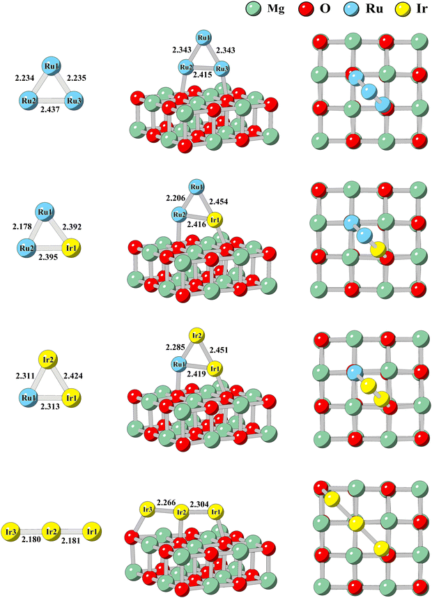 | ||
| Fig. 1 The lowest energy structures of RumIrn clusters and RumIrn@MgO systems (m + n = 3). The red and green balls represent Mg atoms and O atoms, respectively. The bond length is in angstrom (Å). | ||
To further explore the influence of different components on the stability of clusters, we calculated the binding energy (Eb) of a cluster with the following formula:
| Eb = ERumIrn − mERu − nEIr | (3-1) |
| Cluster | Ru3 | Ru2Ir | RuIr2 | Ir3 |
|---|---|---|---|---|
| M S (μB) | 6.00 | 5.00 | 4.00 | 1.00 |
| E b (eV) | −11.75 | −11.32 | −10.56 | −10.05 |
| MAE (meV) | −4.39 | 4.07 | 23.40 | −8.18 |
To elucidate the charge transfer of RumIrn, Table 2 demonstrates the Bader charge (Q) of each atom in RumIrn, respectively. For Ru2Ir, the charge of Ir is 0.296 e, indicating that 0.296 electrons transfer from Ir to Ru. The charge of the Ru atom in RuIr2 is −0.274 e. The transfer charge of atoms in Ru3 is quite small. While for Ir3, the charge of Ir2 reached −0.323 e, and thus the Ir–Ir bond is the smallest with 2.181 Å among all the studied RumIrn clusters. The Bader charge analysis demonstrates that the capacity to obtain electrons of Ru is substantially greater than that of Ir.
| Q (e) | Ru1 | Ru2 | Ru3 | Ir1 | Ir2 | Ir3 | RumIrn |
|---|---|---|---|---|---|---|---|
| Ru3 | −0.053 | 0.022 | 0.030 | — | — | — | 0 |
| Ru2Ir | −0.142 | −0.154 | — | 0.296 | — | — | 0 |
| RuIr2 | −0.274 | — | — | 0.149 | 0.125 | — | 0 |
| Ir3 | — | — | — | 0.145 | −0.323 | 0.178 | 0 |
| Ru3@MgO | 0.086 | 0.091 | 0.097 | — | — | — | 0.274 |
| Ru2Ir@MgO | −0.009 | −0.076 | — | 0.442 | — | — | 0.358 |
| RuIr2@MgO | −0.262 | — | — | 0.411 | 0.264 | — | 0.413 |
| Ir3@MgO | — | — | — | 0.343 | −0.013 | 0.412 | 0.742 |
The lowest energy structures and the sub-stable structure of RumIrn@MgO are also shown in Fig. 1 and Fig. S1 of the ESI,† respectively. The lowest energy structures of RumIrn@MgO are the Ru or Ir atoms situated on top of the O atom. The effect of the substrate on the structure of clusters is minimal, and the relative changes in the bond lengths of RumIrn do not surpass 4.6% except for Ir3. Ir atoms at both ends of Ir3 are attracted to O atoms, resulting in an increase in the length of the Ir–Ir bond. The minimum distance (d) between Ru/Ir and the nearest O of the substrate ranges from 2.07 Å to 2.18 Å (see Table 3), showing a strong binding between the MgO substrate and clusters.
| Structure | Ru3@MgO | Ru2Ir@MgO | RuIr2@MgO | Ir3@MgO |
|---|---|---|---|---|
| d (Å) | 2.18 | 2.11 | 2.07 | 2.12 |
| E A (eV) | −1.91 | −2.27 | −2.80 | −2.31 |
| MAE (meV) | −2.86 | 3.93 | 4.18 | 20.56 |
To evaluate the stability of RumIrn supported by the MgO substrate, the adsorption energy EA (see Table 3) is calculated using the following equation:
| EA = ERumIrn@MgO − ERumIrn − EMgO | (3-2) |
To clarify the physical essence of RumIrn firmly anchored on the MgO substrate, we performed the Bader charge analysis of RumIrn@MgO (see Table 2). As displayed in Table 2, Ru3 supported by MgO loses the least number of electrons (0.274 e) among the RumIrn@MgO systems, and the number of lost electrons for RumIrn gradually increases with the increasing Ir atom. The total charge reaches 0.742 e in Ir3@MgO, suggesting that Ir3 interacts strongly with the substrate. Compared with the charge of free clusters, the MgO support induces clusters to transfer more electrons to the substrate.
To further investigate the interaction between RumIrn and the MgO substrate, we show the differential charge density of RumIrn@MgO in Fig. 2. The light yellow and blue areas represent charge accumulation and dissipation, respectively. It is clear that oxygen atoms mainly obtain electrons for the MgO substrate. All the differential charge densities show that the O atoms near the Ir atoms lose more charge than the O atoms near the Ru atoms, indicating that the Ir atoms have a stronger interaction with the MgO substrate.
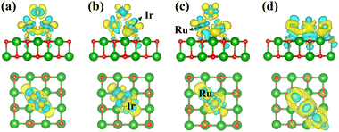 | ||
| Fig. 2 Top and side views of the differential charge density of (a) Ru3@MgO, (b) Ru2Ir@MgO, (c) RuIr2@MgO, and (d) Ir3@MgO, respectively. | ||
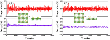
We further conducted the stability analysis of support systems using an ab initio molecular dynamics simulation (MDS) at 300 K, taking RuIr2@MgO and Ir3@MgO as examples. The thermodynamic stability of RuIr2@MgO and Ir3@MgO was evaluated by 10 ps using a Nose–Hoover thermostat with a step of 1 fs, and the canonical ensemble was employed. As shown in Fig. 3, the structures of the two systems do not change significantly after huge temperature fluctuations, and the energy fluctuations are minor, indicating their high thermodynamic stability.
Magnetic properties of RumIrn and RumIrn@MgO (m + n = 3)
The total spin moments MS (the total spin moment of a unit cell) of RumIrn are given in Table 1. The MS of RumIrn decreases with the number of Ru atoms, where Ru3 has the largest (6 μB), and Ir3 has the smallest (1 μB) spin magnetic moment among all the studied RumIrn clusters. Furthermore, we listed the MAEs of clusters in Table 1. Ru3 exhibits an MAE of −4.39 meV with an easy magnetization axis parallel to the triangle plane. Ru2Ir has a small MAE (4.07 meV) with an easy magnetization axis perpendicular to the triangle plane. RuIr2 presents a maximum MAE (23.40 meV) with the same easy magnetization direction as that of Ru2Ir. For Ir3, the easy magnetization axis parallels the x-axis with an MAE of −8.18 meV. Single component clusters exhibit in-plane or axial magnetic anisotropy, while mixed clusters with different Ru and Ir elements produce the perpendicular magnetic anisotropy.To better understand the physical picture of the effect of different components on the MAE of clusters, the projected density of states (PDOS) of the d-orbital of free RumIrn is illustrated in Fig. 4. Following the second-order perturbation formula,36 the distribution of the d-orbits near the Fermi level affects the magnitude of MAE. The second-order perturbation formula is as follows:
 | (3-3) |
 . As eqn (3-3), the main contribution to MAE is derived from the states near the Fermi level. In the following analysis, the matrix element difference |〈o↑/↓|u↑/↓〉|2 corresponds to the orbital–momentum matrix element squared difference
  in eqn (3-3).
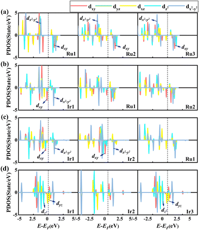 | ||
| Fig. 4 Projected density of states of the d-orbital of each atom in (a) Ru3, (b) Ru2Ir, (c) RuIr2, and (d) Ir3 without SOC. | ||
As shown in Fig. 4, the 5-fold degenerate d states of all atoms in RumIrn are split into three non-degenerate states (dxy, dz2, and dx2−y2) and two 2-fold degenerate states (dyz and dxz). The MAEs of clusters are mainly from the spin-down occupied and unoccupied states except for Ru3. For Ru3, the non-zero matrix elements |〈dx2−y2↑|dxy↓〉|2 of the three Ru atoms have the main contribution, leading to an in-plane MAE (as shown in Fig. 4(a)). The non-zero matrix element |〈dxy↓|dx2−y2↓〉|2 of the Ir1 atom dominates the out-of-plane MAE of Ru2Ir (as shown in Fig. 4(b)). The MAE of RuIr2 is still largely donated by the non-zero matrix element |〈dxy↓|dx2−y2↓〉|2 of Ir1 (see Fig. 4(c)), but Ir2 also contributes positively to MAE, resulting in a large out-of-plane MAE with 23.40 meV. For the MAE of Ir3, it is mainly contributed by the non-zero matrix elements |〈dz2↓|dyz↓〉|2 of Ir1 and Ir3, leading to the axial MAE of −8.18 meV (see Fig. 4(d)). The MAE of Ir3 is larger than that of Ru3. Meanwhile, Ir contributes most to the MAE of mixed clusters, indicating that Ir may bring large MAE, and the MAE can be increased by changing the composition of RumIrn.
To reveal the potential mechanism of how composition change impacts the MAE, the d-orbital resolved MAE of RumIrn with the SOC effect is analyzed according to the method of second-order perturbation theory.37Fig. 5 shows the d-orbital resolved MAE of each atom in RumIrn. As shown in Fig. 5(a), the matrix elements (dxy, dx2−y2) of three Ru atoms play a dominant role in the MAE of Ru3, while their contributions are extremely small, resulting in a minute in-plane MAE (−4.39 meV). For Ru2Ir, the MAE is largely contributed by the matrix element (dxy, dx2−y2) of Ir1, while the coupling between the dxy and dx2−y2 states of Ru2 gives a negative contribution, which leads to a small out-of-plane MAE (4.07 meV). For RuIr2, as shown in Fig. 5(c), the positive contribution is mainly from the matrix elements (dxy, dx2−y2) of Ir1 and Ir2, which leads to a large out-of-plane MAE (23.40 meV). The MAE of Ir3 is mainly contributed by the matrix elements (dz2, dyz) of Ir1 and Ir3, resulting in an MAE of −8.18 meV with the easy axis parallel to the Ir–Ir bond.
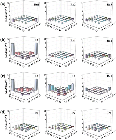 | ||
| Fig. 5 The d-orbital resolved MAE of each atom in the (a) Ru3, (b) Ru2Ir, (c) RuIr2, and (d) Ir3 clusters, respectively. | ||
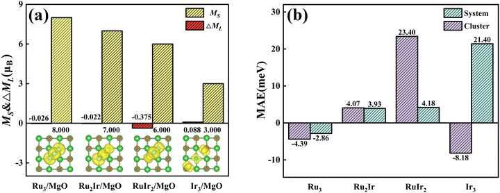
For the RumIrn@MgO systems, we investigated the total spin moment MS as shown in Fig. 6(a). Ir3@MgO possesses a large spin moment (3.00 μB). Compared with RumIrn, all the MS values of RumIrn@MgO increased by 2 μB, respectively. According to the Bader charge analysis, the oxygen atoms in the substrate obtain electrons from RumIrn, which increases the number of unpaired electrons in RumIrn and leads to the increment in MS. To investigate the origin of the magnetic moment, we presented the spin densities in the inserted figure of Fig. 6(a). It can see that the spin densities of RumIrn@MgO are mainly located on the RumIrn clusters, suggesting that the RumIrn clusters contribute to the major magnetic moment.
To reveal the regulatory effect of the support on the MAE, we listed the MAEs of free and supported RumIrn as shown in Fig. 6(b). Compared with free clusters, the MAEs of Ru3@MgO and Ru2Ir@MgO change little. However, the MAE of RuIr2@MgO changes a lot and decreases to 4.18 meV, and the easy magnetization axis remains unchanged. In comparison, the MAE of Ir3@MgO (21.40 meV) increases to more than twice the original and the easy magnetization axis changes from in-plane to out-of-plane. Such changes provide a guidance for the regulation of MAE. To investigate the origin of MAE, we give the orbital magnetic moment difference (ΔML = ML‖ − ML⊥) as shown in Fig. 6(a). As prescribed by Bruno's relationship,38 ΔML and MAE follow a linear relationship according to the formula  , where
  is the effective coefficient to represent the interactions between spins and orbitals. The MAE and ΔML of RumIrn@MgO largely follow Bruno's relationship, and Ir3@MgO has a large ΔML (0.088 μB) and the largest MAE of 21.40 meV.
For free RumIrn, the dx2−y2 and dxy states of Ir move to a high and low energy level with the number of Ru atoms decreasing, respectively, as shown in Fig. 4. When clusters are placed on the surface of MgO, the O atoms mainly obtain electrons and lead to redistribution of electrons for RumIrn clusters. One can find that the lost electrons of Ir increase and the bond of Ir–O changes from a covalent bond to an ionic bond with the decreasing number of Ru atoms, which cause the dx2−y2 and the occupied dxz(yz) states of Ir shift to a low energy level and a high energy level, respectively, as displayed in Table 2 and Fig. 2. The above analyses indicate that Ru atoms and the MgO substrate can cause the redistribution of states near the Fermi level, which leads to the change of MAE.
Next, we studied the PDOS of the d-orbital of RumIrn@MgO in Fig. 7 to analyze the origin of MAE. Similar to the PDOS of RumIrn, the 5-fold degenerate d-states of RumIrn atoms in RumIrn@MgO are split into three non-degenerate states (dxy, dz2, and dx2−y2) and two 2-fold degenerate states (dyz and dxz). As shown in Fig. 7(a), for Ru3@MgO, the non-zero matrix elements |〈dxy↑|dx2−y2↓〉|2 and |〈dxy↓|dx2−y2↓〉|2 of Ru1 have the main and opposite contributions to the MAE, resulting in the small in-plane MAE (−2.86 meV). For Ru2Ir@MgO, the non-zero matrix element |〈dyz↑|dz2↓〉|2 of Ir1 contributes mainly to the out-of-plane MAE of 3.93 meV (see Fig. 7(b)). The non-zero matrix element |〈dxy↑|dx2−y2↓〉|2 of Ir1 has a negative contribution to the MAE of RuIr2@MgO, while the non-zero matrix elements |〈dxy↓|dx2−y2↓〉|2 and |〈dz2↓|dyz↓〉|2 of Ir2 positively contribute to the MAE of RuIr2@MgO, resulting in an out-of-plane MAE of 4.18 meV (see Fig. 7(c)). For Ir3@MgO (see Fig. 7(d)), its MAE is mainly contributed by the non-zero matrix element |〈dyz↑|dx2−y2↓〉|2 of Ir1 and Ir2, resulting in a large out-of-plane MAE (20.56 meV).
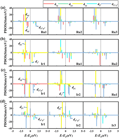 | ||
| Fig. 7 Spin-polarized PDOS of the d-orbital of each atom in RumIrn (m + n = 3), leaving out the SOC effect of (a) Ru3@MgO, (b) Ru2Ir@MgO, (c) RuIr2@MgO, and (d) Ir3@MgO, respectively. | ||
To elucidate the physical picture behind the impact of the MgO substrate, the d-orbital resolved MAE of RumIrn@MgO with the SOC effect is shown in Fig. 8. For the Ru3@MgO system, as shown in Fig. 8(a), the contribution to MAE is mainly from the matrix element (dxy, dx2−y2) of Ru1, resulting in a small in-plane MAE (−2.86 meV). As shown in Fig. 8(b), for Ru2Ir@MgO, the matrix element (dz2, dyz) of Ir1 has a relatively large positive contribution, resulting in an out-of-plane MAE of 3.93 meV. For RuIr2@MgO, MAE is mainly contributed by the matrix elements (dxy, dx2−y2) and (dz2, dyz) of Ir2, but the negative contribution of the matrix element (dxy, dx2−y2) of Ir1 is large, resulting in a small out-of-plane MAE (4.18 meV). In Fig. 8(d), the matrix elements (dyz, dx2−y2) of all Ir atoms in Ir3@MgO give the main positive contribution, resulting in a large out-of-plane MAE (20.56 meV).
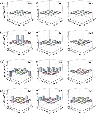 | ||
| Fig. 8 The d-orbital resolved MAE of (a) Ru3@MgO, (b) Ru2Ir@MgO, (c) RuIr2@MgO, and (d) Ir3@MgO systems, respectively. | ||
To better comprehend the influence of the substrate on the MAE, the PDOS diagrams of the d-orbital of RumIrn and RumIrn@MgO (n = 2, 3) are shown in Fig. 9 due to the MAEs of RuIr2 and Ir3 greatly change after being supported on the MgO substrate. As shown in Fig. 9(a), the nonzero matrix elements |〈dx2−y2↑|dxy↓〉|2 and |〈dxy↑|dx2−y2↓〉|2 of free RuIr2 are the main contributors to the MAE. After being supported, the occupied states of dyz and dxz increase significantly, and then the main contribution to the MAE is from the nonzero matrix element |〈dyz↑|dz2↓〉|2. Hence, the MAE of RuIr2@MgO drastically reduce after being supported, and the easy magnetization axis direction remains unchanged (see Fig. 9(b)). For free Ir3, the occupied spin-down dz2 states are closer to the Fermi level than the occupied spin-up dz2 states, so the non-zero matrix elements |〈dz2↓|dyz↓〉|2 give major contributions to the MAE, resulting in an in-plane MAE of −8.18 meV (see Fig. 9(c)). After being supported, the occupied spin-up dxz state increases greatly, which leads to the contribution to the MAE (20.56 meV) mainly from the non-zero matrix element |〈dyz↑|dx2−y2↓〉|2 of Ir3 (as shown in Fig. 9(d)), and the change of the easily magnetized axis from in-plane to out-of-plane.
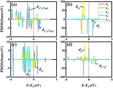 | ||
| Fig. 9 The PDOS of the d-orbital of RumIrn (m + n = 3) irrespective of the SOC effect of the (a) RuIr2, (b) RuIr2@MgO, (c) Ir3, and (d) Ir3@MgO systems. | ||
To better understand the underlying mechanism of the effect of the substrate, the total d-orbital resolved MAE images of RumIrn and RumIrn@MgO (n = 2, 3) are shown in Fig. 10. For RuIr2, the matrix element (dxy, dx2−y2) gives a large positive contribution, resulting in a large out-of-plane MAE (23.40 meV) (see Fig. 10(a)). As shown in Fig. 10(b), after being supported, the contribution of the matrix element (dxy, dx2−y2) of RuIr2 decreases resulting in a small out-of-plane MAE (4.18 meV). As shown in Fig. 10(c) and (d), free Ir3 is mainly negatively contributed by the matrix element (dz2, dyz), resulting in a small in-plane MAE (−8.18 meV). After being supported, the matrix element (dz2, dyz) of Ir3 has a positive contribution to the MAE, while the positive contribution from the matrix element (dyz, dx2−y2) increases significantly; hence, the magnitude of the MAE (20.56 meV) remarkably increases meanwhile the easily magnetized axis turns from in-plane to out-of-plane.
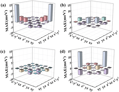 | ||
| Fig. 10 The total d-orbital resolved MAE of the TM atoms in (a) RuIr2, (b) RuIr2@MgO, (c) Ir3, and (d) Ir3@MgO. | ||
Conclusions
This paper investigated the magnetic anisotropy of RumIrn trimers and RumIrn@MgO systems (m + n = 3) and the modulatory effect of the MgO support on the MAE using first-principles calculations. Only Ru2Ir and RuIr2 produce a perpendicular magnetic anisotropy among trimers. The Ir atoms contribute most to the MAE of mixed RumIrn owing to the strong coupling between the non-degenerate dxy and dx2−y2 states of Ir. The magnitude of MAE and the easy magnetization direction of structures can be manipulated using the MgO support, which is attributed to the increase of the densities of states around the Fermi level of RumIrn. The free Ir3 exhibits a small in-plane MAE of −8.18 meV, while Ir3@MgO possesses high stability and a large perpendicular magnetic anisotropy with an MAE of 21.40 meV due to the strong coupling between the non-degenerate dyz and dx2−y2 states around the Fermi level of Ir3. This work provides an effective method for regulating the magnitude and direction of magnetic anisotropy to facilitate practical applications.Conflicts of interest
The authors declare that they have no known competing financial interests or personal relationships that could have appeared to influence the work reported in this paper.Acknowledgements
This work was supported by the National Natural Science Foundation of China (Grant No. 11764034 and 12064036), the Program for Changjiang Scholars and Innovative Research Team in University (No. IRT_15R46), the Yangtze River Scholar Research Project of Shihezi University (No. CJXZ201601), the Shihezi University Young Innovative Talents Cultivation Program (No. CXPY202114 and CXPY202019), and the High-level Talent Scientific Research Start-up Project (No. RCZK202008).References
-
A. Ehrmann and T. Blachowicz, in Chemical Solution Synthesis for Materials Design and Thin Film Device Applications, ed. S. Das and S. Dhara, Elsevier, 2021, pp. 665–677 Search PubMed
.
- M. Alamdar, T. Leonard, C. Cui, B. P. Rimal, L. Xue, O. G. Akinola, T. Patrick Xiao, J. S. Friedman, C. H. Bennett, M. J. Marinella and J. A. C. Incorvia, Appl. Phys. Lett., 2021, 118, 112401 CrossRef CAS
.
- F. Kalff, M. Rebergen, E. Fahrenfort, J. Girovsky, R. Toskovic, J. Lado, J. Fernández-Rossier and A. Otte, Nat. Nanotechnol., 2016, 11, 926–929 CrossRef CAS PubMed
.
- J.-Y. You, X.-J. Dong, B. Gu and G. Su, Phys. Rev. B, 2021, 103, 104403 CrossRef CAS
.
- H. L. Zhuang, P. R. C. Kent and R. G. Hennig, Phys. Rev. B, 2016, 93, 134407 CrossRef
.
- P. Ravindran, A. Kjekshus, H. Fjellvåg, P. James, L. Nordström, B. Johansson and O. Eriksson, Phys. Rev. B: Condens. Matter Mater. Phys., 2001, 63, 144409 CrossRef
.
- S. Jana, S. Chowdhury, D. Jana, A. Chakrabarti and A. Banerjee, J. Phys., 2021, 13 Search PubMed
.
- H. Yuan, Y. Chen, X. Wang, M. Zhong, T. Yang, P. Wang, M. Ju, H. Cui and H. Chen, Phys. Rev. Mater., 2021, 5, 024408 CrossRef CAS
.
- X.-Y. Wang, C. Avendaño and K. R. Dunbar, Chem. Soc. Rev., 2011, 40, 3213 RSC
.
- X. Fan, J. Jiang, R. Li and W. Mi, J. Phys. Chem. C, 2021, 125, 13688–13695 CrossRef CAS
.
- S. Jekal, A. Danilo, D. Phuong and X. Zheng, Appl. Sci., 2019, 9, 630 CrossRef CAS
.
- W. Ju and Z. Yang, Phys. Lett. A, 2012, 376, 1300–1305 CrossRef CAS
.
- D. Odkhuu, S. H. Rhim, N. Park and S. C. Hong, Phys. Rev. B: Condens. Matter Mater. Phys., 2013, 88, 184405 CrossRef
.
- J. Xing, X. Jiang, P. Wang and J. Zhao, Phys. Rev. Res., 2021, 3, 033005 CrossRef CAS
.
- M. Guo, X. Liang, H. Wang and J. Zhang, Phys. Chem. Chem. Phys., 2020, 22, 238–244 RSC
.
- J. Chen, H. Cui, P. Wang, Y. Zheng, D. Wang, H. Chen and H. Yuan, Phys. Chem. Chem. Phys., 2020, 22, 26155–26166 RSC
.
- M. Zhang, H. Guo, J. Lv, J. Jia and H. Wu, J. Magn. Magn. Mater., 2021, 533, 168026 CrossRef CAS
.
- W. Qiao, D. Jin, W. Mi, D. Wang, S. Yan, X. Xu and T. Zhou, arXiv, 2022, preprint, arXiv:2202.13726 DOI:10.48550/arXiv.2202.13726.
- D. Odkhuu, Phys. Rev. B, 2016, 94, 060403 CrossRef
.
- J. Hu and R. Wu, Nano Lett., 2014, 14, 1853–1858 CrossRef CAS PubMed
.
- J. Navrátil, M. Otyepka and P. Błoński, Nanotechnology, 2022, 33, 215001 CrossRef PubMed
.
- J. Navrátil, P. Błoński and M. Otyepka, Nanotechnology, 2021, 32, 230001 CrossRef PubMed
.
- X. Liu, X. Yang, J. Yang, P. Ge, H. Yan, J. Wan, G. Ge and G. Wang, Appl. Surf. Sci., 2021, 541, 148421 CrossRef CAS
.
- G. Yang, X. Liu, X. Zhai, Y. Zhang, H. Yan, X. Yang, L. Zhou, J. Yang and G. Ge, Phys. E, 2022, 136, 115039 CrossRef CAS
.
- W. Zhang, K. Chi, X. Feng, Y. Shi, Z. Li, Y. Xing, T. Zhou, H. Meng and B. Liu, J. Magn. Magn. Mater., 2021, 538, 168270 CrossRef CAS
.
- D. Odkhuu, Sci. Rep., 2018, 8, 1–9 CAS
.
- C. Wolf, F. Delgado, J. Reina and N. Lorente, J. Phys. Chem. A, 2020, 124, 2318–2327 CrossRef CAS PubMed
.
- I. G. Rau, S. Baumann, S. Rusponi, F. Donati, S. Stepanow, L. Gragnaniello, J. Dreiser, C. Piamonteze, F. Nolting, S. Gangopadhyay, O. R. Albertini, R. M. Macfarlane, C. P. Lutz, B. A. Jones, P. Gambardella, A. J. Heinrich and H. Brune, Science, 2014, 344, 988–992 CrossRef CAS PubMed
.
- T. Balashov, T. Schuh, A. F. Takács, A. Ernst, S. Ostanin, J. Henk, I. Mertig, P. Bruno, T. Miyamachi, S. Suga and W. Wulfhekel, Phys. Rev. Lett., 2009, 102, 257203 CrossRef CAS PubMed
.
- X. Ou, H. Wang, F. Fan, Z. Li and H. Wu, Phys. Rev. Lett., 2015, 115, 257201 CrossRef PubMed
.
- G. Kresse and J. Hafner, Phys. Rev. B: Condens. Matter Mater. Phys., 1993, 47, 558–561 CrossRef CAS PubMed
.
- P. E. Blöchl, Phys. Rev. B: Condens. Matter Mater. Phys., 1994, 50, 17953–17979 CrossRef PubMed
.
- J. P. Perdew, K. Burke and M. Ernzerhof, Phys. Rev. Lett., 1996, 77, 3865–3868 CrossRef CAS PubMed
.
- I. V. Solovyev, P. H. Dederichs and V. I. Anisimov, Phys. Rev. B: Condens. Matter Mater. Phys., 1994, 50, 16861–16871 CrossRef CAS PubMed
.
- T. Hamada and T. Ohno, J. Phys.: Condens. Matter, 2019, 31, 065501 CrossRef PubMed
.
- D. Wang, R. Wu and A. J. Freeman, Phys. Rev. B: Condens. Matter Mater. Phys., 1993, 47, 14932–14947 CrossRef CAS PubMed
.
- B. Dieny and M. Chshiev, Rev. Mod. Phys., 2017, 89, 025008 CrossRef
.
- P. Bruno, Phys. Rev. B: Condens. Matter Mater. Phys., 1989, 39, 865–868 CrossRef PubMed
.
Footnote |
| † Electronic supplementary information (ESI) available. See DOI: https://doi.org/10.1039/d2cp03760b |
| This journal is © the Owner Societies 2023 |

