 Open Access Article
Creative Commons Attribution 3.0 Unported Licence
The mechanism for N2 activation in the E4 – state of nitrogenase†
Per E. M.
Siegbahn

Department of Organic Chemistry, Arrhenius Laboratory, Stockholm University, SE-106 91, Stockholm, Sweden. E-mail: per.siegbahn@su.se
First published on 21st August 2023
Abstract
Nitrogenases take nitrogen from the air and reduce it to ammonia. It has long been known that N2 becomes activated after four reductions in the catalytic cycle, in the E4 state. Several mechanisms for the activation have been suggested. In the present study a previous mechanism has been revised based on recent experimental findings. In the present mechanism N2H2 is formed in E4. As in the previously suggested mechanism, there are four initial reductions before catalysis (the A-states), after which a sulfide is released and the first state in catalysis (E0) is formed. In E4, N2 becomes bound and protonated in the Fe1, Fe2, Fe4 region, in which the hydrides have left two electrons. The rate-limiting step is the formation of N2H by a hydrogen atom transfer from Cys275 to N2 bound to Fe4, concerted with an additional electron transfer from the cofactor. The mechanism fulfills all requirements set by experiments. The activation of N2 is preceded by a formation of H2 from two hydrides, the carbide is kinetically hindered from being protonated, the E4 state is reversible. An important aspect is the presence of a water molecule in the Fe2, Fe6 region. The non-allowed formations of H2 from a hydride and a proton have been investigated and found to have higher barriers than the allowed formation of H2 from two hydrides.
I. Introduction
Almost all nitrogen fixation in nature is performed by nitrogenases. In these enzymes N2 is transformed to ammonia. There are three forms of nitrogenases termed Mo-, V- and Fe-nitrogenase. The by far most abundant of these is Mo-nitrogenase, which has an active site in the Mo-protein containing one molybdenum and seven irons connected by sulfide bridges, see Fig. 1.1,2 Other notable features are a carbide in the center and a homocitrate ligand.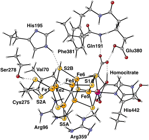 | ||
| Fig. 1 The model used for the present study, showing which amino acids were included. The model is built on the X-ray structure 3U7QS,2b and is here shown at the start of E4 with two hydrides. The numbering follows the one of the X-ray. | ||
The cofactor is reduced using a complicated mechanism which involves another protein, the Fe-protein, and with a consumption of two ATP for every electron. It has also long been known that one hydrogen molecule is produced for every nitrogen molecule reduced in the catalytic cycle. The overall reaction is,
| N2 + 8(H+,e−) + 16ATP → 2NH3 + H2 + 16ADP |
In V- and Fe- nitrogenase, significantly more H2 is produced, indicating a lower efficiency. It has also long been known that nitrogen is activated after four reductions in the catalytic cycle in the state E4.3 More recently, the most important experimental result obtained concerning the mechanism for nitrogen activation was made by EPR.4 It was shown that a formation of H2 from two hydrides is obligatory for nitrogen activation in E4. H2 formation and N2 activation were found to occur concertedly. These findings explain why H2 is always produced.
Two other experimental results will be mentioned here. Several studies have indicated that a sulfide might be lost from the cofactor somewhere along the catalytic cycle.5–7 However, if that is part of the actual catalysis has not been demonstrated. Another important, very recent, finding is that the carbide remains unprotonated in E4. That result is important because it has been found in theoretical studies that carbide protonation is thermodynamically favorable. These latter experimental results will be incorporated into the suggested mechanism, described below.
The present study is concerned with what happens in E4. The earlier steps have been investigated previously and assumed to be the same here,8 except for one difference in the E3 to E4 transition. The methodology used is the same as in our previous studies of nitrogenase.8–11 It has been demonstrated to yield a high accuracy, indicating error bounds of usually less than 3 kcal mol−1, for all redox enzymes studied so far.11
II. Methods
The methods used here are the same as in our earlier studies.8–11 Standard B3LYP was used for the geometry optimizations,12 with a medium size basis set (lacvp*). For the final energies, the basis set was substantially extended (cc-pvtz(-f)). The D2 dispersion effects were added,13 and solvation effects were computed with a dielectric constant of 4.0. Some comments are added for the differences to using a large constant of 30.0. The Gaussian14 and Jaguar15 programs were used for the calculations.Cluster modeling was used for the description of the active site.16 When a limited cluster is used, it is important that the main short-range electrostatic effects are included in the model. Long-range electrostatic effects mainly enter when the active site changes charge. It is therefore important that the cluster has the same charge during the entire course of the reaction, and that is the case here. In each reduction both a proton and electron are added to the cluster. Therefore, the charge remains the same. The cluster modeling with a similar size of model clusters have proven very accurate for a large number of systems studied.9
The same model was used as in our most recent study,8 with one exception. During the course of the present study, it was found that Cys275 became more important than previously expected, and was now modeled by its entire sidechain and three fixed atoms in the backbone. Since Ser278 is hydrogen-bonding to Cys275, it was also included. The following amino acids outside the cofactor were therefore included, His195, Arg96, Arg359, Glu380, Phe381, Gln191, Val70, and Ser278. The model is shown in Fig. 1. The fixed atoms are almost all back-bone alfa-atoms, fixed together with two of its hydrogen atoms. The exceptions are the two arginines, which have been cut a bit down from the backbone. In that case two atoms at the cutting position were fixed. Coordinates for the full model, including which atoms were fixed (marked with a #), are given in the ESI.† The charge of the model is −2, and the spin-states for the structures discussed here are all doublets. The protonation states for the amino acids are taken from earlier theoretical studies. Experimental pKa values for E4 do not exist. The main effect of entropy in the present type of reactions can, by experience, be taken from the loss/gain of translational entropy for the substrate reactant/product. Other entropy effects are small and ignored.
A comment on the redox potential for the reductant can finally be given. A value of −1.6 V was used in our earlier studies, which can be seen as a lower bound. A driving force for the electron transfer of 0.1 V was also used, giving an effective redox potential of −1.5 V. An exergonic driving force is actually not needed, since electron transfer could occur even if it is thermoneutral or even endergonic. On the other hand, the driving force for each entire reduction step needs to be exergonic. That said, the redox potential is not used in the present study, which concerns just the E4 state.
III. Results
a. Formation of E4
The present study starts from the computational results obtained previously for the steps preceding E4.8 The most important finding was that before the start of catalysis there should be four reduction steps. That result has been difficult to prove or disprove by experiments. The best way would be to compare results obtained after the first reductions of the ground state, with results for the E-states in catalysis. That approach has just started. In recent experimental studies of the E1 state obtained after one reduction of the ground state, it was found that one of the irons was reduced.17 In another study, an E1 state obtained by freeze quenching during catalysis for Fe-nitrogenase, instead found that one of the irons was oxidized indicated by the presence of a hydride.18 The two E1 states studied are apparently different. That should indicate that catalysis starts only after some initial reductions. Calculations were done to analyze the situation, and found very clearly that the E1 state obtained after one reduction of the ground state has a reduced iron.19 The E1 state during catalysis has previously been shown to have a hydride.8 Similar studies should be expected in the future. In the following, the four states obtained after reductions of the ground state will be termed A-states to avoid confusion.In the reduction steps, the cofactor needs to be protonated once for each reduction. With a mechanism where catalysis is preceded by four reduction steps, there is a need to find many positions for the protons. That is not energetically possible by just protonating the bridging sulfides of the cofactor. It was found in our initial studies that it is thermodynamically quite favorable to protonate the central carbide.20,21 However, protonating the carbide to methyl has a serious problem by leading to a too easy formation of methane, which would stop catalysis. An important result in this context was obtained in our previous study in which a sulfide was found to be lost from the cofactor in A4.8 Since the sulfide is protonated twice forming H2S, that takes away the necessity to protonate the carbide all the way to methyl. It should be emphasized that releasing H2S, is not thermodynamically lower in energy than protonating the carbide, but it is kinetically favored. Furthermore, it is important to note that the sulfide is lost before catalysis starts and, therefore, it does not need to be inserted again during catalysis. The general overall reaction given in the introduction is, therefore, still valid. When ATP or N2 ceases, the cluster becomes strongly oxidized and it will then be energetically favorable to insert the sulfur again.
A mechanism that releases a sulfide from the cofactor gives some support for the experiments that observed structures without a sulfide.5–7 However, the present way to release the sulfide is different from what was expected in the experimental analysis. There, it was generally assumed that the sulfide was replaced by N2. That has been shown to be energetically impossible.20 Which sulfide is lost is also different. Experimentally, S2B is lost, in the calculations S3A. The present sulfide loss mechanism can be termed sulfide release by reduction, allowed by the additional reduction steps before catalysis. However, the main importance of the extra reductions is to bring down most of the irons to its lowest possible stable redox state, namely Fe2+, which strongly increases the possibility to donate electrons to N2. Without the additional reductions, four Fe3+ would be present in the cofactor. With the release of the sulfide the carbide was found to be protonated only once in E4.8
Recently, after our latest study of the mechanism, it was shown experimentally that the carbide is not protonated at all in E4.22 With the results of our latest study, that was a partly surprising result. In the E3 to E4 transition it was found that protonation of the carbide was preferred thermodynamically by −8.5 kcal mol−1 compared to a sulfide protonation.8 It was also noted that protonating S4A, which was the energetically best alternative to carbide protonation, increased the number of protons that could lead to a destructive H2 formation by combining with a hydride. In the present study it was found that S2A is the preferred place for the additional proton in E4 rather than S4A. A protonation of the carbide cannot be avoided for thermodynamic reasons, so it has to be avoided kinetically. The barrier for protonation of the carbide was found to be quite high with 17.9 kcal mol−1.8 It is difficult to calculate a barrier for a protonation from the solvent to a sulfide, but combining the experimental result with the calculations indicate that the barrier for protonating S2A should be at most 15 kcal mol−1, which seems quite reasonable.
In summary of the previous studies, the thermodynamically preferred positions for the three protons are on the carbide. By a kinetic preference, one sulfide takes two of the protons and forms H2S and leaves the cofactor in A4. The third proton goes to S2A by, again, a kinetic preference compared to going to the carbide. All other protonations are obtained from energy optimizations. At the end, E4 has two hydrides and four protonated sulfides, S2B, S5A, S1A and S2A, see Fig. 2. An interesting result of the geometry optimization of the E4 state is that S2A swings out from Fe1 and Fe3 as it is protonated and becomes terminally bound to Fe2. The proton on S2A forms the weakest S–H+ bond of the four protonated sulfides, since it is the last sulfide to be protonated. It is therefore likely to be of interest for the subsequent protonation of N2. It should be recalled that the proton on S2A is only there because protonation of the carbide has a higher barrier. An important part of the nitrogenase mechanism in E4 concerns how to avoid a destructive formation of H2 from a hydride and a proton. The oxidation state of the cofactor is Mo3+ 7Fe2+ and the best spin-coupling has negative spin on Fe2, Fe3 and Fe4 here denoted as (−2,−3,−4), where the numbering follows the one in the X-ray structure. The redox state of E4 is obtained from the known redox state of the A0 ground state4,20 and from the 8 reductions needed to reach E4. The redox state for individual Fe atoms can in general not be seen on the populations since the electrons are very delocalized. However, it can sometimes be guessed from the spin-populations, as discussed in the text below. Population charges are of little use. For Mo, the spin population is useful in the decision on its redox state.
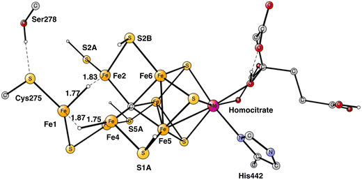 | ||
| Fig. 2 The structure of the cofactor at the start of E4. There are two hydrides and four protonated sulfides, S2B, S1A, S5A and S2A. | ||
b. The formation of H2 from two hydrides
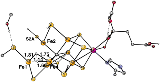
Following the analysis of the EPR study,4 the first step in E4 is to form H2 from the two hydrides. That leads to a further decrease of the formal oxidation state to Mo3+ 5Fe2+ 2Fe1+, an extremely low oxidation state for the cofactor which has weak field ligands. The unusual presence of two Fe(I) is similar to the unusual presence of an oxygen radical in PSII and the unusual presence of a methyl radical in MCR.9 It should also be noted that the structure with two Fe(I) is rather high in energy at +8.7 kcal mol−1, see below.The optimal positions of the two hydrides can be seen in Fig. 2. One of them is bridging between Fe1 and Fe2, the other one between Fe1 and Fe4. The hydride between Fe1 and Fe2 appeared in that position already in E2. The hydride between Fe1 and Fe4, was first bound between Fe4 and Fe5 in A4, but moved to a position between Fe1 and Fe2 in the E3 to E4 transition. When the latter hydride moved to that position, its original position between Fe4 and Fe5 was replaced by S1A. The details of this structural change have been described previously.8 It is interesting to note that an open area is created in between Fe1, Fe2 and Fe4 by the movement of S2A and S1A.
The TS for H–H bond formation from the two hydrides was relatively easy to locate. The TS structure is shown in Fig. 3. It is similar to what was obtained in the previous study but modified mainly because of the displacement of S2A, resulting from the additional protonation. The barrier is 17.7 kcal mol−1 compared to the previous value of 18.2 kcal mol−1. Like in the previous study, the hydrides are energetically difficult to move around on the cofactor and therefore have to be placed in the right area the first time they appear in the mechanism. The reaction energy for H2 release came as a rather big surprise. It is endergonic by +8.7 kcal mol−1, which includes a large gain of entropy of −8.4 kcal mol−1. The endergonicity can be compared to the one of +0.9 kcal mol−1 obtained in the previous study. The open area created by the loss of the hydrides is apparently not very stable. A large effort was spent, trying to find a more optimal structure but it was not successful. For example, moving S2A to a bridging position between Fe1 and Fe2 and moving its proton to Cys275, is endergonic by +1.0 kcal mol−1. However, another important effect of protonating Cys275 is that the spin on Fe1 drops to a very low value of −3.02, which means that Fe1 has a quite localized Fe1+ character. It can be added that the findings for the N2 activation, described below, makes the large endergonicity for H2 formation quite reasonable compared to experiments.
c. The binding of N2.
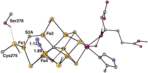
The best position to bind N2 was found to be end-on binding to Fe4, see Fig. 4, which is the same position as found in the previous study. One reason is that Fe4 is the least coordinated Fe atom, if the (weak) binding between the irons is included. That is manifested by the low spin-population of −3.17, indicating contribution of Fe1+ character. Only Fe1 has a similar spin population. As N2 binds there is a change of spin-coupling from (−2,−3,−4) to (−2,−4,−7) with an energy lowering of 2–3 kcal mol−1 for all structures from this point on. The exothermicity of the binding of N2 is quite large with −12.7 kcal mol−1, but subtracting the loss of translational entropy for N2 of +9.9 kcal mol−1 makes the free energy of binding N2 rather small with −2.8 kcal mol−1. With the large endergonicity for H2 formation of +8.7 kcal mol−1, this means that the process from the start of E4 is so far endergonic by +5.9 kcal mol−1. This means that the binding of N2 cannot be the end-point of E4, as was thought in our previous study. It means that N2 must be protonated already in E4. An important difference of the E4 state compared to the previous study is that the carbide is now unprotonated.Another argument for N2 protonation already in E4 is the following. If better energies for H2 release and N2 binding had been found and N2 reaches E5 unprotonated, the protonation of N2 would have to be made in E5. However, the present calculations on E5 show that the reduction step from E4 to E5 would then lead to a formation of another hydride, not a protonation of N2. That scenario is reasonable since two hydrides were lost in E4. Therefore, the reduction process in E5 would go backwards from E5 by formation of unproductive H2 from the hydride and a proton (an hp reaction). Also, if N2 was not protonated in E4, the cofactor would reach E5 with a very low oxidation state with two Fe1+, which would be very reactive and, therefore, dangerous for the enzyme.
The free energy of binding N2 on Fe4 is rather small as described above, but it does not mean that the effects on the structure and wavefunction are negligible. There are two important effects of the binding. One is the movement of the protonated S2A from its on-top position on Fe2, towards a bridging position between Fe1 and Fe2. Furthermore, after that, S2A loses its proton to Cys275, see Fig. 4. At the same time, the hydrogen bond between Ser275 and Cys275 weakens considerably. These changes of the structure lower the energy by as much as −12.4 kcal mol−1, and are the beginning of what occurs in the next steps, see below. The structural changes are related to the presence of local Fe1+ character. Finally, it was tested whether the same structural changes would be favorable also before N2 binds, but they were not. The structures with an without the structural change then have very similar energies. The structure with a protonated S2A on-top of Fe2 is actually favored by 1.0 kcal mol−1. Therefore, it is mainly the binding of N2 that causes the structural changes.
Many alternative positions were investigated in the previous study and some of them also here. Experimentally, Fe6 is suggested to be the favored position.4 The reason is that a mutation of Val70 with Ile has major effects on nitrogenase activity. The closest positions to Val70 on the cofactor are Fe2 and Fe6. If the main effect of Val70 was on N2 binding, it is a natural conclusion that Fe6 is the position for N2 binding. However, in the present study, Fe4 is the energetically favored position by as much as 12.4 kcal/compared to Fe6. Therefore, another explanation for the effect of the Val70Ile mutation has to be found, and this will be discussed below. With the experience of the accuracy of the present methodology, an error in the calculation should be ruled out.
The computed big difference in energy between the N2 positions on Fe4 and Fe6 comes almost entirely from the structural changes, described above, which are big for the binding on Fe4 but have no correspondence for Fe6. Attempts to move the proton on S2A over to Cys275 in the case of Fe6-N2 led to much higher energies. These differences between the binding of N2 on Fe4 and Fe6, are due to the localized character of Fe1+ in the Fe1, Fe2, Fe4 region. Apart from the structural changes, they have very similar structures. For Fe4–N2, the Fe–N distance is 1.89 Å and the N–N distance 1.13 Å, for Fe6–N2 they are 1.88 Å and N–N 1.13 Å. The total charge transfer to N2 is the same with −0.29 both for Fe4–N2 and Fe6–N2. However, they are slightly different for the two nitrogen atoms. For Fe4–N2, the outer nitrogen has more charge and spin, −0.18 and 0.20, respectively, compared to −0.11 and 0.03 for the nitrogen closest to Fe4. For Fe6–N2, they are −0.11 and −0.04 for the outer nitrogen and −0.18 and −0.19 for the inner one. These rather small differences come both from the difference in spin and charge distribution of the cofactor and differences in steric effects from nearby groups. For Fe6–N2, there is a short distance between a hydrogen on Gln191 and the outer nitrogen of 2.65 Å, while all corresponding distances are very long for Fe4-N2. On the other hand, there is a rather strong hydrogen bond between N2 and His195 with a distance of 2.10 Å for Fe6–N2. However, these differences appear to have only small effects on the relative binding of N2 on Fe4 and Fe6.
d. The protonation of N2
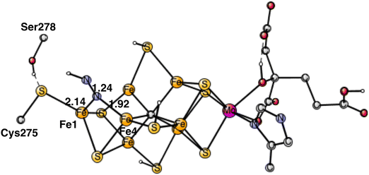
The rather open area in between Fe1, Fe2 and Fe4, continues to be the most important part of the cofactor as N2 becomes protonated. In the lowest energy N2H product, shown in Fig. 5, the unprotonated nitrogen forms a strong bond to Fe4. The bond to Fe4 is slightly elongated from1.89 Å for N2 to 1.92 Å for N2H. Apart from the bond to Fe4 which remains almost intact, there is also a bond to Fe1. The distance between Fe1 and N2H is longer with 2.14 Å. The protonation of N2 requires 4.0 kcal mol−1. Since the N2 structure is 5.9 kcal mol−1 higher than the starting point for E4, the energy for N2H is at +9.9 kcal mol−1 from the start.The structure in Fig. 5 is by far the best structure found for N2H. In particular, taking the proton from Cys275, is much better than taking it from the sulfides. Keeping the same structure as the one in the figure for N2H but having S2B or S1A as proton donors rather than Cys275, leads to about 15 kcal mol−1 higher energies. Changing the N2H structure in different ways in the latter cases, keeping it in the same region, led to only minor improvements. A structure for N2H in the region between Fe2 and Fe6 was also optimized. N2H was found to bind to both Fe2 and Fe6 with its unprotonated nitrogen, and with one bond to Fe6 with its protonated nitrogen. That structure is +15.1 kcal mol−1 higher than the one in Fig. 5. The difference is actually a little bit larger than for the case of N2. Steric hindrance might play a minor role for that difference.
The present analysis of the results described above is the following. A key factor in the activation of N2 is the presence of two Fe1+ atoms, which appear after the loss of the two hydrides from the Fe1, Fe2, Fe4 region. An important question is where the two loosely bound Fe1+ electrons are localized. The calculations show clearly that those electrons remain in the Fe1, Fe2, Fe4 region. An indication of the presence of the electrons in this area is that S2A moved in towards Fe1 in the geometry optimization when N2 became bound. The first one of the Fe1+ electrons moved to Fe1, where the protonated Cys275 is bound, and is used in a hydrogen atom transfer to N2, see below. The second one stays in the Fe1, Fe2, Fe4 area. Therefore, it is important that the N2 protonation occurs in that region.
It is interesting to note that, of the two ends of the cofactor, Fe1 is quite involved in the chemistry, including its Cys275 ligand, while molybdenum, in the other end, is much less involved, an almost opposite situation to the one that was expected for decades, where molybdenum was thought of as a key factor for N2 binding. Still, it is clear that molybdenum and its homocitrate ligand are essential for the cofactor.
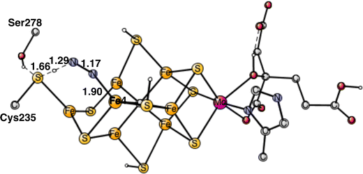
To start the proton transfer from Cys235, N2 on Fe4 bends towards the proton, but keeps its bond to Fe4. The transition state for proton transfer was one of the most difficult parts to characterize in the present study and the best alternative found is still not entirely satisfactory. Not only the motion of the proton is involved in the TS, but also the transfer of two electrons to N2. It is not a simple hydride transfer because one of the electrons does not come from Fe1 but from the rest of the cofactor. Since there was not much electron transfer to N2 when it was bound to Fe4, the oxidation state of the cofactor still has almost two Fe1+, which means that two electrons are rather weakly bound to the cofactor. The electron transfer occurs for a structure, where the distance between Cys275 and N2 is short and the transfer is sudden. The search for a TS from the reactant with a long distance between them did not lead to any progress. Starting with the proton close to Cys275 and moving it towards N2 just led to higher and higher energies as the distance to N2 got closer. The behavior was the same, starting from the other end. Many other attempts were tried. Finally, moving N2 closer and closer to the sulfur of Cys275 an optimized TS was reached. Also, SCF convergence to the right state was difficult with several low-lying states. The optimized TS is shown in Fig. 6. As seen in the figure, both the S-H and H-N distances are short with 1.66 Å and 1.29 Å, respectively. The barrier for the transfer was calculated to be 17.6 kcal mol−1. Since the starting point is +5.9 kcal mol−1, see above, a total barrier of +23.5 kcal mol−1 is reached at the TS. Since the highest barrier should be 18–19 kcal mol−1 and the usual overestimation of barriers is 2–3 kcal mol−1,9 the calculated barrier is somewhat too high. Very many other attempts were made to improve the description of the process but without success. For example, using the spin-coupling (−2,−3,−4) increased the barrier by 1.9 kcal mol−1. There are a few other possibilities. The first one is that the method error is larger than usual. Considering the character of the TS with a transfer of two electrons and one proton, that is perhaps the best possibility. Since the two electrons are taken from the cofactor, there are quite large geometric effects, which stretches all the way to molybdenum. A surprising effect is a very large dispersion effect, raising the total barrier from +17.5 to +23.5 kcal mol−1. Using the DFT-D3 approximation23 reduces the dispersion effect, but only by 1.0 kcal mol−1. The possibility that there could be a dispersion effect from outside the present model was investigated by including also the nearest amino acids, but it did not make any difference.
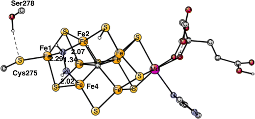
The end-point for E4 is N2H2, shown in Fig. 7. One nitrogen has a single bond to Fe4 with a distance of 2.02 Å, while the other nitrogen has two bonds, to Fe1 and Fe2, with distances 2.29 Å and 2.07 Å, respectively. As a comparison, the binding of N2H2 to Fe2 and Fe6, as suggested by many experiments, has an energy, which is +15.9 kcal mol−1 higher. The reason is that the Fe1+ character is much larger in the Fe1, Fe2, Fe4 region, from where the two hydrides have been released. The Fe2, Fe6 region is so electron deficient that N2H2 has strong radical character. If N2H2 is moved after its formation in the Fe1, Fe2, Fe4 region to the Fe2, Fe6 region, the energy would go up by +15.9 kcal mol−1. Since the regular full E4 mechanism is exergonic by only −5.9 kcal mol−1, see below, an end point with N2H2 between Fe2 and Fe6, would be strongly endergonic. The reason the N2H2 structure has been observed between Fe2 and Fe6,7 could be that it was bound without a preceding loss of two hydrides. A structure has been optimized for which two protons have been added on the sulfides and N2H2 placed between Fe2 and Fe6. N2H2 is then strongly bound by about 25 kcal mol−1. The structure is shown in Fig. S1 (ESI†).
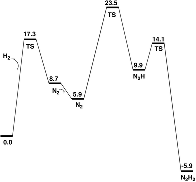
The formation of N2H2, shown in Fig. 7, from N2H is very exergonic by −15.8 kcal mol−1. Overall, the exergonicity of the entire E4 step is −5.9 kcal mol−1. That makes the E4 step rather easily reversible, in very good agreement with experiments, which can make the reaction go back to the starting point of E4 by changing the pressure of N2. The energy diagram for the E4 steps is shown in Fig. 7. It should be noted that the barrier given for the H2 formation is +17.3 kcal mol−1, see further below. It can be seen in the diagram that the release of H2 from the two hydrides is endergonic by +8.7 kcal mol−1, which means that there are no observable intermediates until the entire E4 step is finished. Without N2, the reaction will just go back to the starting point for E4, which is again in very good agreement with experimental observations.
For the TS for protonating the other end of N2, the proton needs to be taken from a protonated sulfide. Since N2H is bound to Fe4, the proton on S1A is best positioned. Still, the distance between the nitrogen of N2H and the proton on S1A is quite long, with 4.04 Å, and the cofactor is rather rigid and cannot easily deform to make the distance shorter. To bridge that distance, water molecules are involved. It was shown in a recent study, that it is a possible mechanism for nitrogenase.24 With one water bridging S1A and N2H, the barrier is 7.3 kcal mol−1. With two water molecules, the optimized TS is shown in Fig. 8. As usual, for this type of transition states there is a formation of H3O+ or a H5O2+.24 For one of the water molecules, the O–H distances at the TS are 1.11 Å, 1.19 Å and 0.97 Å. It has a barrier of 4.2 kcal mol−1, 3.1 kcal mol−1 lower than with one water. The free energy cost of +2.0 kcal mol−1 for bringing the water molecule(s) from bulk water to the TS region is included in the barrier. Since N2H is +9.9 kcal mol−1 higher than the starting point for E4, the TS is at 14.1 kcal mol−1, which makes the computed barrier fall below the maximum allowed of 18–19 kcal mol−1.
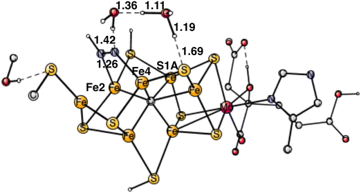 | ||
| Fig. 8 Optimized transition state for proton transfer between S1A and N2H using two water molecules. | ||
For the energies in Fig. 9, a dielectric constant of 4.0 was used for the solvation energies. Since the cofactor is charged and surrounded by water a larger constant of 30.0 was also tried. The differences to using 4.0 are generally rather small for the relative energies, for equilibria 0–2 kcal mol−1 and somewhat larger for the TS structures with 0–3 kcal mol−1. The differences do not change the mechanism. The reason the differences are small is that a rather large model of 180 atoms is used.16
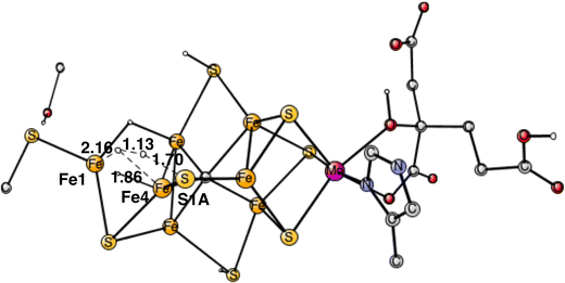
The next forbidden reaction is the one between a proton on S1A and a hydride. The optimized TS is shown in Fig. 11. The calculated barrier is +22.3 kcal mol−1, which is larger than the allowed formation of H2 from two hydrides. It is sufficiently large for avoiding that forbidden pathway.
The final forbidden reaction is the one between a proton on S2A and a hydride. The optimized TS is shown in Fig. 12. The calculated barrier turned out to be quite small with only 14.1 kcal mol−1, which is significantly lower than the allowed reaction between two hydrides of 17.7 kcal mol−1. This forbidden side-reaction would therefore cause a major problem for the mechanism of protonating N2. A problem is that the S2A can form strong bonds to both Fe2 and Fe3 at the TS. We shall again address to this reaction below.
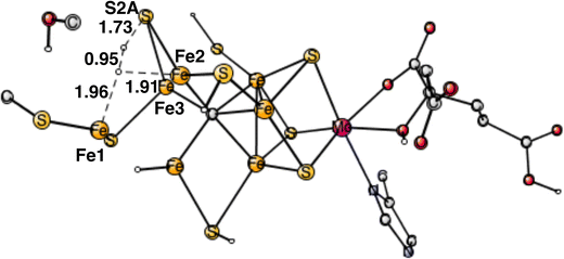 | ||
| Fig. 12 Optimized TS for the reaction between a proton on S2A and a hydride. S2A is bound to both Fe2 and Fe3. | ||
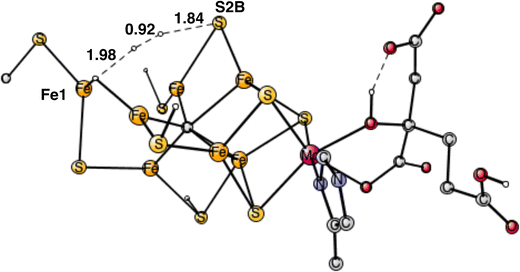
In summary, of the three forbidden reactions, the one with a proton on S1A does not cause any problem, the one with a proton on S2B would lead to a loss of nitrogenase activity. The one with a proton on S2A would cause major problems. For all other possible forbidden hp reactions, the distance between the proton and the nearest hydride is sufficiently large not to cause any problems. To bridge the distances by including water molecules in the TS, like in Fig. 8, does not lead to lower barriers in this case, since protonated waters are not formed at the TS.
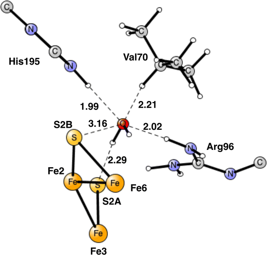
For the reasons given, the area around Val70 was studied further. It is a rather open area and the binding of a water molecule close to Val70 appears possible. After some investigations a position for a bound water was found as shown in Fig. 13. The water has hydrogen bonds to S2A to His195 and to Arg96. The water is also within van der Waals distance to Val70. Neglecting entropy, the calculated binding energy is +17.4 kcal mol−1, which is larger than +14 kcal mol−1 for a water molecule in water. The water molecule in the Val70 region should therefore be bound by about 3 kcal mol−1. However, since the water is not bound to any metal, it can move rather freely in this region, which means that not all translational entropy should be lost. A free energy binding of the water of 6 kcal mol−1 appears reasonable.
The most interesting of the hydrogen bonds is the one to S2A. It is rather short with 2.29 Å. Therefore, it is possible that it will affect the hp reaction between the proton on S2A and the nearest hydride. Without the water the barrier was found to be only 14.1 kcal mol−1, which is significantly lower than the one for the allowed reaction between the two hydrides of 17.7 kcal mol−1. One reason the barrier was so low was that S2A can form two bonds to Fe2 and Fe3. With the water molecule present, the optimized TS is shown in Fig. 14. It can be seen that S2A does no longer form a bond to Fe1 and the barrier is significantly increased from 14.1 to 21.3 kcal mol−1, showing that this non-allowed side-reaction will no longer cause any problems. The conclusion drawn here is that it is the presence of a water close to Val70 that has led to the observations of significant loss of activity for the Val70Ile mutation.
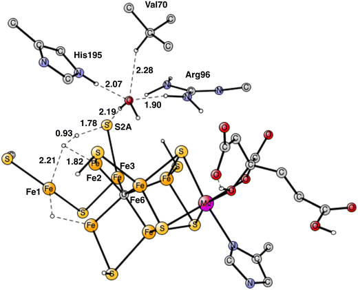 | ||
| Fig. 14 Optimized TS for the reaction between a proton on S2A and a hydride after addition of one water molecule. S2A is bound only to Fe3. | ||
The other somewhat problematic side-reaction between the proton on S2B and a hydride was also reinvestigated. The optimized TS gave a barrier of 20.0 kcal mol−1 compared to 18.1 kcal mol−1 without the water. The effect of the water molecule for the allowed reaction is small, as expected, decreasing the barrier from 17.7 kcal mol−1 to 17.3 kcal mol−1.
IV. Summary
The most important step in the nitrogenase mechanism concerns the first protonations of N2 in E4. A calculated energy diagram is shown Fig. 9. The first step in E4 is the formation of H2 from two hydrides (an hh reaction). The two hydrides were found to be bound in the Fe1, Fe2, Fe4 region. The computed barrier for the hh reaction is 17.3 kcal mol−1, which is lower than the overall rate-limiting barrier of 18–19 kcal mol−1. In this context, it should be noted that barriers using the present methodology are in general overestimated by 2–3 kcal mol−1. The allowed hh reaction competes with the non-allowed reactions between a hydride and a proton (an hp) reaction, which if it occurs would just lead back to the E2 state. If any hp reaction is faster than the allowed hh reaction, nitrogenase activity would cease.Three hp reactions with potential problems have been identified. In the first one of them (S1A-H), the barrier is significantly higher than the hh reaction, see Fig. 11. In the second one (S2B-H) the barrier is only slightly higher than 17.3 kcal mol−1, see Fig. 10. However, in the third one involving S2A-H, the calculated barrier is only 14.1 kcal mol−1, see Fig. 12. By including a water molecule in the Fe2–Fe6 region with a hydrogen bond to S2A, see Fig. 14, the barrier increased to 21.3 kcal mol−1. It also increases the barrier for S2B-H to 20.0 kcal mol−1. The inclusion of a water molecule within van der Waals distance to Val70 also explains the experimental observations of a significant decrease of activity for the Val70Ile mutant.
The open region in between Fe1, Fe2, Fe4 where the two excess electrons remain after the release of the two hydrides, is the main area for the activation of N2. The lowest energy structure for a bound N2 is found to be with N2 on top of Fe4. Even if the free energy of binding is only −2.8 kcal mol−1, there are significant structural effects involving Cys275 and S2A. The by far lowest energy for N2H is found for a structure bound between Fe1 and Fe4, see Fig. 5. N2H2 is bound in the same region, see Fig. 7. The entire E4 step is exergonic by only −5.9 kcal mol−1, which explains the observed reversibility.
A low energy TS for the first protonation of N2 was hard to locate. The TS, shown in Fig. 6, has a local barrier of 17.6 kcal mol−1 and a total barrier of 23.5 kcal mol−1, which is slightly too high. A likely explanation for the too high barrier is a minor problem with the methods for this complicated reaction step involving one proton and two electrons. For the second protonation step of N2, the inclusion of two water molecules gave a low local barrier of 4.2 kcal mol−1 leading to a total barrier of 14.1 kcal mol−1.
The present mechanism agrees with all available experiments. It agrees with the Thorneley-Lowe kinetic experiments which showed that activation of N2 occurs after four reductions in the catalytic cycle, in E4.3 It agrees with the EPR experiments which showed that H2 release from two hydrides is obligatory for N2 activation and that the E4 step is reversible.4 It agrees with the finding that the carbide is unprotonated in E4.22 It agrees with the finding that mutation of Val70 significantly disturbs the nitrogenase activity.4 It agrees with the fact that all non-allowed hp reactions have higher barriers than the allowed hh reaction. It also agrees with the most recent experiments for E1, that there is no hydride for a single reduction of the ground state, but that E1 in the catalytic cycle has a hydride.
Conflicts of interest
There are no conflicts to declareAcknowledgements
The computations were enabled by resources provided by the National Academic Infrastructure for Supercomputing in Sweden (NAISS) and the Swedish National Infrastructure for Computing (SNIC) at National Supercomputer Centre (NSC) partially funded by the Swedish Research Council through grant agreements no. 2022-22-955 and no. 2018-05973.References
- J. Kim and D. C. Rees, Structural models for the metal centers in the nitrogenase molybdenum-iron protein, Science, 1992, 257, 1677–1682 CrossRef CAS PubMed.
- (a) K. M. Lancaster, M. Roemelt, P. Ettenhuber, Y. Hu, M. W. Ribbe, F. Neese, U. Bergmann and S. De Beer, Science, 2011, 334, 974–976 CrossRef CAS PubMed; (b) T. Spatzal, M. Aksoyoglu, L. M. Zhang, S. L. A. Andrade, E. Schleicher, S. Weber, D. C. Rees and O. Einsle, Science, 2011, 334, 940 CrossRef CAS PubMed.
- R. N. F. Thorneley and D. J. Lowe, in Kinetics and mechanism of the nitrogenase enzyme system, Molybdenum enzymes, ed. T. Spiro, Wiley, New York, NY, 1985, pp. 221–284 Search PubMed.
- B. M. Hoffman, D. Lukoyanov, Z.-Y. Yang, D. R. Dean and L. C. Seefeldt, Mechanism of Nitrogen Fixation by Nitrogenase: The Next Stage, Chem. Rev., 2014, 114, 4041–4062 CrossRef CAS PubMed.
- T. Spatzal, A. Kathryn, K. A. Perez, O. Einsle, J. B. Howard and D. C. Rees, Ligand binding to the FeMo-cofactor: Structures of CO-bound and reactivated nitrogenase, Science, 2014, 345, 1620–1623 CrossRef CAS PubMed.
- T. M. Buscagan and D. C. Rees, Rethinking the Nitrogenase Mechanism: Activating the Active Site, Joule, 2019, 3, 2662–2678 CrossRef CAS PubMed.
- W. Kang, C. C. Lee, A. J. Jasniewski, M. W. Ribbe and Y. Hu, Structural evidence for a dynamic metallocofactor during N2 reduction by Mo-nitrogenase, Science, 2020, 368, 1381–1385 CrossRef CAS PubMed.
- W.-J. Wei and P. E. M. Siegbahn, A Mechanism for Nitrogenase Including a Loss of a Sulfide, Chem. Eur. J., 2022, e202103745 CAS.
- M. R. A. Blomberg, T. Borowski, F. Himo, R.-Z. Liao and P. E. M. Siegbahn, Quantum Chemical Studies of Mechanisms for Metalloenzymes, Chem. Rev., 2014, 114, 3601–3658 CrossRef CAS PubMed.
- P. E. M. Siegbahn and M. R. A. Blomberg, A Systematic DFT Approach for Studying Mechanisms of Redox Active Enzymes, Front. Chem., 2018, 6, 644 CrossRef CAS PubMed.
- P. E. M. Siegbahn, A quantum chemical approach for the mechanisms of redox-active metalloenzymes, RSC Adv., 2021, 11, 3495–3508 RSC.
- A. D. Becke, Density-functional thermochemistry. III. The role of exact exchange, J. Chem. Phys., 1993, 98, 5648–5652 CrossRef CAS.
- S. Grimme, Semiempirical GGA-type density functional constructed with a long-range dispersion correction, J. Comp. Chem., 2006, 27, 1787–1799 CrossRef CAS PubMed.
- M. J. Frisch, G. W. Trucks, H. B. Schlegel, G. E. Scuseria, M. A. Robb, J. R. Cheeseman, G. Scalmani, V. Barone, B. Mennucci, G. A. Peterssonet al., Gaussian 09, Revision A.1, Gaussian, Inc., Wallingford CT, 2009 Search PubMed.
- Jaguar, version 8.9, Schrodinger, Inc., New York, NY, Bochevarov, A.D., 2015 CrossRef; E. Harder, T. F. Hughes, J. R. Greenwood, D. A. Braden, D. M. Philipp, D. Rinaldo, M. D. Halls, J. Zhang and R. A. Friesner, Jaguar: A high-performance quantum chemistry software program with strengths in life and materials sciences, Int. J. Quantum Chem., 2013, 113, 2110–2142 CrossRef.
- P. E. M. Siegbahn and F. Himo, The Quantum Chemical Cluster Approach for Modeling Enzyme Reactions, Wiley Interdiscip. Rev.: Comput. Mol. Sci., 2011, 1, 323–336 CAS.
- C. Van Stappen, R. Davydov, Z.-Y. Yang, R. Fan, Y. Guo, E. Bill, L. C. Seefeldt, B. J. Hoffman and S. DeBeer, Spectroscopic Description of the E1 State of Mo Nitrogenase Based on Mo and Fe X-ray Absorption and Mössbauer Studies, Inorg. Chem., 2019, 58, 12365–12376 CrossRef CAS PubMed.
- D. A. Lukoyanov, D. F. Harris, Z.-Y. Yang, A. Pérez-González, D. R. Dean, L. C. Seefeldt and B. M. Hoffman, The One-Electron Reduced Active-Site FeFe-Cofactor of Fe-Nitrogenase Contains a Hydride Bound to a Formally Oxidized Metal-Ion Core, Inorg. Chem., 2022, 61, 5459–5464 CrossRef CAS PubMed.
- P. E. M. Siegbahn, Can the E1 state in nitrogenase tell if there is an activation process prior to catalysis?, Phys. Chem. Chem. Phys., 2023, 25, 3702–3706 RSC.
- P. E. M. Siegbahn, Model Calculations Suggest that the Central Carbon in the FeMo-cofactor of Nitrogenase Becomes Protonated in the Process of Nitrogen Fixation, J. Am. Chem. Soc., 2016, 138, 10485–10495 CrossRef CAS PubMed.
- P. E. M. Siegbahn, The mechanism for nitrogenase including all steps, Phys. Chem. Chem. Phys., 2019, 21, 15747–15759 RSC.
- D. A. Lukoyanov, Z.-Y. Yang, A. Pérez-González, S. Raugei, D. R. Dean, L. C. Seefeldt and B. M. Hoffman, 13C ENDOR Characterization of the Central Carbon within the Nitrogenase Catalytic Cofactor Indicates That the CFe6 Core Is a Stabilizing “Heart of Steel”, J. Am. Chem. Soc., 2022, 144, 18315–18328 CrossRef CAS PubMed.
- L. Goerigk, A. Hansen, C. Bauer, S. Ehrlich, A. Najibi and S. Grimme, A look at the density functional theory zoo with the advanced GMTKN55 database for general main group thermochemistry, kinetics and noncovalent interactions, Phys. Chem. Chem. Phys., 2017, 19, 32184–32215 RSC.
- P. E. M. Siegbahn, How protons move in enzymes – the case of nitrogenase, J. Phys. Chem. B, 2023, 127, 2156–2159 CrossRef CAS PubMed.
- D. A. Lukoyanov, Z.-Y. Yang, K. Shisler, J. W. Peters, S. Raugei, D. R. Dean, L. C. Seefeldt and B. M. Hoffman, A conformational equilibrium in the nitrogenase MoFe protein with an a-V70I amino acid substitution illuminates the mechanism of H2 formation, Faraday Discuss., 2023, 243, 231–252 RSC.
- Y. Pang and R. Björnsson, Understanding the Electronic Structure Basis for N2 Binding to FeMoco: A Systematic Quantum Mechanics/Molecular Mechanics Investigation, Inorg. Chem., 2023, 62, 5357–5375 CrossRef CAS PubMed.
- L. Cao and U. Ryde, Putative reaction mechanism of nitrogenase after dissociation of a sulfide ligand, J. Catal., 2020, 391, 247–259 CrossRef CAS.
Footnote |
| † Electronic supplementary information (ESI) available: Coordinates for all structures discussed in the text. See DOI: https://doi.org/10.1039/d3cp02851h |
| This journal is © the Owner Societies 2023 |

