Insights into an air-stable methylene blue catholyte towards kW-scale practical aqueous organic flow batteries†
Yonghui
Zhang
ab,
Fan
Li
cd,
Tianyu
Li
 a,
Mengqi
Zhang
ad,
Zhizhang
Yuan
 a,
Guangjin
Hou
 c,
Jie
Fu
*b,
Changkun
Zhang
*a and
Xianfeng
Li
 *a
*a
aDivision of Energy Storage, Dalian National Laboratory for Clean Energy (DNL), Dalian Institute of Chemical Physics, Chinese Academy of Sciences, 457 Zhongshan Road, Dalian 116023, P. R. China. E-mail: zhangchk17@dicp.ac.cn; lixianfeng@dicp.ac.cn
bCollege of Environmental and Chemical Engineering, Dalian Jiaotong University, 794 Huanghe Road, Dalian, 116028, P. R. China. E-mail: fj@djtu.edu.cn
cState Key Laboratory of Catalysis, Dalian National Laboratory for Clean Energy (DNL), Dalian Institute of Chemical Physics, Chinese Academy of Sciences, 457 Zhongshan Road, Dalian 116023, P. R. China
dUniversity of Chinese Academy of Sciences, Beijing 100049, P. R. China
First published on 1st December 2022
Abstract
Aqueous organic flow batteries (AOFBs) possess unique advantages, including element abundance and tailorability, compared to the traditional flow batteries (FBs). However, achieving an air-stable and high-performance electrolyte is still one of the main challenges for their practical applications. Generally, the stability of an aqueous organic electrolyte is associated with the structure of the organic redox-species and electrolyte environment. By the virtue of electrolyte optimization and in situ/ex situ NMR and EPR techniques, we found in the methylene blue (MB) electrolyte that both oxygen-resistant MB radicals generated by the comproportionation reaction and reduced MB states in the acidic electrolyte displayed much more stable molecular structures. This definitely plays a vital role in the high reversibility of MB molecules under ambient air conditions. Taking advantage of the air-stable MB electrolyte, a kW-scale AOFB stack was assembled for the first time, which exhibited stable capacity at 80 mA cm−2 for over 500 cycles. Moreover, the stack based on 0.5 M MB electrolyte still achieved a stable long-life cycle performance for ∼32 days with a capacity of ∼510 A h. The impressive stack performance enables the MB catholyte to be a promising candidate for large-scale energy storage.
Broader contextFlow batteries (FBs) are one of the best options for large-scale and long-duration energy storage in the development of clean renewable energy. Aqueous organic flow batteries (AOFBs), which utilize organic molecules as the redox species, exhibit unique advantages such as elements abundance and customizability, thereby enabling the potential environmental friendliness and low cost. However, current AOFBs still are restricted by the lack of an air-stable organic molecule. Herein, we found that both oxygen stable intermediate radicals and reduced states contribute to the high reversibility of MB molecules under ambient air condition by the in situ/ex situ NMR and EPR techniques. Furthermore, a kW-scale AOFB stack was assembled for the first time and exhibited stable long-life cycle performance for ∼32 days with the capacity of ∼510 Ah. This work shows not only a significant finding in the air-stable molecules but also an inspiring successful scale-up attempt, which could be a milestone for the development of AOFBs towards practical application. |
Introduction
The electrical grid requires high safety, long duration and low levelized cost energy storage technologies to accept more wind and solar intermittent renewable energy sources with increasing demand for a carbon-neutral society.2–5 Flow batteries (FBs), possessing fast response, long cycling life, and mutually independent power and energy design can be scaled up feasibly as long-duration energy storage.6–9 Numerous different FB technologies, especially for vanadium FBs (VFBs), have been successfully demonstrated around the world over the past 50 years.7,10 The main hindrances of the current development of FBs are low energy density and relatively high cost.11Compared to conventional FBs with inorganic metal ions as redox-active species (RASs), aqueous organic FBs (AOFBs) utilize organic molecules as RASs and are expected to enhance energy density and lower electrolyte costs owing to the excellent structural tunability, earth abundance and low cost of organic molecules.12–17 Thus far, many types of organic RASs have been investigated in AOFBs, including quinones,18–21 TEMPOs (2,2,6,6-tetramethyl-1-piperidinyloxy),22,23 ferrocene,24 viologens,25–27 aromatic heterocycles,28–30 fluorenone,31 and polypeptides,32 and quite impressive progress has been achieved in recent years. Among them, aromatic heterocycles, such as alloxazine,33 phenazine,28,29,34 and phenothiazine,30,35 display more reversible electrochemical performance. Moreover, the solubility of aromatic heterocycles is very poor in aqueous solution due to their symmetric molecular skeleton, and the hydrophilic group functionalization and electrolyte optimization have already been utilized to promote their solubility.36 Many reported organic RASs in the intermediate and reduced states are sensitive to oxygen. This restricts cell evaluation under an inert atmosphere and would be a great challenge in real applications.24,27,37 Therefore, the design of air-stable organic RASs is one of the critically important tasks for the wide application of AOFBs.38–40 One phenothiazine derivative, methylene blue (MB) molecule, has been recently reported to achieve high solubility and excellent stability in acetic acid (AA)–water solutions.30 However, the underlying mechanism of the reversible redox reaction in the MB electrolyte is yet unclear.
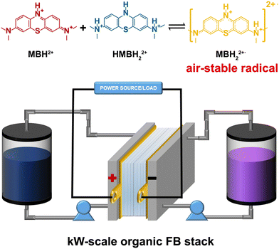
Herein, by virtue of in situ and ex situ nuclear magnetic resonance (NMR) and electron paramagnetic resonance (EPR) measurements on the redox reaction mechanism of the MB electrolyte, the oxygen resistance of its intermediate radicals and reduced MB was detected. This accounts for the high stability of the MB electrolyte in the air condition, as the comproportionation reaction of the MB molecules always occurred during cycling. Most importantly, a kW-scale AOFB stack was firstly assembled based on the air-stable MB electrolyte (Scheme 1), indicating that the MB electrolyte can be a promising air-stable organic electrolyte for large-scale energy storage.
Results and discussion
The electrolyte composition was optimized by tuning the ratio of AA and H2SO4 in the aqueous solution. A eutectic electrolyte can even be obtained for MB and AA at the molar ratio of ∼1![[thin space (1/6-em)]](https://www.rsc.org/images/entities/char_2009.gif) :
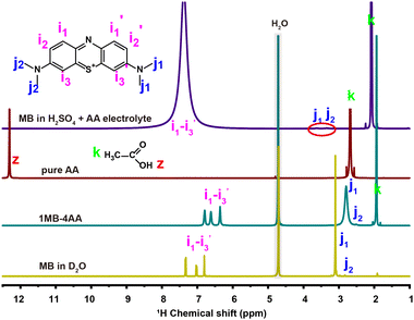
:![[thin space (1/6-em)]](https://www.rsc.org/images/entities/char_2009.gif) 4 at 20 °C without any other solvent (1MB-4AA, Fig. S1, ESI†). Eutectic electrolytes have been already proposed to increase the RASs concentration in our previous works.41–46 NMR spectra and differential scanning calorimetry (DSC) analysis (Fig. 1 and Fig. S2, S3, ESI†) have revealed that the strong interaction between the MB and AA molecules leads to the eutectic electrolyte. The MB concentration in the 1MB-4AA electrolyte is >1.9 M. Moreover, the increased H2SO4 concentration in the electrolytes could be beneficial to the MB solubility, which can be attributed to the hydrophilic protonated amino group in acidic solution (Fig. S4 and S5, ESI†). However, there is an optimal range for the H2SO4 content, and a concentration of 3 M H2SO4 electrolyte was selected when considering the redox potential and solubility of the MB molecules.
4 at 20 °C without any other solvent (1MB-4AA, Fig. S1, ESI†). Eutectic electrolytes have been already proposed to increase the RASs concentration in our previous works.41–46 NMR spectra and differential scanning calorimetry (DSC) analysis (Fig. 1 and Fig. S2, S3, ESI†) have revealed that the strong interaction between the MB and AA molecules leads to the eutectic electrolyte. The MB concentration in the 1MB-4AA electrolyte is >1.9 M. Moreover, the increased H2SO4 concentration in the electrolytes could be beneficial to the MB solubility, which can be attributed to the hydrophilic protonated amino group in acidic solution (Fig. S4 and S5, ESI†). However, there is an optimal range for the H2SO4 content, and a concentration of 3 M H2SO4 electrolyte was selected when considering the redox potential and solubility of the MB molecules.
The 1H NMR of the MB molecule in 3 M H2SO4 solution becomes complex. The proton signals are significantly weakened compared with the one in D2O, especially for the j1 and j2 peaks of the N-methyl protons groups (R-N-(CH3)2). The i1, i2, and i3 peaks of the benzene ring protons turned into a broad peak at 7.5 ppm (Fig. 1). This could be attributed to the rapid active proton exchange after the protonation of the amino groups at high acidic concentration.47–49
The MB molecule will be protonated firstly when the proton concentration is above 1 M.50 Therefore, the redox reaction of the MB electrolyte actually began with the protonated MB molecule at the strong acidic solution (3 M H2SO4). For the protonated MB molecule (MBH2+), the central nitrogen is protonated and the primary cation in the MB will prefer the side amino nitrogen position to bring about a strong equivalent resonance.51,52 The electron transfer numbers of the redox reaction are ∼2.0, as detected by the rotating ring-disc electrode (RRDE) measurement (Fig. S6, ESI†), and was almost consistent at different AA contents. The whole redox process of the MB electrolyte in 3 M H2SO4 solution can be as follows: the MBH2+ molecule receives two electrons and two protons to generate the reduced state the HMBH22+ molecule (pKa = ∼3.853) (Scheme 2).
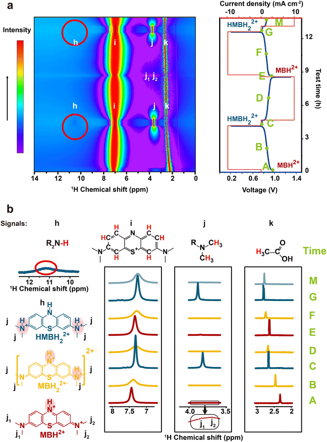
To further reveal the redox mechanism of the MB molecules, the in situ pseudo-2D 1H NMR spectra of MB as a function of electrochemical cycling in a V-MB single cell were obtained in real cells. It should be noted that the low current density of 10 mA cm−2 was applied to ensure that the redox reaction was completed, and one cycle lasted nearly 9 hours. Fig. 2 and Fig. S7, S8 (ESI†) present the 1H NMR spectra of the MB electrolyte as a function of electrochemical cycling. During the discharging process (A–C), the intensity of peak i decreased sharply at first, and then dropped to the minimum at ∼50% state of charge (SOC, B). The weak peaks j1 and j2 were detected only before the discharging (A). When continuing discharging (B-C), the intensity of the peak i was recovered, and the peak j gradually appeared. At the end of the discharging process (C), both peaks i and j reached the highest intensities and a new peak h representing the (R2N-H) group in HMBH22+ appeared. The single sharp peak j in the HMBH22+ indicates its highly symmetric structure, resulting in the two N methyl groups possessing identical chemical environments.54 Meanwhile, the changes of the 1H NMR spectra are reversible during the charging process (C–E), indicating the reversible redox reaction of the MB molecule. It should be noted that for the in situ experiment, slight peak shifts were also observed during the discharging process. The proton signal i of MB moved towards lower chemical shift, while the proton signal j of MB and signal k of AA moved towards higher chemical shifts. These shifts were difficult to fully recover during the next charging process. Compared with the unchanged chemical shift in the ex situ NMR spectra (Fig. S9, ESI†), it could be inferred that these variations in chemical shifts may be ascribed to the effect of the electric field during the in situ environment.
One more thing is that the width of peak i also shows a periodic change with the cell SOCs. It became the broadest at 50% SOC (B, D, and F), and then narrowed. The width was the narrowest at the end of the charging and discharging process. The change could be due to the presence of a paramagnetic shielding effect by radicals in the MB electrolyte during cycling.48 Therefore, the ex situ EPR spectrum of the MB electrolytes was tested to detect the radical formation after 20 cycles in the 0.1 M MB/SWO (silicotungstic acid) flow cell (Fig. 3(a)). The strong EPR signal of the crossed V ions causes serious interference in the MB spectrum. The crossover of the SWO with large structure size can be effectively inhibited.21 Therefore, the V anolyte was replaced by the SWO electrolyte here to eliminate the effect of the crossed V ions. It can be observed that the strong radical signal with the hyperfine coupling features was detected at 50% SOC MB electrolyte (Fig. 3(a) and Fig. S10, ESI†). Such signals can originate from the comproportionation reaction between the oxidized MBH2+ and the reduced HMBH22+ in the electrolyte, leading to the intermediate MBH22+˙ radicals as follows (Scheme 3).
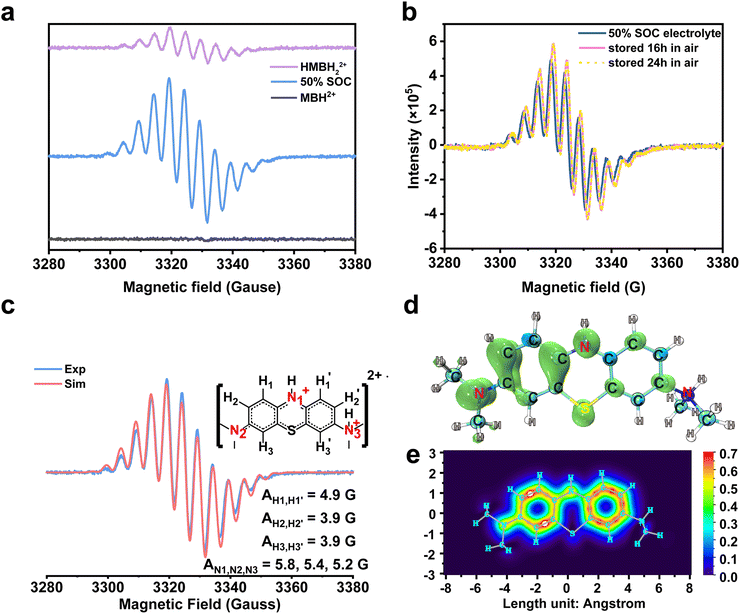 | ||
| Fig. 3 Ex situ EPR spectra acquired during the electrochemical cycling and DFT calculation of the MBH22+˙ radical. (a). Ex situ EPR spectra of different SOC catholytes and their individual associated components are MBH2+, MBH22+˙ and HMBH2+. (b). The sample was acquired at 50% SOC in a full cell with 0.1 M MB/SWO (silicotungstic acid) electrolyte. It was stored in air, and then its radical intensity was measured from the EPR spectra after 0 h, 16 h and 24 h. (c). The experiment and simulation EPR spectra of 100 mM MB. The molecular structure used for the fit is shown to the right, together with the proton labels. Their associated hyperfine coupling constants (AN1,N2,N3 = 5.8, 5.4, 5.3 G and AH1,H1′ = 4.9 G, AH2,H2′ = 3.9 G, AH3,H3′ = 3.9 G) extracted from the simulation.1 The value of the g-factors for MBH22+˙ is 2.00372. (d) and (e). The images of the electron spin density and the π-electron localized orbital locator (LOL) of the MBH22+˙ radical. | ||
 | ||
| Scheme 3 The comproportionation reaction between the oxidized MBH2+ and the reduced HMBH22+ in the 3 M H2SO4 solution. | ||
The concentration of the MBH22+˙ radicals in the electrolyte was controlled by the reaction 1 equilibrium constant and SOC. Hence, HMBH22+ reacted with MBH2+ to form the MBH22+˙ radical quickly during cycling. The concentration of MBH22+˙ increased gradually and reached the maximum at 50% SOC (B, D, and F). The electron delocalization over the MBH22+˙ radicals had an effect on the proton resonances of peak i, thereby leading to its periodic change in width.48,55 The intense signal changes of peaks i and j could be associated with the concentrations of the MBH22+˙ radical and HMBH22+.
The obtained pure HMBH22+ solution was a light yellow transparent solution at the low current density of 40 mA cm−2. Both galvanostatic and potentiostatic models were applied to ensure the fully reduction/oxidation of MB during each cycle. However, it was becoming Cambridge blue in air rapidly. The blue color depth remained almost unchanged for a long time, indicating the slight autoxidation of the HMBH22+ molecule. This was why the weak radical signals were observed in the HMBH22+ electrolyte56 (Fig. 3(a)).
The MBH22+˙ radical was previously reported to have a short lifetime in some nonaqueous systems.57,58 Herein, all MB electrolytes were placed in air over several hours without any protection before the ex situ EPR measurement. In order to validate the stability of the MBH22+˙ radicals, 0.1 M MB electrolyte of 50% SOC were separately rested in air for ∼16 h and 24 h. The EPR spectra of the MBH22+˙ radical at different times are highly coincident with each other, as displayed in Fig. 3(b), which reveals the structural stability of the MBH22+˙ radical and its oxygen resistance. As discussed above, the protonation and rearrangement of the molecular skeleton were observed for MB in the strongly acidic solution.59–61 According to the hyperfine coupling constants extracted from the simulation in Fig. 3(c), the values of AN1, AN2, and AN3 are very close. Furthermore, the hyperfine coupling constants of the H atoms on two benzene rings are also nearly appropriate with the N atoms. This means that the odd electron can be distributed on the whole skeleton.62 The DFT simulation in Fig. 3(d) and (e) also revealed that the electron spin was delocalized within the two entire benzene rings and the conjugated N atom, corresponding to the π-electron localized orbital locator (LOL) of the MBH22+˙ radical. For comparison, the electron spin density and LOL of the 2,6-dihydroxyanthraquinone (DHAQ) radical were also calculated (Fig. S11, ESI†). It can be clearly seen that the π-electron in the MBH22+˙ radical are more delocalized on the benzene ring with the protonated tertiary ammonium group, which could promote the persistence of the radical (Table S1, ESI†).63 The stable MBH22+˙ radical in the electrolyte is quite different from other reported air-sensitivity organic RASs.64 Combined with the reversible 1H spectra and steady MBH22+˙ radical signals in the open environment, the MB electrolyte would be an air-stable organic electrolyte for high-performance FBs.
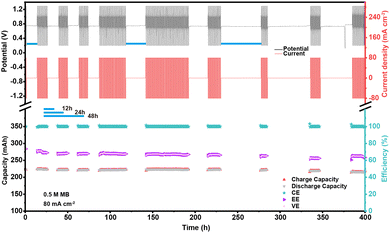
To validate the chemical and electrochemical stability of the MB electrolyte, a pausing cycling test of the V-MB cell was carried out by resting at complete discharge step for different times. The voltage–time and current–time curves and performance of the V-MB cells were operated for 400 hours with a galvanostatic method at a current density of 80 mA cm−2 (Fig. 4). When increasing the pausing intervals from 12 hours to 24 and 48 hours, the cell displayed a minor negligible capacity and efficiency decay with the cell CE of almost 99.8%. This indicated that the HMBH22+ electrolyte exhibited excellent chemical and electrochemical stability and little autoxidation. The fluctuating and slight decrease of the capacities and efficiencies during cycling (Fig. 4(b) and S12a, b, ESI†) can be attributed to the environmental temperature change and V ions crossover. The FTIR spectra revealed that there was no obvious change for the MB electrolyte after 3 days (72 h) when compared to the initial one (Fig. S12c, ESI†). Even when evaluated at 50 °C, the cell still exhibited stable performance (Fig. S13, ESI†). This demonstrated that the MB electrolyte possessed outstanding chemical and electrochemical stability. The capacities reached 49.9, 64.3, and 75.2 A h L−1 at 1.0 M, 1.3 M, and 1.5 M MB electrolytes (Fig. S14, ESI†), which is comparable to the best reported values in AOFBs.28,31,65
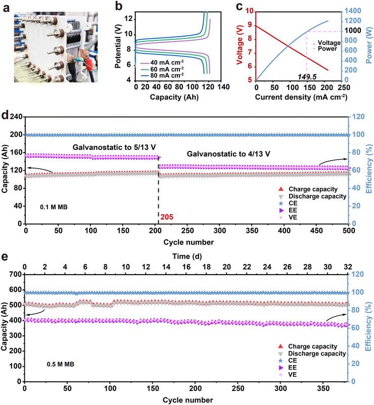
Furthermore, a V-MB stack was assembled to evaluate the practical application of the MB electrolyte. A total of 10 units flow stack with an area of 1000 cm2 was assembled, and 0.1 M and 0.5 M MB (5.25 M AA and 3 M H2SO4) electrolytes were each tested in the stack. (Fig. 5 and Fig. S15, S16, ESI†). As shown in Fig. 5(b), the 0.1 M V-MB stack exhibited discharge capacities of 121, 117 and 112 Ah with CE and energy efficiencies (EE) of 99.6%, 99.7%, 99.8% and 82.5%, 75.1%, 69.2% at the current densities of 40, 60, and 80 mA cm−2 in the initial cycle (Fig. 4(b)), respectively. The utilization of the MB electrolyte at 40 mA cm−2 is ∼95%. Moreover, the instantaneous discharge power of the stack batteries can be over 1 kW (1.26 kW) (Fig. 5(c)). As shown in Fig. 5(d), the stack also exhibited a stable long period cycle at 80 mA cm−2 for over 500 cycles and no new 1H NMR signals were observed before and after cycling, representing the high stability of the MB electrolyte in the stack (Fig. S17, ESI†). The shift of the benzene ring of MB was due to the increase in the acidity of the catholyte, which resulted from the water migrating from the cathode to anode side during the cycling. Furthermore, the stack based on the 0.5 M MB electrolyte also achieved a stable long-life cycle performance after 380 cycles (∼32 days) with the capacity of ∼510 A h at 50 mA cm−2 (Fig. 5(e)). The gradual decrease of EE with the cycling from the initial 69.3% to 63.4% could be derived from the oxidation of V(II) by air and MB adsorption on the membrane, as shown in Fig. S12 and S18 (ESI†).28,35 As far as we know, this is the first FB stack reported based on the air-stable organic electrolyte. The stable cycling performance of the V-MB stack indicated that the aqueous organic MB electrolyte can definitely be an encouraging choice for the development of large-scale AOFBs.
The MB electrolyte was further tested by the accelerated experiment at high temperature to assess the working condition of the MB electrolyte. The electrolyte was collected into the tank, and heated at high temperature for different times after the 1st cycle. The HMBH22+ electrolyte displayed only a small capacity decrease in the first cycle after being stored at 50 °C for 3 days and even 70 °C for 3 days twice (Fig. 6(a)). There was little change on the CV curves of the reduced state before and after storing at 70 °C for 6 days, as shown in Fig. S19 (ESI†). The slight capacity decay could be derived from the autoxidation of HMBH22+ and generates MBH22+˙ radicals, corresponding to the signal of the EPR spectrum of the HMBH22+ electrolyte (Fig. 3(a)). Meanwhile, the capacity can recover after the 1st cycle, indicating that both the reduced state HMBH22+ and the MBH22+˙ radicals were stable in air and at high temperatures. The increased polarization and slight capacity decay could be due to the drying membrane and the slight loss of electrolyte when the electrolyte was transferred to the heater. The pure MB electrolyte involves complex changes when heating at high temperature. The first discharge capacity of the pure MB electrolyte was only 55% (125 mA h) after 50 °C for 3 days. However, the capacity recovered after the 1st cycle to 227 mA h. Meanwhile, there was a new reversible charge/discharge platform at high voltage. It can be inferred that both MB reduction and partial oxidation occurred at high temperature (Fig. 6(b)). When elevated to 70 °C, the decomposition of the MB molecules occurred quickly, and the discharge capacity dropped to 85 mA h with a new platform at lower voltage (0.4 V from CV redox peak) at the 1st cycle. There is another new platform at higher redox voltage (0.77 V) in the next cycle. Surprisingly, both new two platforms are reversible, and the cell exhibited a little capacity decay after the 1st cycle with a CE value of almost 100%. A longer heating time and new longer platforms appeared, which is consistent with the CV curve change of MB at 70 °C (Fig. 6(c) and Fig. S16, ESI†). The slight capacity change of the MB electrolyte after high temperature treatment could be attributed to the remaining redox center of the molecule even after decomposition, suggesting that MB derivatives with different redox potentials could be achieved by rational molecular engineering in the future. A half-life period curve was obtained based on the CV curves of the oxidation peak current of MB at 0.59 V to determine the decay rate of the MB molecules. The accelerated half-life period can be about 247 hours (∼10.3 days) at 70 °C (Fig. 6(d)).
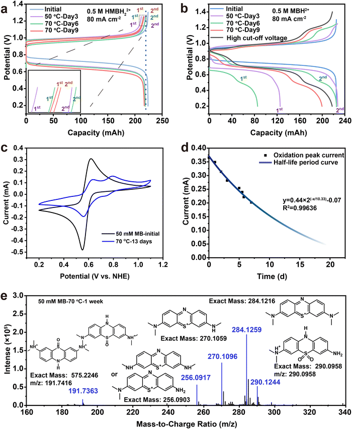 | ||
| Fig. 6 Evaluation of the stability of the MB electrolyte at high temperature. Charge–discharge profiles of MB-V FBs: a reduction and b oxidation after 50 °C and 70 °C treatment for different times. Inset in a: The enlarged region at the end of the charging curves. Curves 1 and 2 were the first and second discharge cycles after pausing, respectively. (c) CV curve of 50 mM MB changes after high temperature. (d) The half-life period curve plot of 50 mM MB at 70 °C based on the peak current of 0.59 V. (e) The mass spectrum extracted from the total ion chromatogram (TIC) (Fig. S16, ESI†) from 5.426 min to 7.986 min displays the possible formation of the MB molecule's decay and MB dimer derivatives after one week at 70 °C. | ||
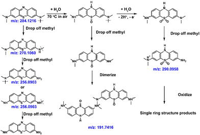
Liquid chromatography-mass spectroscopy (LC-MS) was used to detect the decomposition compounds of the MB molecules at 70 °C (Fig. 6(e) and Fig. S17, ESI†). Scheme 4 illustrates the most possible mechanism of the side reactions at high temperature.66,67 The methyl groups on the tertiary amine would fall off at high temperature (m/z: 270.1060, m/z: 256.0903). Meanwhile, a dimer formed after demethylation (m/z:191). The MB sulfoxide form was also found (m/z: 290),68 which contributes to the newly generated high redox potential. Combined with its reversible redox performance shown in Fig. 6(c), the newly generated high-potential molecule also shows great promise, and will be studied in the future.
Conclusions
The analysis of the redox reaction mechanism of the MB electrolyte based on the in situ NMR and ex situ EPR spectra reveals that the oxygen-resistant MBH22+˙ radicals and the reduced state HMBH22+ play an important role in the reversibility of the MB electrolyte, which can be attributed to the strong spin delocalization over the MB skeleton in the acidic solution. The pausing (12–48 h) cycling experiment of the V-MB single cell demonstrated that the MB electrolyte exhibited excellent chemical and electrochemical stability in air. The 10 units, 1000 cm2 FB stack based on the MB electrolyte exhibited a discharge power of higher than 1 kW and a stable capacity after more than one month of cycling at 0.5 M. Moreover, the molecule-accelerated attenuation testing at high temperature showed that the reduced state HMBH22+ exhibited superior stability. Although the side reactions of the pristine MB were severe at 70 °C, most of the decomposed molecules still retained the redox center with only a slight capacity decay. The excellent performance and stable MB electrolyte in this work paves the way towards the practicability of high-performance AOFBs for large-scale energy storage.Author contributions
Yonghui Zhang: investigation, writing the original draft. Fan Li: NMR analysis and discussion. Tianyu Li: DFT simulation. Mengqi Zhang: investigation and discussion. Zhizhang Yuan: flow stack evaluation and discussion of the results. Guangjin Hou: discussion of the results. Jie Fu: supervision. Changkun Zhang: conceptualization, writing – review & editing, supervision. Xianfeng Li: conceptualization, writing – review & editing, supervision. All authors reviewed the manuscript.Conflicts of interest
The authors declare no conflict of interest.Acknowledgements
This work was supported by the China Natural Science Foundation (Grant no. 22279133 and U1808209) and the International Partnership Program of the Chinese Academy of Sciences Grant no. 121421KYSB20210028 and National Key R&D Program of China (2022YFB2405000). We thank Dr Shengfa Ye for his kind help in the EPR spectra discussions, and Dr Guang Zeng for his help in the EPR simulation and discussion.Notes and references
- E. W. Zhao, E. Jonsson, R. B. Jethwa, D. Hey, D. Lyu, A. Brookfield, P. A. A. Klusener, D. Collison and C. P. Grey, J. Am. Chem. Soc., 2021, 143, 1885–1895 CAS.
- S. Chu, Y. Cui and N. Liu, Nat. Mater., 2017, 16, 16–22 Search PubMed.
- S. Chu and A. Majumdar, Nature, 2012, 488, 294–303 CAS.
- M. Z. Jacobson, M. A. Delucchi, Z. A. F. Bauer, S. C. Goodman, W. E. Chapman, M. A. Cameron, C. Bozonnat, L. Chobadi, H. A. Clonts, P. Enevoldsen, J. R. Erwin, S. N. Fobi, O. K. Goldstrom, E. M. Hennessy, J. Liu, J. Lo, C. B. Meyer, S. B. Morris, K. R. Moy, P. L. O’Neill, I. Petkov, S. Redfern, R. Schucker, M. A. Sontag, J. Wang, E. Weiner and A. S. Yachanin, Joule, 2017, 1, 108–121 Search PubMed.
- L. Meng, Y. Zhang, X. Wan, C. Li, X. Zhang, Y. Wang, X. Ke, Z. Xiao, L. Ding, R. Xia, H. L. Yip, Y. Cao and Y. Chen, Science, 2018, 361, 1094–1098 CAS.
- Q. Dai, F. Xing, X. N. Liu, D. Q. Shi, C. Z. Deng, Z. M. Zhao and X. F. Li, Energy Environ. Sci., 2022, 15, 1594–1600 CAS.
- R. F. Service, Science, 2018, 362, 508–509 CAS.
- Z. Z. Yuan, L. X. Liang, Q. Dai, T. Y. Li, Q. L. Song, H. M. Zhang, G. J. Hou and X. F. Li, Joule, 2022, 6, 884–905 CAS.
- Z. Yuan, Y. Yin, C. Xie, H. Zhang, Y. Yao and X. Li, Adv. Mater., 2019, 31, e1902025 Search PubMed.
- H. Zhang, Nature, 2014, 508, 319 Search PubMed.
- T. Y. Li, F. Xing, T. Liu, J. W. Sun, D. Q. Shi, H. M. Zhang and X. F. Li, Energy Environ. Sci., 2020, 13, 4353–4361 CAS.
- B. Hu, C. DeBruler, Z. Rhodes and T. L. Liu, J. Am. Chem. Soc., 2017, 139, 1207–1214 CAS.
- M. A. Goulet, L. Tong, D. A. Pollack, D. P. Tabor, S. A. Odom, A. Aspuru-Guzik, E. E. Kwan, R. G. Gordon and M. J. Aziz, J. Am. Chem. Soc., 2019, 141, 8014–8019 CAS.
- L. Zhang, R. Feng, W. Wang and G. Yu, Nat. Rev. Chem., 2022, 6, 524–543 Search PubMed.
- J. Winsberg, T. Hagemann, T. Janoschka, M. D. Hager and U. S. Schubert, Angew. Chem., Int. Ed., 2017, 56, 686–711 CAS.
- J. Luo, B. Hu, M. Hu, Y. Zhao and T. L. Liu, ACS Energy Lett., 2019, 4, 2220–2240 CAS.
- C. Zhang, L. Zhang, Y. Ding, S. Peng, X. Guo, Y. Zhao, G. He and G. Yu, Energy Storage Mater., 2018, 15, 324–350 Search PubMed.
- D. G. Kwabi, K. Lin, Y. Ji, E. F. Kerr, M.-A. Goulet, D. De Porcellinis, D. P. Tabor, D. A. Pollack, A. Aspuru-Guzik, R. G. Gordon and M. J. Aziz, Joule, 2018, 2, 1894–1906 CAS.
- K. Lin, Q. Chen, M. R. Gerhardt, L. Tong, S. B. Kim, L. Eisenach, A. W. Valle, D. Hardee, R. G. Gordon, M. J. Aziz and M. P. Marshak, Science, 2015, 349, 1529–1532 CAS.
- B. Huskinson, M. P. Marshak, C. Suh, S. Er, M. R. Gerhardt, C. J. Galvin, X. Chen, A. Aspuru-Guzik, R. G. Gordon and M. J. Aziz, Nature, 2014, 505, 195–198 CAS.
- W. Q. Liu, Z. M. Zhao, T. Y. Li, S. H. Li, H. M. Zhang and X. F. Li, Sci. Bull., 2021, 66, 457–463 CAS.
- J. Winsberg, C. Stolze, A. Schwenke, S. Muench, M. D. Hager and U. S. Schubert, ACS Energy Lett., 2017, 2, 411–416 CAS.
- W. Zhou, W. Liu, M. Qin, Z. Chen, J. Xu, J. Cao and J. Li, RSC Adv., 2020, 10, 21839–21844 CAS.
- B. Hu, C. Debruler, Z. Rhodes and T. Liu, J. Am. Chem. Soc., 2017, 139, 1207–1214 CAS.
- H. Li, H. Fan, B. Hu, L. Hu, G. Chang and J. Song, Angew. Chem., Int. Ed., 2021, 60, 26971–26977 CAS.
- S. Hu, T. Li, M. Huang, J. Huang, W. Li, L. Wang, Z. Chen, Z. Fu, X. Li and Z. Liang, Adv. Mater., 2021, 33, 2005839 CAS.
- W. Liu, Y. Liu, H. Zhang, C. Xie, L. Shi, Y.-G. Zhou and X. Li, Chem. Commun., 2019, 55, 4801–4804 CAS.
- A. Hollas, X. Wei, V. Murugesan, Z. Nie, B. Li, D. Reed, J. Liu, V. Sprenkle and W. Wang, Nat. Energy, 2018, 3, 508–514 CAS.
- J. Xu, S. Pang, X. Wang, P. Wang and Y. Ji, Joule, 2021, 5, 2437–2449 CAS.
- C. Zhang, Z. Niu, S. Peng, Y. Ding, L. Zhang, X. Guo, Y. Zhao and G. Yu, Adv. Mater., 2019, 31, 1901052 Search PubMed.
- R. Feng, X. Zhang, V. Murugesan, A. Hollas, Y. Chen, Y. Shao, E. Walter, N. P. N. Wellala, L. Yan, K. M. Rosso and W. Wang, Science, 2021, 372, 836–840 CAS.
- T. P. Nguyen, A. D. Easley, N. Kang, S. Khan, S. M. Lim, Y. H. Rezenom, S. Wang, D. K. Tran, J. Fan, R. A. Letteri, X. He, L. Su, C. H. Yu, J. L. Lutkenhaus and K. L. Wooley, Nature, 2021, 593, 61–66 CAS.
- K. Lin, R. Gómez-Bombarelli, E. S. Beh, L. Tong, Q. Chen, A. Valle, A. Aspuru-Guzik, M. J. Aziz and R. G. Gordon, Nat. Energy, 2016, 1, 16102–16109 CAS.
- S. Pang, X. Wang, P. Wang and Y. Ji, Angew. Chem., Int. Ed., 2021, 60, 5289–5298 CAS.
- D. Chen, G. Liu, J. Liu, C. Zhang and Z. Yuan, J. Energy Chem., 2022, 68, 247–254 CAS.
- X. Li, P. Gao, Y.-Y. Lai, J. D. Bazak, A. Hollas, H.-Y. Lin, V. Murugesan, S. Zhang, C.-F. Cheng, W.-Y. Tung, Y.-T. Lai, R. Feng, J. Wang, C.-L. Wang, W. Wang and Y. Zhu, Nat. Energy, 2021, 6, 873–881 CAS.
- C. Xie, W. Xu, H. Zhang, X. Hu and X. Li, Chem. Commun., 2018, 54, 8419–8422 CAS.
- C. Zhang and X. Li, Curr. Opin. Electrochem., 2021, 30, 100836 CAS.
- Z. Zhao, C. Zhang and X. Li, J. Energy Chem., 2022, 67, 621–639 CAS.
- H. Fu, C. Zhang, H. Wang, B. Du, J. Nie, J. Xu and L. Chen, J. Power Sources, 2022, 545, 231905 CAS.
- C. Zhang, H. Chen, Y. Qian, G. Dai, Y. Zhao and G. Yu, Adv. Mater., 2021, 33, 2008560 CAS.
- C. Zhang, Y. Ding, L. Zhang, X. Wang, Y. Zhao, X. Zhang and G. Yu, Angew. Chem., Int. Ed., 2017, 56, 7454–7459 CAS.
- C. Zhang, Y. Qian, Y. Ding, L. Zhang, X. Guo, Y. Zhao and G. Yu, Angew. Chem., Int. Ed., 2019, 58, 7045–7050 CAS.
- C. Zhang, Z. Niu, Y. Ding, L. Zhang, Y. Zhou, X. Guo, X. Zhang, Y. Zhao and G. Yu, Chem, 2018, 4, 2814–2825 CAS.
- C. Zhang, L. Zhang and G. Yu, Acc. Chem. Res., 2020, 53, 1648–1659 CAS.
- C. Zhang, L. Zhang, Y. Ding, X. Guo and G. Yu, ACS Energy Lett., 2018, 3, 2875–2883 CAS.
- B. Mezari, P. C. Magusin, S. M. Almutairi, E. A. Pidko and E. J. Hensen, J. Phys. Chem. C, 2021, 125, 9050–9059 CAS.
- E. W. Zhao, E. Jónsson, R. B. Jethwa, D. Hey, D. Lyu, A. Brookfield, P. A. A. Klusener, D. Collison and C. P. Grey, J. Am. Chem. Soc., 2021, 143, 1885–1895 CAS.
- S. Granick, L. Michaelis and M. P. Schubert, Science, 1939, 90, 422–423 CAS.
- A. Katafias, P. Kita, G. Wrzeszcz and A. Mills, Transition Met. Chem., 2007, 32, 31–37 CAS.
- G. N. Lewis and J. Bigeleisen, J. Am. Chem. Soc., 1943, 65, 1144–1150 CAS.
- G. Schwarzenbach and L. Michaelis, J. Am. Chem. Soc., 1938, 60, 1667–1678 CAS.
- O. S. Ksenzhek, S. A. Petrova and M. V. Kolodyazhny, Bioelectrochem. Bioenerg., 1977, 4, 346–357 CAS.
- Z. Tie, S. Deng, H. Cao, M. Yao, Z. Niu and J. Chen, Angew. Chem., Int. Ed., 2022, 134, e202115180 Search PubMed.
- E. W. Zhao, T. Liu, E. Jónsson, J. Lee, I. Temprano, R. B. Jethwa, A. Wang, H. Smith, J. Carretero-González, Q. Song and C. P. Grey, Nature, 2020, 579, 224–228 CAS.
- A. Mills and J. Wang, J. Photochem. Photobiol., A, 1999, 127, 123–134 CAS.
- J. A. Caram, J. M. Suárez, A. M. Gennaro and M. V. Mirifico, Electrochim. Acta, 2015, 164, 353–363 CAS.
- R. Zhan, S. Song, Y. Liu and S. Dong, J. Chem. Soc., Faraday Trans., 1990, 86, 3125–3127 CAS.
- F. W. Heineken, M. Bruin and F. Bruin, J. Chem. Phys., 1962, 37, 1479–1482 CAS.
- T. Stanoeva, D. Neshchadin, G. Gescheidt, J. Ludvik, B. Lajoie and S. N. Batchelor, J. Phys. Chem. A, 2005, 109, 11103–11109 CAS.
- O. F. Griffith and C. P. Poole, Spectrochim. Acta, Part A, 1969, 25, 1463–1469 CAS.
- X.-H. Liu, H.-Y. Yu, J.-Y. Huang, J.-H. Su, C. Xue, X.-T. Zhou, Y.-R. He, Q. He, D.-J. Xu, C. Xiong and H.-B. Ji, Chem. Sci., 2022, 13, 9560–9568 CAS.
- K. Pavlíková and P. Ševčík, React. Kinet. Catal. Lett., 2000, 69, 91–94 Search PubMed.
- D. G. Kwabi, Y. Ji and M. J. Aziz, Chem. Rev., 2020, 120, 6467–6489 CAS.
- Y. Liu, M.-A. Goulet, L. Tong, Y. Liu, Y. Ji, L. Wu, R. G. Gordon, M. J. Aziz, Z. Yang and T. Xu, Chem, 2019, 5, 1861–1870 CAS.
- Y. Gong, J. Wang, Z. Cheng, Z. Han, X. Zhao, B. Chai and Y. Han, Chin. Chem. Lett., 2022 DOI:10.1016/j.cclet.2022.05.049.
- Q. Wang, S. Tian and P. Ning, Ind. Eng. Chem. Res., 2014, 53, 643–649 CAS.
- M. D. Casselman, A. P. Kaur, K. A. Narayana, C. F. Elliott, C. Risko and S. A. Odom, Phys. Chem. Chem. Phys., 2015, 17, 6905–6912 CAS.
Footnote |
| † Electronic supplementary information (ESI) available: Electrochemical study and battery test details. See DOI: https://doi.org/10.1039/d2ee03051a |
| This journal is © The Royal Society of Chemistry 2023 |

