 Open Access Article
Creative Commons Attribution 3.0 Unported Licence
Butylamine functionalized graphene oxide: experimental and DFT studies on the corrosion inhibition efficiency of the MgAZ13 alloy in a 3.5% NaCl environment
N.
Palaniappan
 *a,
Ivan
Cole
 *b,
A.
Kuznetsov
 c,
F.
Caballero-Briones
d and
Sivakumar
Manickam
 e
e
aSchool of chemical science, Central University of Gujarat, India. E-mail: palaniappancecri@rediffmail.com
bECP, Adv. Manufacture and Fabrication, RMIT University, Australia. E-mail: ivan.cole@rmit.edu.au
cDepartment of Chemistry, Universidad Técnica Federico Santa Maria, Campus Vitacura, Santiago, Chile
dInstituto Politecnico, Nacional, Materials, and Technologies for Energy, Health, and Environment (GESMAT), CICATA Altamira, Altamira, Mexico
ePetroleum and Chemical Engineering, Faculty of Engineering, Universiti Teknologi Brunei, Bandar Seri Begawan, BE1410, Brunei Darussalam
First published on 5th January 2023
Abstract
A unique property of graphene oxide (GO)-based functionalized materials is their corrosion retardation. We have designed a butylamine functionalized GO material as a corrosion-resistant coating for magnesium alloys in a 3.5% NaCl environment. The functionalized materials were characterized by different spectroscopic techniques: Raman, FESEM (field emission scanning electron microscopy), TEM (transmission electron microscopy), XRD (X-ray powder diffraction), and FTIR (Fourier transform infrared spectroscopy). The electrochemical properties were evaluated by various electrochemical methods such as CV (cyclic voltammetry) and LSV (linear sweep voltammetry). The redox properties of the composite materials showed excellent electrochemical stability up to an applied voltage of 600 mV. The corrosion inhibition efficiency was obtained to be around 69%. The DFT (density functional theory) results support the experimental findings.
1. Introduction
Mg alloys play a significant role in developing new materials for specific applications in the airbus and automobile industries due to their lightweight. However, these alloys are undergo corrosion in open air and corrosive media. Alkyls with different chain lengths have been studied as corrosion-resistant materials due to their favourable surfactant properties.1 The higher concentration of inhibitor molecules results in increased inhibition efficiency, but with the increasing temperature, the inhibition efficiency is decreased because surfactant chains are less stable at higher temperatures.Corrosion inhibition using polyurethane-based triazole compounds was studied by Shin et al.2 They showed that for a larger alkyl chain length of polyurethane, the inhibition efficiency increased because of the polyurethane moieties promoting hydrophobic surface formation. Their results suggest that the inhibitor efficiency depends on the stability and electron donation abilities of the inhibitor structure. Shaban, in 2016, studied amide derivative corrosion inhibition for steel in acidic environments and concluded that with increased alkyl chain length, hydrophobicity and inhibition efficiency also increased. The loss of inhibition efficiency with the temperature increase was associated with the stability loss of amide structures.3 Catechol-based alkylamine corrosion inhibition was studied on Mg alloys in a 3.5% NaCl environment by Payra et al. The research revealed that catechol units and amine non-bonding electrons are chemisorbed on the Mg alloy surface, reducing corrosion rates.4 Furthermore, by theoretical methods, Bartley et al. studied the corrosion inhibition efficiency of the alkyl esters from methyl to octyl alkyl. It was concluded that with the increase in the alkyl chain length, the chemisorption increased due to the non-bonding electrons interacting with the active metal surface.5 Also, recently, plasma-based oxidation of the magnesium alloy coated with 2,5-pyridindicarboxylate as inhibitor molecules was reported. The corrosion inhibition was tested in a KOH/Na3PO4 mixture with a weight ratio of 2![[thin space (1/6-em)]](https://www.rsc.org/images/entities/char_2009.gif) :
:![[thin space (1/6-em)]](https://www.rsc.org/images/entities/char_2009.gif) 8. The inhibitor compound showed significant corrosion resistance compared with plasma-coated magnesium alloys.6 Corrosion inhibition using cysteine functionalized alkylamine derivatives was studied by Lee et al.7 It was suggested that the increase of the inhibitor concentration caused the inhibition efficiency to increase due to the ethoxy π-electrons covalently interacting with the mild steel surface. The study revealed that cysteine controlled both the anodic and cathodic reactions. Furthermore, Guo et al.8 demonstrated that adding Sr to magnesium alloys increased their stress corrosion resistance in biological media. The Sr-containing Mg alloys showed excellent biocompatibility. Keera investigated the corrosion inhibition of an alkylamine derivative on carbon steel at different water and oil ratios.9 The results suggested that the inhibition efficiency increased with the alkyl chain length. Furthermore, corrosion inhibition studies in the ammonium nitrate medium were performed by Wang et al. Their results suggested that upon adding ammonium nitrate, hydrogen evolution was stopped due to ammonium ions.10 The effect of adding arsenic to a magnesium alloy matrix on corrosion inhibition in chloride medium was studied by Birbilis et al. They showed that corrosion inhibition increased compared with those of pure magnesium alloys.11 Williams et al. showed that adding microelements to the alloy, such as Ge, Pb, and Sn, improved the corrosion resistance in 3.5% NaCl environments. They suggested that adding microelements controlled the anodic dissolution of magnesium alloys.12 Li-based magnesium alloy corrosion resistance was studied by Birbilis et al. They showed that the BCC crystal structures of the Li dopant improved the corrosion resistance in 1 M NaCl medium.13 Furthermore, Birbilis et al.14 also demonstrated that lanthanide phosphate formed a passivating coating on magnesium alloys, reducing the attack of heavy electrolytes in a chloride corrosion medium. Birbilis et al.15 showed that the hydrogen evolution of the alloy increased during the anodic polarization of Mg alloys. The lanthanum phosphate-coated magnesium alloy showed high protection in 1 M NaCl environments due to the lanthanum acting as a sacrificial electrode.16 The influence of the addition of iron impurities to the Mg alloy on the hydrogen evolution in the chloride medium was studied by Williams et al.17 It was shown by Raja et al. that by adding In3+ to Mg alloys, the corrosion rate decreased due to the passivation layer formed on the alloy surface.18 However, at elevated temperatures, alkylamine derivatives failed to inhibit corrosion due to the unstable structure of inhibitor molecules.
8. The inhibitor compound showed significant corrosion resistance compared with plasma-coated magnesium alloys.6 Corrosion inhibition using cysteine functionalized alkylamine derivatives was studied by Lee et al.7 It was suggested that the increase of the inhibitor concentration caused the inhibition efficiency to increase due to the ethoxy π-electrons covalently interacting with the mild steel surface. The study revealed that cysteine controlled both the anodic and cathodic reactions. Furthermore, Guo et al.8 demonstrated that adding Sr to magnesium alloys increased their stress corrosion resistance in biological media. The Sr-containing Mg alloys showed excellent biocompatibility. Keera investigated the corrosion inhibition of an alkylamine derivative on carbon steel at different water and oil ratios.9 The results suggested that the inhibition efficiency increased with the alkyl chain length. Furthermore, corrosion inhibition studies in the ammonium nitrate medium were performed by Wang et al. Their results suggested that upon adding ammonium nitrate, hydrogen evolution was stopped due to ammonium ions.10 The effect of adding arsenic to a magnesium alloy matrix on corrosion inhibition in chloride medium was studied by Birbilis et al. They showed that corrosion inhibition increased compared with those of pure magnesium alloys.11 Williams et al. showed that adding microelements to the alloy, such as Ge, Pb, and Sn, improved the corrosion resistance in 3.5% NaCl environments. They suggested that adding microelements controlled the anodic dissolution of magnesium alloys.12 Li-based magnesium alloy corrosion resistance was studied by Birbilis et al. They showed that the BCC crystal structures of the Li dopant improved the corrosion resistance in 1 M NaCl medium.13 Furthermore, Birbilis et al.14 also demonstrated that lanthanide phosphate formed a passivating coating on magnesium alloys, reducing the attack of heavy electrolytes in a chloride corrosion medium. Birbilis et al.15 showed that the hydrogen evolution of the alloy increased during the anodic polarization of Mg alloys. The lanthanum phosphate-coated magnesium alloy showed high protection in 1 M NaCl environments due to the lanthanum acting as a sacrificial electrode.16 The influence of the addition of iron impurities to the Mg alloy on the hydrogen evolution in the chloride medium was studied by Williams et al.17 It was shown by Raja et al. that by adding In3+ to Mg alloys, the corrosion rate decreased due to the passivation layer formed on the alloy surface.18 However, at elevated temperatures, alkylamine derivatives failed to inhibit corrosion due to the unstable structure of inhibitor molecules.
This study aims to demonstrate that the above problem can be overcome using the alkylamine functionalized graphene oxide (GO) derivative. The alkylamine functionalized GO showed significant resistance to the high-temperature corrosion medium due to the multilayer GO structures. The inhibition efficiency was 68% in a 3.5% NaCl medium. This is the first time that butylamine functionalized GO has been reported as a corrosion inhibitor for magnesium alloys.
2. Methods and materials
Natural graphite powder, H2O2, H2SO4, H3PO4, and THF (tetrahydrofuran) were obtained from Sigma Aldrich. GO synthesis was performed as follows: 40 mL of H2SO4 and 50 mL of H3PO4 were mixed in a 250 mL round bottom flask, and the reaction setup was kept in a 1000 mL ice beaker. 3 g of graphite flakes were added to the mixture of acids, followed by the slow addition of 3 mg of KMnO4.19,20 The reaction mixture temperature was increased, and after cooling down, the mixture was kept in reflux at 60 °C for 24 h. After 24 h, the reaction mixture was cooled to room temperature and centrifuged at 7000 rpm. The obtained black-coloured precipitate was dried at 80 °C for 24 h. The butylamine functionalized GO sheets were synthesized using 50 mg of GO and 20 mg of butylamine in a 100 mL round bottom flask with THF as a solvent. The mixture in the round bottom flask was kept at reflux at 60 °C for 24 h. After 24 h, the reaction mixture was centrifuged at 6000 rpm three times and washed with ethanol and deionized water. The final butylamine functionalized GO sheets were dried at 80 °C for 24 h.2.1 Characterization
The structural modification of butylamine functionalized GO was confirmed by different techniques. The chemical modification was characterized by IR spectroscopy utilizing a full scan ranging from 400 to 4000 cm−1. The microstructure was studied by FESEM (working distance of 6.4 mm and an applied voltage of 300 kV) and TEM (200 FEG Philips, accelerating voltage 200 kV). The crystallinity of the chemically modified sheet was studied using XRD (Bruker D8 Advance, Karlsruhe, Germany) with an X-ray source (Cu Kα at 40 kV and 40 mA, the X-ray angles were 5° to 80° in a step range of 0.02° and scanning from 5° to 80°). The carbon defects were studied by a WITec confocal Raman spectroscopy at 530 nm laser vibration. The electrochemical studies were carried out using a CHI920D 760E model device.2.2 Corrosion inhibition and electrochemical studies
The corrosion inhibition studies were carried out in a three-electrode system. The magnesium alloy as a working electrode was prepared by grinding with different grate silicon paper from 2000 to 300 μm. Then, the alloy was cleaned with deionized water and ethanol. The clean alloy was mounted with a cold cure material. The mounted alloys were coated with epoxy and GOBUA (GO butylamine) by conventional brush, with the coating material weight ratio of 2![[thin space (1/6-em)]](https://www.rsc.org/images/entities/char_2009.gif) :
:![[thin space (1/6-em)]](https://www.rsc.org/images/entities/char_2009.gif) 1 (polyamine used as a binder). The coated Mg alloys were immersed continuously for 5 days in a 3.5% NaCl medium. After 5 days, the corrosion inhibition efficiency was studied by the three-electrode method using Ag/AgCl as a reference electrode, 3 mm platinum wire as a counter electrode and Mg alloy as a working electrode at the scan rates of 10 mV s−1.21–23 The corrosion inhibition efficiency was evaluated based on eqn (1) and (2). The redox properties were studied in the above-described electrochemical station. However, in this case, a platinum disk electrode was used as a working electrode, and 1 M NaOH was used as an electrolyte.
1 (polyamine used as a binder). The coated Mg alloys were immersed continuously for 5 days in a 3.5% NaCl medium. After 5 days, the corrosion inhibition efficiency was studied by the three-electrode method using Ag/AgCl as a reference electrode, 3 mm platinum wire as a counter electrode and Mg alloy as a working electrode at the scan rates of 10 mV s−1.21–23 The corrosion inhibition efficiency was evaluated based on eqn (1) and (2). The redox properties were studied in the above-described electrochemical station. However, in this case, a platinum disk electrode was used as a working electrode, and 1 M NaOH was used as an electrolyte. | (1) |
 | (2) |
 | (3) |
2.3 Computational studies
We used the C44H16O6 GO model, with two –CO2H groups, two –OH groups, and one![[double bond, length as m-dash]](https://www.rsc.org/images/entities/char_e001.gif) O group. Butylamine was coordinated to this GO model through the
O group. Butylamine was coordinated to this GO model through the ![[double bond, length as m-dash]](https://www.rsc.org/images/entities/char_e001.gif) N group. We performed theoretical studies of this model, both neutral and protonated on the N
N group. We performed theoretical studies of this model, both neutral and protonated on the N![[double bond, length as m-dash]](https://www.rsc.org/images/entities/char_e001.gif) group, using the Gaussian 09 package, revision B.01.24 Calculations were performed using the hybrid DFT functional B3LYP20 and split-valence polarised basis set 6-31G*.25 We optimized the structures and calculated the frequencies. We performed NBO (Natural Bonding Orbital) and MO (Molecular Orbital) analyses of our models with the implicit effects from water taken into account (dielectric constant ε = 78.3553). Implicit solvent calculations were performed using the self-consistent reaction field IEF-PCM method26 (the UFF default model was employed in the Gaussian 09 package, with the electrostatic scaling factor α set to 1.0). For the global reactivity analysis, electrophilicity χ, global hardness η, global softness σ, and nucleophilicity ω were calculated based on eqn (4)–(7) (I is the ionization potential, and A is the electron affinity).
group, using the Gaussian 09 package, revision B.01.24 Calculations were performed using the hybrid DFT functional B3LYP20 and split-valence polarised basis set 6-31G*.25 We optimized the structures and calculated the frequencies. We performed NBO (Natural Bonding Orbital) and MO (Molecular Orbital) analyses of our models with the implicit effects from water taken into account (dielectric constant ε = 78.3553). Implicit solvent calculations were performed using the self-consistent reaction field IEF-PCM method26 (the UFF default model was employed in the Gaussian 09 package, with the electrostatic scaling factor α set to 1.0). For the global reactivity analysis, electrophilicity χ, global hardness η, global softness σ, and nucleophilicity ω were calculated based on eqn (4)–(7) (I is the ionization potential, and A is the electron affinity). | (4) |
 | (5) |
 | (6) |
 | (7) |
3. Results and discussion
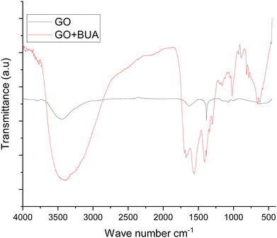
The FTIR spectra exhibit the butylamine functionalized GO (GOBUA), and GO functional groups are presented in Fig. 1. In the spectra of GO functional groups, the peak appearing at 3500 cm−1 suggests the hydroxyl groups of GO. The peak at 1229 cm−1 is associated with the epoxy groups in the GO matrix. Furthermore, the peak at 1680 cm−1 from C![[double bond, length as m-dash]](https://www.rsc.org/images/entities/char_e001.gif) O is associated with the GO bond stretching frequency. The peak at 1700 cm−1 is due to the carbonyl groups in the GO edge sheets. The peak at 1000 cm−1 is due to the epoxy groups in the GO matrix.27,28 The GOBUA functional group spectrum corresponding to the stretching frequency is shown in Fig. 1 as well. The edge hydroxyl groups of the GO sheet are at 3500 cm−1, and the stretching frequency of secondary amine is at 3300 cm−1. The alkyl chain peak at 2200 cm−1 is due to the secondary amine nitrogen covalently connected with GO sp2 carbon. The epoxy group peak disappears due to the alkyl chain nitrogen C
O is associated with the GO bond stretching frequency. The peak at 1700 cm−1 is due to the carbonyl groups in the GO edge sheets. The peak at 1000 cm−1 is due to the epoxy groups in the GO matrix.27,28 The GOBUA functional group spectrum corresponding to the stretching frequency is shown in Fig. 1 as well. The edge hydroxyl groups of the GO sheet are at 3500 cm−1, and the stretching frequency of secondary amine is at 3300 cm−1. The alkyl chain peak at 2200 cm−1 is due to the secondary amine nitrogen covalently connected with GO sp2 carbon. The epoxy group peak disappears due to the alkyl chain nitrogen C![[double bond, length as m-dash]](https://www.rsc.org/images/entities/char_e001.gif) N– bond formed on the GO matrix. The C–H bending stretching frequency appears at 1800 cm−1, as shown in Fig. 2A. The peak at 1300 cm−1 is associated with carbon disorder. The peak at 1500 cm−1 is associated with sp2 carbon vibrations.29,30 As shown in Fig. 2B, the composite material and GO crystallinity are shown at 2θ = 15° and 10°, suggesting chemically modified GO. The new peak at 2θ = 15° indicates GO modified by the alkylamine. The spectroscopic and XRD studies suggest that alkylamine covalently functionalized the GO sheets.31
N– bond formed on the GO matrix. The C–H bending stretching frequency appears at 1800 cm−1, as shown in Fig. 2A. The peak at 1300 cm−1 is associated with carbon disorder. The peak at 1500 cm−1 is associated with sp2 carbon vibrations.29,30 As shown in Fig. 2B, the composite material and GO crystallinity are shown at 2θ = 15° and 10°, suggesting chemically modified GO. The new peak at 2θ = 15° indicates GO modified by the alkylamine. The spectroscopic and XRD studies suggest that alkylamine covalently functionalized the GO sheets.31
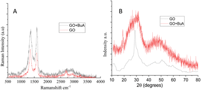 | ||
| Fig. 2 (A) Raman spectra of GO and butylamine functionalized GO and (B) XRD studies of GO and butylamine functionalized GO. | ||
3.1 Microstructural studies
Fig. 3A and B show the GO microstructure. In Fig. 3A, GO sheets show the presence of a few layers with a layer thickness of about 1 μm with no evidence of damage to the layer due to the presence of a mild oxidant. Fig. 3B provides clear evidence for a few layers of GO. The red colour indicates the layer thickness. Furthermore, Fig. 3C shows that granular-shaped layers are formed between graphene layers. This confirms that butylamine is covalently connected with GO sheets.32,33 The granular shape could improve the hydrophobic properties of GO sheets. Fig. 3D shows the morphology of alkylamine in blue color.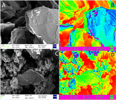 | ||
| Fig. 3 FESEM morphology: GO (A), GO (B), continuous GO sheet (C), and butylamine functionalized GO sheets (D). The blue color indicates butylamine incorporated GO sheets. | ||
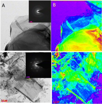
Fig. 4A shows the few-layer GO microstructures, which are polycrystalline. Fig. 4B shows a GO thin film in colour. Fig. 4C shows the formation of six-membered ring structures. Furthermore, the GOBUA sheet structure in colour is shown in Fig. 4D. The morphology studies suggest that GOBUA has few-layer GO sheets.
3.2 Electrochemical and hydrogen evolution studies
Fig. 5A and B show the electrochemical study results of butylamine functionalized GO. Fig. 5A illustrates the redox of GO and butylamine functionalized GO stability at different applied voltages, 20 mV to 30 mV, at a scan rate of 5 mV s−1. We employed an applied voltage window of ±10 mV. The peaks constantly appear without changes in the redox system due to the alkyl chain and non-bonding electrons of the nitrogen atom. We found that redox behaviour from 20 mV to 30 mV is due to the alkyl chain inductive effect. The redox peaks shown at 20 mV and 30 mV are due to the delocalization of non-bonding electrons of the GO matrix.34,35 Hence, when we try to find the stable redox behaviour at low applied voltage, the peak from 20 mV to 30 mV is due to the alkylamine conjugated bond delocalization. The redox behaviour suggests that the host molecule structure supports induced electron delocalization. The delocalization of π–π electrons of GO could support long-time electrochemical redox stability. Furthermore, we investigated hydrogen evolution by linear sweep voltammetry, as shown in Fig. 5B. The plot indicates that compared with GO, butyl amine functionalized GO showed high hydrogen evolution due to the edge functionalized alkyl chain inductive effect. At an increased applied voltage, 20 mV s−1, the hydrogen evolution increased due to the presence of the modified alkyl chains. The hydrogen evolution is increased due to the presence of the π-electron induced effect of the GO matrix upon guest molecules.36,37 We further tried to prove hydrogen evolution from the alkylamine functionalized GO using LSV methods.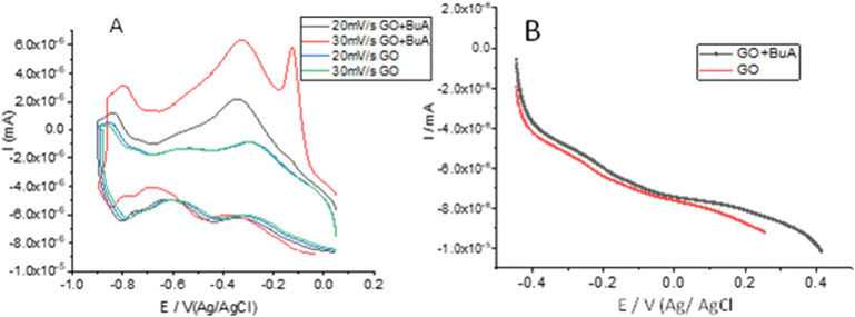 | ||
| Fig. 5 Cyclic voltammetry studies of GO and butyl amine functionalized GO sheets (A); linear polarisation studies of GO and butyl amine functionalized GO (B). | ||
3.3 Corrosion inhibition studies
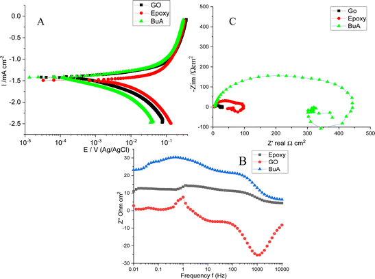
The potentiodynamic polarization and EIS results for epoxy-coated, butyl amine functionalized GO coated, and GO-coated Mg alloys are shown in Fig. 6A as reference. The GO-coated alloy showed −1.4206 mV less corrosion potential than the epoxy-coated alloy due to a graphene defect that allowed corrosive ions to attack the alloy surface. Moreover, its corrosion current of 0.0089 mA is high compared to that of the epoxy-coated alloy. The GO-coated alloy, as shown in Table 1, has high corrosion rates because there are no functional groups on the graphene oxide surface; it undergoes corrosion in corrosive environments.38,39 The epoxy-coated magnesium alloy generally shows a corroded surface and increased corrosion rates. Hence, the electrochemical results suggest that the epoxy-coated Mg alloy undergoes corrosion due to the weak adsorption of epoxy coating on the alloy surface. The corrosion potential decreased, and the corrosion current is 0.0050 mA increased and also failed to suppress anodic and cathode reactions due to the attack of corrosive ions on the alloy surface. The polarization values are decreased due to the corrosion environment's effect on the alloy. The corrosion rate of the epoxy-coated alloy is high compared to that of the amine-functionalized graphene oxide. However, butyl amine functionalized GO showed excellent corrosion resistance. The electrochemical results shown in Table 1 indicate that the corrosion potential increased and the corrosion current 0.0037 mA decreased due to the strong adsorption of the butyl amine functionalized GO on the metal alloys. The butyl amine functionalized graphene oxide illustrates NH-free chemisorption, leading to accepting negative chloride ions. Moreover, it controls the free chloride ion movement on the alloy surface.| S. No. | E Corr, (mV) | i Corr, (mA cm−2) | η, % | RS, Ω (cm2) | R ct, (Ω cm2) | C dl, (μF cm2) |
|---|---|---|---|---|---|---|
| GO | −1.4206 | 0.0089 | 5 | 35 | 4.186 ± 05 | |
| Epoxy | −1.4936 | 0.0050 | 43 | 10 | 140 | 3.788 ± 03 |
| GOBUA | −1.442 | 0.0037 | 83 | 5 | 445 | 2.275 ± 02 |
Furthermore, as shown in Fig. 6C, impedance spectroscopy studies suggest that high and low-frequency inductive impedance spectra and high-frequency capacitive impedance arc reveal a double layer between the alloy protective surface and the aggressive medium. Hence the inductive impedance arc is related to the low-frequency impedance around 0.01 Hz. These values determine the corrosion resistance of the coating materials and inhibitor molecules. However, the strong corrosion resistance of the coating materials is related to the large impedance values. If the semicircle is high, it is associated with alloy surface smoothness and corrosion resistance in corrosive environments. The solution resistance is always between the reference electrode and the working electrode and supports corrosion efficiency. Hence Rct is the charge transfer associated with the dissolution alloy by the attack of aggressive solution. Generally, the increased Rct values are related to high corrosion resistance, and low Rct values are associated with alloys undergoing corrosion in the environment. However, the Cdl values reveal the corrosion resistance of coating materials and inhibition efficiency. The GO low-frequency arc corresponds to the alloy undergoing corrosion. The Rct values are very low due to the corrosion ion penetration through the defect surface, and no chemisorption occurs on the surface, which leads to a low impedance arc.
In our case, butyl amine functionalized graphene oxide shows high Rct values compared with epoxy; it is associated with alloy surfaces not affected by corrosive ions due to the NH functional groups interacting with negative ions. Moreover, the butylamine functionalized graphene oxide Cdl value is less than 2.275 μf due to the functionalized graphene oxide trapped chloride ions by multilayer sheets. The epoxy-coated Mg alloys undergo corrosion due to the penetration of corrosive ions into the epoxy-coated Mg alloy surface.40,41 The semicircle is suppressed due to the Mg alloy being severely affected by the corrosive ions, as discussed in the microstructure. The Rct value of 140 Ω decreased due to the weak adsorption of epoxy coating on the alloy surface.
Furthermore, as shown in Fig. 6B, the impedance phase was suppressed by the penetration of corrosive ions into the epoxy coating.40,41 The impedance frequency spectra present low frequency compared with the butyl amine functionalized GO-coated Mg alloy, thus proving that the butyl amine functionalized GO interacts with the alloy surface. The high degree of angle suggests that the alloy does not undergo corrosion; in our case, butyl amine functionalized showed a high degree of angles and a smooth surface compared with epoxy-coated alloys.
3.4 Mg alloy microstructure
As shown in Fig. 7, grain boundary initiation is blocked by the effect of butyl amine functionalized GO sheets on Mg alloys.39 Upon immersion of the butyl amine functionalized GO coated Mg alloys in the corrosion medium, the edge coating peeled off from the alloy surface, the corrosive ions moved under the coating surface, and localized corrosion was initiated. However, at the moment of initiation, the butyl amine functionalized GO sheet blocked the penetration of ions.42,43 Furthermore, the alloy composition was investigated. The oxygen contents were less than the epoxy-coated alloy surface due to the slowdown of Mg alloy oxidation by the butyl amine functionalized GO sheet.44 Other elemental contents were not affected because butyl amine functionalized GO sheets protect the alloy effectively from the corrosive environments. In the case of the epoxy-coated Mg alloy, severely affected grain boundaries were observed due to the epoxy coating's lower stability in a corrosive medium, as shown in Fig. 8.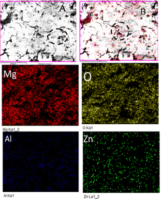 | ||
| Fig. 7 Microstructure of butyl amine functionalized graphene oxide coated Mg alloys after corrosion. | ||
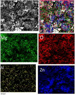
Fig. 8 shows the epoxy-coated Mg alloy microstructure after 5 days of immersion in the corrosion medium. The aggressive ions attack, highly affecting the alloy surface45–50 Several localized corrosion spots occur on the alloy surface. Furthermore, the heavy chloride electrolyte penetrating the coating surface severely affects the grain boundary.51,52 The elemental mapping results suggest that the oxygen concentration on the alloy surface increased due to the attack of corrosive ions. In the case of Al and Zn, significant losses were observed due to the corrosive medium and poor coating stability in the corrosive medium.
3.5 AFM studies
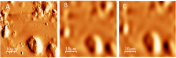
The AFM image of the epoxy-coated alloy shows surface roughness (Fig. 9). The coating surface has a pit formed due to the corrosive ions penetrating the coating surface. Fig. 9A presents the formation of pits on the coated Mg alloys, and significant pitting corrosion was observed on the alloy surface.53,54 In Fig. 9B and C, the pit size is increased by the corrosive ions penetrating through the epoxy coating. Furthermore, we monitored the alloy roughness in different ways. The roughness of the 15 μm alloy surface is shown in Fig. 10A–C. Furthermore, butyl amine functionalized GO coating on the Mg alloy shows a smooth surface, and there is no pitting corrosion on the alloy surface due to the butylamine functionalized GO.Pitting corrosion was initiated but could not develop continuously due to the strong adsorption of the protective layer on the alloy surface.55Fig. 10B and C show the average pit size on the Mg alloys. Thus, the butyl amine functionalized GO sheets may improve corrosion resistance.
3.6 Adsorption studies
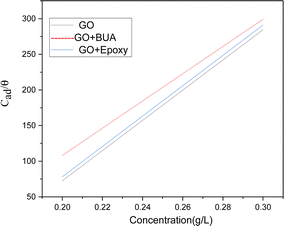
We have studied adsorption on Mg alloys at room temperature and under different concentrations. Fig. 11 shows a plot of surface coverage θ vs. concentration of inhibitor molecules. With the increase of the concentration of inhibitor molecules, absorption is increased. Butyl amine functionalized GO exhibits physisorption and chemisorption, confirmed by the Langmuir adsorption principles.56,57 The Langmuir adsorption study reveals that negatively charged inhibitor molecules interact with positive charges on the metal surface by electrostatic interactions.3.7 Computational studies
In Fig. 12, the butyl amine functionalized GO model structures optimized with the implicit effects of water taken into account are provided for the neutral (Fig. 12A) and protonated (Fig. 12B) species, along with the calculated NBO charges for selected atoms. Because only one layer of GO was used in the model, it became distorted upon optimization, as expected. As can be seen, upon protonation on the![[double bond, length as m-dash]](https://www.rsc.org/images/entities/char_e001.gif) N group, the C–N bond becomes elongated by ca. 0.02 Å, and the N–C(GO) bond distances become elongated more significantly by 0.06–0.08 Å. Also, the butyl amine moiety becomes noticeably less tilted upon protonation than the neutral species.
N group, the C–N bond becomes elongated by ca. 0.02 Å, and the N–C(GO) bond distances become elongated more significantly by 0.06–0.08 Å. Also, the butyl amine moiety becomes noticeably less tilted upon protonation than the neutral species.
The NBO analysis results show that upon protonation, the charges of the butyl amine moiety remain essentially the same, and only the charges on the carbons of GO, to which the N-atom is bound to increase slightly, by 0.03–0.04 e. In general, as can be seen from the NBO results, the butyl amine moiety atoms bear noticeable negative charges, −0.26 to −0.68 e, and thus, the butyl amine functionalized GO surface can act as a nucleophilic agent and interact with various oxidizers in solution.
In Fig. 13, four frontier orbitals of the butyl amine functionalized GO model are presented for the neutral (Fig. 13A) and protonated (Fig. 13B) structures: HOMO and HOMO−1, and LUMO and LUMO+1. An analysis of the MOs shows the following. (i) Mostly, GO, and the N-group of the butyl amine contribute to the frontier orbitals under consideration. (ii) The energy differences between the HOMO and HOMO−1 are quite small, ca. 0.3 eV; thus, participation of these orbitals in (electro)chemical processes should be considered as possible. (iii) The HOMO–LUMO gaps for the neutral and protonated systems are relatively small, ca. 0.106 and 0.097 a.u. or ca. 2.88 and 2.64 eV, respectively, displaying that the butyl amine functionalized GO should be quite reactive in the solution media. (iv) For the protonated structure, the computed MO energies were lower than the neutral structure due to extra stabilization of the cation MOs in the polar solvent.
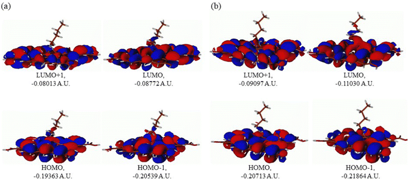 | ||
| Fig. 13 Molecular orbitals of the GO model functionalized with butyl amine: neutral (A) and protonated (B). Energies are given in a.u. | ||
Also, the HOMO–LUMO gap of the protonated structures was computed to be smaller by ca. 0.24 eV than the gap of the neutral structure, suggesting that, in general, the protonated species would be more reactive towards oxidants in solution.
The computed global hardness values of the two models are quite small, ca. 0.053–0.048 a.u. and global softness σ values are quite noticeable (Table 2). This suggests that neutral and protonated systems would be highly reactive towards oxidizing agents attacking the surface, with protonated structures being even more reactive than the neutral species. This is also supported by the relatively small HOMO–LUMO gap value (ΔE) (Table 2). The small calculated values of the global electronegativity (χ) and electrophilicity (ω) also suggest high potential reactivity of the butyl amine covalently functionalized GO towards oxidizing electrophilic agents.
| HOMO | LUMO | ΔE | I | A | χ | η | σ | ω | |
|---|---|---|---|---|---|---|---|---|---|
| A | −0.19363 | −0.08772 | 0.10591 | 0.19363 | 0.08772 | 0.140675 | 0.05296 | 18.8822 | 0.18683 |
| B | −0.20713 | −0.11030 | 0.09683 | 0.20713 | 0.1103 | 0.158715 | 0.04842 | 20.6526 | 0.26012 |
Furthermore, the high potential reactivity of the butylamine covalently functionalized GO supported by the plots of the molecular electrostatic potential (MEP), as shown in Fig. 14. As can be seen in Fig. 14A, for the neutral species, a significant accumulation of the negative potential (shown by red color) occurs on the ![[double bond, length as m-dash]](https://www.rsc.org/images/entities/char_e001.gif) O group close to the butylamine group and the part of the butylamine group is close to this
O group close to the butylamine group and the part of the butylamine group is close to this ![[double bond, length as m-dash]](https://www.rsc.org/images/entities/char_e001.gif) O group, implying that they act as nucleophilic agents and react with various oxidizers in solution. On the other hand, in the protonated structure (Fig. 14B), a significant accumulation of the positive potential (shown by blue) is observed at the amine moiety and on the carbon atoms of the GO layer close to it, making them able to interact with chloride ions from the solution.
O group, implying that they act as nucleophilic agents and react with various oxidizers in solution. On the other hand, in the protonated structure (Fig. 14B), a significant accumulation of the positive potential (shown by blue) is observed at the amine moiety and on the carbon atoms of the GO layer close to it, making them able to interact with chloride ions from the solution.
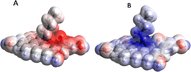 | ||
| Fig. 14 Molecular electrostatic potential (MEP) plots of the GO model functionalized with butyl amine: neutral (A) and protonated (B). | ||
4. Conclusions
• Butylamine functionalized graphene oxide (GO) was first synthesized, and its structural features, corrosion inhibition, and electrochemical properties were thoroughly characterized using various approaches.• The spectroscopy studies confirmed the chemical modification of the GO sheets by butylamine due to the presence of respective functional groups. The Raman spectroscopy results suggest that the sp2 carbon vibrations and carbon disorder vibrations for the modified GO differed from those for the pristine GO sheet.
• The microscopy studies illustrate a few micron thicknesses of GO sheets. The electrochemical studies show superior corrosion inhibition efficiency of the butylamine functionalized GO sheets compared to that of the epoxy coating for magnesium alloys.
• The DFT studies completely support the experimental investigation results and suggest the high potential reactivity of the butylamine covalently functionalized GO towards oxidizing electrophilic agents and chloride ions present in the corrosive solutions.
Conflicts of interest
There are no conflicts to declare.Acknowledgements
N. P. is thankful to the Non-NET fellowship and central university of Gujarat CIF facilities. The author would also like to thank the UGC NRC Central University of Hyderabad, School of Chemistry, for supporting this research work. A. K. acknowledges the financial support from UTFSM and the computational facilities of the Department of Chemistry, ITA, Brazil.Notes and references
- H. M. A. E. Lateef and A. H. Tantawy, RSC Adv., 2016, 6, 8681–8700 RSC.
- E. Koh, S. Y. Baek, N. K. Kim, S. Lee, J. Shin and Y. W. Kim, New J. Chem., 2014, 38, 4409–4419 RSC.
- S. M. Shaban, RSC Adv., 2016, 6, 39784–39800 RSC.
- D. Payra, M. Naito, Y. Fujii, N. L. Yamada, S. Hiromotoe and A. Singh, RSC Adv., 2015, 5, 15977–15984 RSC.
- J. Bartley, N. Huynh, S. E. Bottle, H. Flitt, T. Notoya and D. P. Schweinsberg, Corros. Sci., 2003, 45, 81–96 CrossRef.
- B. Vaghefinazari, C. Wang, D. Mercier, D. Mei, A. Seyeux, P. Marcus, C. Blawert, S. V. Lamaka and M. L. Zheludkevich, Corros. Sci., 2021, 192, 109830 CrossRef CAS.
- Q. Zhang, L.-X. Gao, Q.-R. Cai and K. Y. Lee, Mater. Corros., 2010, 6(61), 16–21 CrossRef.
- Z. Yu, J. Chen, H. Yan, W. Xia, B. Su, X. Gong and H. Guo, Mater. Lett., 2020, 260, 126920 CrossRef CAS.
- S. T. Keera, Br. Corros. J., 2001, 36, 261–265 CrossRef CAS.
- Z. Cui, F. Ge, Y. Lin, L. Wang, L. Lei, H. Tian, M. Yu and X. Wang, Electrochim. Acta, 2018, 278, 421–437 CrossRef CAS.
- R. L. Liu, J. R. Scully, G. Williams and N. Birbilis, Electrochim. Acta, 2018, 260, 184–195 CrossRef CAS.
- G. Williams, H. A. Dafydd, H. N. McMurray and N. Birbilis, Electrochim. Acta, 2016, 219, 401–411 CrossRef CAS.
- C. Q. Li, D. K. Xu, X.-B. Chen, B. J. Wang, R. Z. Wu, E. H. Han and N. Birbilis, Electrochim. Acta, 2018, 260, 55–64 CrossRef CAS.
- J. Y. Chen, X. B. Chen, J. L. Li, B. Tang, N. Birbilis and X. Wang, J. Mater. Chem. A, 2014, 2, 5738–5743 RSC.
- N. Birbilis, A. D. King, S. Thomas, G. S. Frankel and J. R. Scully, Electrochim. Acta, 2014, 132, 277–283 CrossRef CAS.
- Y.-J. Wu, X.-B. Chen, G. Williams, J. R. Scully, T. Gengenbach and N. Birbilis, RSC Adv., 2016, 6, 43408–43417 RSC.
- G. Williams, N. Birbilis and H. N. McMurray, Faraday Discuss., 2015, 180, 313–330 RSC.
- P. Gore, S. Fajardo, N. Birbilis, G. S. Frankel and V. S. Raja, Electrochim. Acta, 2019, 293, 199–210 CrossRef CAS.
- W. R. Osório, E. S. Freitas and A. Garcia, Electrochim. Acta, 2013, 102, 436–445 CrossRef.
- M. J. Yoo and H. B. Park, Carbon, 2019, 141, 515–522 CrossRef CAS.
- W. R. Osório, L. C. Peixoto, D. J. Moutinho, L. G. Gomes, I. L. Ferreira and A. Garcia, Mater. Des., 2011, 32, 3832–3837 CrossRef.
- X. L. Zhang, Zh. H. Jiang, Zh. P. Yao, Y. Song and Zh. D. Wu, Corros. Sci., 2009, 51, 581–587 CrossRef CAS.
- E. McCafferty, Corros. Sci., 2005, 47, 3202–3215 CrossRef CAS.
- M. J. Frisch, G. W. Trucks, H. B. Schlegel, G. E. Scuseria, M. A. Robb, J. R. Cheeseman, G. Scalmani, V. Barone, G. A. Petersson, H. Nakatsuji, X. Li, M. Caricato, A. Marenich, J. Bloino, B. G. Janesko, R. Gomperts, B. Mennucci, H. P. Hratchian, J. V. Ortiz, A. F. Izmaylov, J. L. Sonnenberg, D. Williams-Young, F. Ding, F. Lipparini, F. Egidi, J. Goings, B. Peng, A. Petrone, T. Henderson, D. Ranasinghe, V. G. Zakrzewski, J. Gao, N. Rega, G. Zheng, W. Liang, M. Hada, M. Ehara, K. Toyota, R. Fukuda, J. Hasegawa, M. Ishida, T. Nakajima, Y. Honda, O. Kitao, H. Nakai, T. Vreven, K. Throssell, J. A. Montgomery Jr., J. E. Peralta, F. Ogliaro, M. Bearpark, J. J. Heyd, E. Brothers, K. N. Kudin, V. N. Staroverov, T. Keith, R. Kobayashi, J. Normand, K. Raghavachari, A. Rendell, J. C. Burant, S. S. Iyengar, J. Tomasi, M. Cossi, J. M. Millam, M. Klene, C. Adamo, R. Cammi, J. W. Ochterski, R. L. Martin, K. Morokuma, O. Farkas, J. B. Foresman and D. J. Fox, Gaussian 09, Revision B.01, Gaussian, Inc.; Wallingford CT, 2009 Search PubMed.
- R. Parr and W. G. Yang, Density-functional theory of atoms and molecules, Oxford University Press: Oxford, 1989 Search PubMed.
- A. McLean and D. G. S. Chandler, J. Chem. Phys., 1980, 72, 5639–5648 CrossRef CAS.
- E. Cances and B. T. Mennucci, J. Chem. Phys., 1997, 107, 3032–3041 CrossRef CAS.
- H. P. Mungse, R. Singh, H. Sugimura, N. Kumar and O. P. Khatri, Phys. Chem. Chem. Phys., 2015, 17, 20822–20829 RSC.
- S. P. Zhang and H. O. Song, New J. Chem., 2012, 36, 1733–1738 RSC.
- S. Kumari, O. P. Sharma and O. P. Khatr, Phys. Chem. Chem. Phys., 2016, 18, 22879–22888 RSC.
- J. Yang, Y. Wang, J. Wang and M. B. Chan-Park, RSC Adv., 2015, 5, 11124–11127 RSC.
- U. Baruah and D. Chowdhury, RSC Adv., 2016, 6, 67102–67112 RSC.
- C. Zhu, Y. Yan, F. Wang, J. Cui, S. Zhao, A. Gao and G. Zhang, RSC Adv., 2019, 9, 7324–7333 RSC.
- C. C. Caliman, A. F. Mesquita, D. F. Cipriano, J. C. C. Freitas, A. A. C. Cotta, W. A. A. Macedo and A. O. Porto, RSC Adv., 2018, 8, 6136 RSC.
- A. Frignani, V. Grassi, F. Zanotto and F. Zucchi, Corros. Sci., 2012, 63, 29–39 CrossRef CAS.
- S. Palussière, J. Cure, A. Nicollet, P. Fau, K. Fajerwerg, M. L. Kahn, A. Estève and C. Rossi, Phys. Chem. Chem. Phys., 2019, 21, 16180–16189 RSC.
- C. C. Caliman, A. F. Mesquita, D. F. Cipriano, J. C. C. Freitas, A. A. C. Cotta, W. A. A. Macedo and A. O. Porto, RSC Adv., 2018, 8, 6136–6145 RSC.
- B. Vaghefinazari, C. Wang, D. Mercier, D. Mei, A. Seyeux, P. Marcus, C. Blawert, S. V. Lamaka and M. L. Zheludkevich, Corros. Sci., 2021, 192, 109830 CrossRef CAS.
- L. Prince, M.-A. Rousseau, X. Noirfalise, L. Dangreau, L. B. Coelho and M.-G. Olivier, Corros. Sci., 2021, 179, 109131 CrossRef CAS.
- L. M. Calado, M. G. Taryba, Y. Morozov, M. J. Carmezim and M. Fátima Montemor, Corros. Sci., 2020, 170, 108648 CrossRef CAS.
- J. Hu, D. Zeng, Z. Zhang, T. Shi, G.-L. Song and X. Guo, Corros. Sci., 2013, 74, 35–43 CrossRef CAS.
- H. Bai, Y. Xu, L. Zhao, C. Li and G. Shi, Chem. Commun., 2009, 1667–1669 RSC.
- A. Muzyka, J. Sun, T. H. Fereja, Y. Lan, W. Zhang and G. Xu, Anal. Methods, 2019, 11, 397–414 RSC.
- Y. H. Wen, L. Shao, P. C. Zhao, B. Y. Wang, G. P. Cao and Y. S. Yang, J. Mater. Chem. A, 2017, 5, 15752–15758 RSC.
- T. Ishizaki, S. Chiba, K. Watanabe and H. Suzuki, J. Mater. Chem. A, 2013, 1, 8968–8977 RSC.
- H. Wei, D. Ding, S. Wei and Z. Guo, J. Mater. Chem. A, 2013, 1, 10805–10813 RSC.
- C. Ding, Y. Liu, M. D. Wang, T. Wang and J. Fu, J. Mater. Chem. A, 2016, 4, 8041–8052 RSC.
- W. Sun, L. Wang, T. Wu, Y. Pana and G. Liu, J. Mater. Chem. A, 2015, 3, 16843–16848 RSC.
- S. Dea and J. L. Lutkenhaus, Green Chem., 2018, 20, 506–514 RSC.
- H. Qian, D. Xu, C. Du, D. Zhang, X. Li, L. Huang, L. Deng, Y. Tu, J. M. C. Molc and H. A. Terryn, J. Mater. Chem. A, 2017, 5, 2355–2364 RSC.
- R. C. Zeng, Z. G. Liu, F. Zhang, S. Q. Li, H. Z. Cui and E. H. Han, J. Mater. Chem. A, 2014, 2, 13049–13057 RSC.
- M. J. Nine, M. A. Cole, D. N. H. Tran and D. Losic, J. Mater. Chem. A, 2015, 3, 12580–12602 RSC.
- J. Ding, H. Zhao, D. Ji, B. Xu, X. Zhao, Z. Wang, D. Wang, Q. Zhou and H. Yu, J. Mater. Chem. A, 2019, 7, 2864–2874 RSC.
- X. Li, P. Bandyopadhyay, T. Kshetri, N. H. Kim and J. H. Lee, J. Mater. Chem. A, 2018, 6, 21501–21515 RSC.
- R. L. Liu, M. F. Hurley, A. Kvryan, G. Williams, J. R. Scully and N. Birbilis, Sci. Rep., 2016, 6, 28747 CrossRef CAS PubMed.
- H. Su, Y. Wu, Y. Zhang, Y. Jiang, Y. Ding, L. Wang and J. Zhang, Corros. Sci., 2021, 178, 109010 CrossRef CAS.
- Z. Li, W. Yang, Q. Yu, Y. Wu, D. Wang, J. Liang and F. Zhou, Langmuir, 2019, 35(5), 1134–1145 CrossRef CAS PubMed.
| This journal is © The Royal Society of Chemistry 2023 |

