 Open Access Article
Investigation of the cycling stability and energy storage properties of zinc titanate (ZnTiO3) perovskite material for zinc–air batteries†
Upasana
Bhardwaj
,
Aditi
Sharma
and
H. S.
Kushwaha
 *
*
Materials Research Centre, Malaviya National Institute of Technology, Jaipur, Rajasthan 302017, India. E-mail: himmatsingh.mrc@mnit.ac.in
First published on 11th August 2023
Abstract
With the merits of advantageous structure, morphology, purity, composition, and porosity, perovskites are explored as bifunctional alternatives to replace precious metals in the application of zinc–air batteries (ZABs). In this work, a new perovskite material, ZnTiO3 (Zinc Titanate; ZTO), was developed and investigated for its performance in a rechargeable zinc–air battery (ZAB). The oxygen activities were also examined in alkaline solutions with O2 and N2 purging on the RDE (rotating disc electrode) system. The zinc–air cell so developed exhibits good performance with a specific capacity of 625 mA h g−1 at a current density of 5 mA cm−2. The rechargeable ZTO battery also shows high cycling stability with minimum fluctuations at 5 mA cm−2 for 500 cycles, resulting in ZnTiO3 being a promising candidate for zinc–air batteries.
1. Introduction
In recent years, zinc–air technology has emerged as a propitious option in energy research focused on creating efficient, cheap and environment friendly models. Zinc–air batteries show enhanced storage capabilities with a theoretical energy density of 1353 W h kg−1 and volumetric energy density of 6136 W h L−1 with the open-circuit voltage (OCV) of 1.65 V.1–3 As the battery component involves a zinc electrode, the battery is low cost due to its abundance, low equivalent weight, environmental benignity, and safety.4–8 The zinc–air batteries are also capable of easy charging, minimum toxicity, no corrosion, and reduced possibility of thermal runaway.9,10The low catalytic activity of an air electrode during charge–discharge is hampered by the slow processes of oxygen evolution and reduction reactions (ORR–OER).11 These slow reactions cause large charge–discharge potential gaps, low round trip efficiency and poor power capabilities.12 The noble precious-metal-based electrocatalysts like platinum (Pt) for the ORR and Ir–/Rb–O2 for the OER have been investigated as the most efficient options for zinc–air batteries.5,13–15 But the high cost and scarcity of these precious metals limit their practical usage in the energy market. Therefore, a lot of research has been carried out in recent years to investigate and synthesize an efficient, low-cost bi-functional electrocatalyst for ZABs. A lot of effort has been made in investigating non-precious bifunctional alternatives. Many metal oxides and perovskites have been explored, like MnO2, LaMnO3 and its composites, Sr2TiMnO6, CaCu3Ti4O12, etc., which are well known and comparable to the precious options.1,4,11,14 But in spite of the structural flexibility and enhanced oxygen reduction activities, they lack in providing better performances. Hence, it has become crucial to investigate and develop more non-precious electrocatalysts for zinc–air battery applications.
Perovskites (molecular formula – ABO3) benefitting from the arrangement of transition metals (e.g., Mn, Co, Ni) with rare-earth metals and oxygen have recently received a lot of attention as rich sources for the intentional design of effective, bifunctional and non-precious metal catalysts for zinc–air batteries.16 They have controllable functionalities, adsorption affinity, and a high surface area due to their open three-dimensional structure, making them a viable option. Also, because of their high catalytic activity, perovskites are highly durable for the OER in alkaline conditions.16,17 Perovskites show effectiveness in the fields of thermostable glasses (showing application in blue lasers),18 capacitors19,20 and other energy storage applications.21
Therefore, the novelty of this research is the first-ever introduction of a ZnTiO3 electrocatalyst synthesized using solid-state synthesis for zinc-air battery.22,23 ZTO is an efficient catalyst exhibiting excellent dielectric properties at low sintering temperatures.24 The electrochemical activity of the perovskite was tested to evaluate the ORR–OER activities using a RDE (rotating disk electrode) system in alkaline media. The zinc–air battery cell was also developed and assessed in ambient air conditions.
2. Experimental
2.1 Materials and synthesis
The ZnTiO3 perovskite was prepared using the solid-state synthesis route.19 The process was done by mixing the precursor compounds of ZnO purchased from Merck and TiO2 purchased from Central drug house (P) Ltd in the ratio of 1![[thin space (1/6-em)]](https://www.rsc.org/images/entities/char_2009.gif) :
:![[thin space (1/6-em)]](https://www.rsc.org/images/entities/char_2009.gif) 1 using a mortar–pestle. The mixture was calcined at the temperature of 900 °C at the rate of 10 °C min−1 for 30 hours to yield the zinc titanate electrocatalyst. The product retrieved was then powdered using the mortar–pestle for an hour.
1 using a mortar–pestle. The mixture was calcined at the temperature of 900 °C at the rate of 10 °C min−1 for 30 hours to yield the zinc titanate electrocatalyst. The product retrieved was then powdered using the mortar–pestle for an hour.
2.2 Material characterization
XRD (X-ray diffraction) was performed on a Rigaku SmartLab Diffractometer with Cu-K radiation (λ = 0.154 nm), 2θ = 10 to 80°, and a step size of 0.02 to analyse the crystal structure and purity of the perovskite sample. The XPS (X-ray photo-electron spectroscopy) data was collected using an Oxford Instruments Omicron (model ESCA+) ultra-high vacuum chamber connected to a 124 mm hemispherical electron analyzer and monochromatic Al-Kα radiation source. Brunauer–Emmett–Teller (BET) studies were performed on a Nova Touch Lx2 by quantachrome Instruments, USA to obtain nitrogen sorption isotherms in order to determine the specific surface area of the sample. The surface morphology and material distribution were determined using an Ei Nova Nano FESEM 450 (field emission scanning electron microscope).The electrochemical characterization was performed using an RDE system from Biologic instruments in connection with a PG-Lyte electrochemical workstation from Kanopy instruments on a three electrode system using an RDE made up of glassy carbon with the disc size of 3 mm. The counter and the reference electrode taken were platinum wire and Ag/AgCl in 3 M KCl, respectively.
2.3 Zinc–air battery fabrication
A regular zinc–air cell was designed and developed using a ZnTiO3 (ZTO) cathode and a zinc anode in 6 M KOH + 0.2 M Zn(Ac)2 electrolyte. The cathode was prepared using two different slurries coated creating an active and a hydrophobic site on the nickel foam of 1 cm2. A homogeneous ink was created by dissolving PVDF and Vulcan carbon (7![[thin space (1/6-em)]](https://www.rsc.org/images/entities/char_2009.gif) :
:![[thin space (1/6-em)]](https://www.rsc.org/images/entities/char_2009.gif) 3) in ethanol and coating one side of the foam. The electrode was then hot-pressed at 350 °C to create a hydrophobic site that would limit clogging and increase oxygen capacity. A slurry coating, on the other hand, was created by combining the catalyst and Vulcan carbon in a 1
3) in ethanol and coating one side of the foam. The electrode was then hot-pressed at 350 °C to create a hydrophobic site that would limit clogging and increase oxygen capacity. A slurry coating, on the other hand, was created by combining the catalyst and Vulcan carbon in a 1![[thin space (1/6-em)]](https://www.rsc.org/images/entities/char_2009.gif) :
:![[thin space (1/6-em)]](https://www.rsc.org/images/entities/char_2009.gif) 1 ratio with the addition of 5% (w/v) Nafion solution as a binder. After that, the solution was dispersed in isopropanol to form a homogeneous mixture. The coated electrode was then placed in a vacuum oven at 60 °C for 2 hours. Furthermore, the performance of the assembled battery cell was carried out on a Neware battery testing system (8 ports).
1 ratio with the addition of 5% (w/v) Nafion solution as a binder. After that, the solution was dispersed in isopropanol to form a homogeneous mixture. The coated electrode was then placed in a vacuum oven at 60 °C for 2 hours. Furthermore, the performance of the assembled battery cell was carried out on a Neware battery testing system (8 ports).
3. Results and discussion
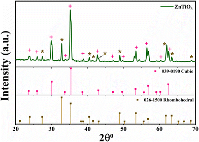
For the evaluation of the phase purity and crystal structure, the perovskite sample was characterized by X-ray diffraction (XRD), as shown in Fig. 1. The sample was found to be polycrystalline giving cubic as well as rhombohedral structures. The perovskite peak centered at almost 36° (311) shows a cubic structure, well matched with the standardized data (JCPDS No. 00-039-0190). There is an occurrence of some extra peaks attributed to the rhombohedral form of ZTO, confirmed with the JCPDS No. 00-026-1500. The average crystallite size of the as-prepared crystalline material was calculated to be 41.23 nm using the Scherrer equation:Fig. S1 (ESI†) shows a comparative X-ray diffraction pattern of ZTO, ZnO and TiO2 (see ESI†). To further confirm the elemental composition of the synthesized perovskite powder, XPS analysis was performed, as shown in Fig. 2.
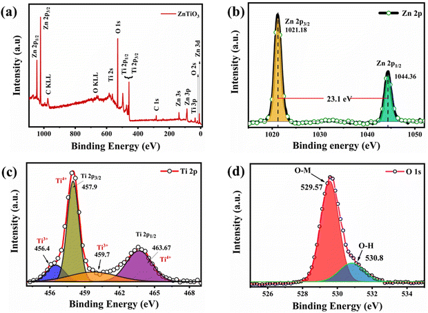
The XPS survey spectra for the perovskite sample ZnTiO3 taken in the range of 0–1100 eV binding energy (Fig. 2(a)) show no impurities. Peaks corresponding to the Zn (2p, 3s, 3p, 3d), Ti (2s, 2p, 3p) and O 1s are identified well in the spectra with the Auger peaks of carbon (C KLL) and oxygen (O KLL).25Fig. 2(b) depicts the high resolution scan of Zn, depicting peaks of Zn 2p1/2 and Zn 2p3/2 at the binding energies of 1044 and 1021 eV, respectively. Whereas, the Ti 2p scan is shown in Fig. 2(c) displaying de-convoluted peaks of Ti 2p1/2 and Ti 2p3/2 at 457.9 and 463.67, respectively. The spectra also show the presence of the Ti3+ state of Ti in ZTO confirming the oxygen deficiency on the exposed layer. Fig. 2(d) shows the O 1s spectra exhibiting de-convoluted peaks at the binding energies of 529.57 and 530.8 eV. This de-convolution confirms the occurrence of surface absorbed OH− and O2 binding and the presence of highly oxidative species, which confirms the O2 vacancies on the surface, as given by (O2−/O−), which is very advantageous for the ORR process as it helps to bind absorbed oxygen.13,26
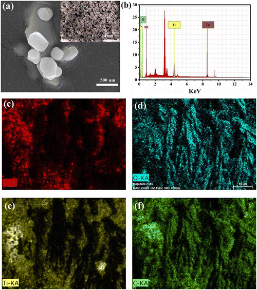
Fig. 3(a) shows an SEM image of the as-synthesized perovskite catalyst to understand the morphology and structure. Homogenous structures were found as shown in the image. Fig. 3(b) presents the EDS spectra of the sample confirming the elemental composition. The data confirms the presence of titanium (Ti) in a good quantity, i.e. almost 41%, which is responsible for binding oxygen forming an M–O bond. To see the dispersion of the slurry on the electrode, EDS mapping was also performed confirming a good dispersion of each element, as shown in Fig. 3(c–f).
To confirm the surface of the sample, high resolution transmission electron microscopy (HR-TEM) images were further analyzed, as shown in Fig. 4(a). Due to the interconnected structure seen in the TEM image, it was seen that the grains in the image were agglomerated. HR-TEM was also used to calculate the interplanar spacing (d) of the perovskite material, as shown in Fig. 4(b). The obtained micrograph shows well-defined crystalline fringes with a d-spacing of 0.3 nm. To acquire the planes, the selected area electron diffraction (SAED) technique was carried out at one of the edges of the sample with no agglomeration regions. SAED (as shown in Fig. 4(c)) comprises several lattice points corresponding to the planes matching well with the XRD obtained.
For the enhanced oxygen interaction, a highly porous material with high surface area is required. Hence, to confirm the porosity and surface area of the perovskite powder, a BET test was performed, as shown in Fig. 5. Fig. 5(a) shows the N2 adsorption–desorption isotherm confirming the pore radius (dV(r)) to be ∼1 nm with the type IV isotherm indicating a mesoporous structure. Fig. 5(b) shows the multi-point graph of ZnTiO3 giving the surface area of the sample 2.9 m2 g−1. The size distribution curve (Fig. 5(c)) operates on the non-ideality pressure of 6.58 × 10⁻⁵ torr−1 and bath temperature of 77.5 K showing the pore size of 1–30 nm confirming the mesopore formation of ZnTiO3 perovskite.
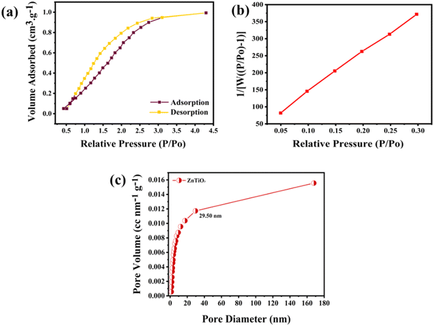 | ||
| Fig. 5 (a) BET adsorption–desorption isotherms of the perovskite sample; (b) multi-point graph of ZnTiO3; (c) size distribution curve of ZnTiO3 perovskite. | ||
3.1 Electrochemical characterization
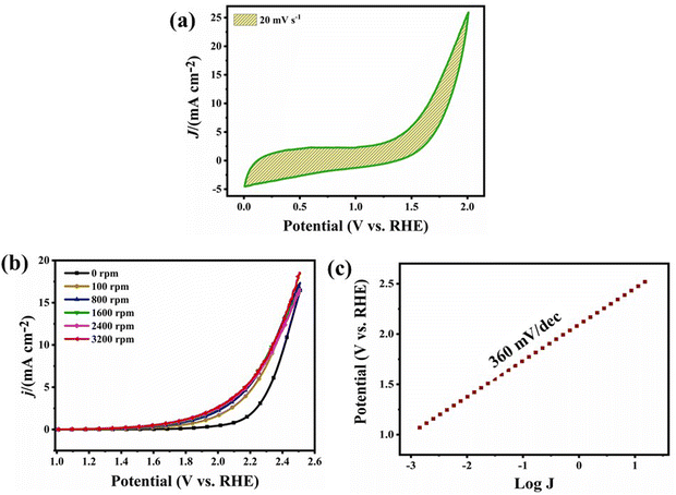
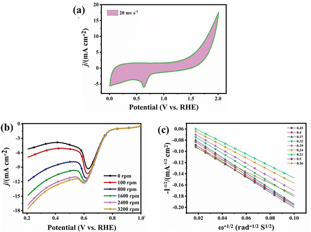
The metal–air battery chemistry is primarily based on the interaction of the atmospheric oxygen with the bi-functional catalyst and its redox reactions.13 The ORR - OER (oxygen reduction - evolution reaction) were performed on a rotating disk electrode with the disk diameter of 3 mm. LSV (linear sweep voltammetry) was recorded to analyse the barrier, i.e. the over-potential for oxygen evolution. The tests for the OER were performed in N2 purged, 1 M KOH solution. Fig. 6(a) shows the cyclic voltammetry ranging between the potential window of 0–2.0 V at a scan rate of 20 mV s−1. The cyclic plot shows no reduction peak following the process of evolution. Fig. 6(b) shows the LSV curves taken at different rotation speeds from 0–3200 rpm giving the potential of 2.2 V at the current density of 10 mA cm−2. The overpotential (Fig. 6(c)) was calculated to be 360 mV dec−1 using the Tafel plot (log![[thin space (1/6-em)]](https://www.rsc.org/images/entities/char_2009.gif) J vs. potential (V vs. RHE)).
J vs. potential (V vs. RHE)).
Since the catalyst with a four electron pathway is most preferred for the development of a zinc–air battery in alkaline medium, all the tests for the ORR were performed in O2 purged, 0.1 M KOH solution giving a cyclic voltammogram at a current scan of 20 mV s−1 and in the potential range of 0–2 V vs. RHE, as shown in Fig. 7(a). The graph shows a reduction peak at the potential of 0.65 V. To attain the diffusion controlled region and to find the number of electrons transferred, linear sweep voltammetry (LSV) was also performed at different scan rates from 0–3200 rpm in the potential window of 1–0.2 V, as shown in Fig. 7(b). The result shows the onset potential (E0) of 0.78 V with the E1/2 of 0.68 V giving the maximum current density of 18 mA cm−2. Fig. 7(c) shows the K–L plot confirming the no. of transferred electrons to be 4 using the Koutecky–Levich equation.
3.2 Battery characterization
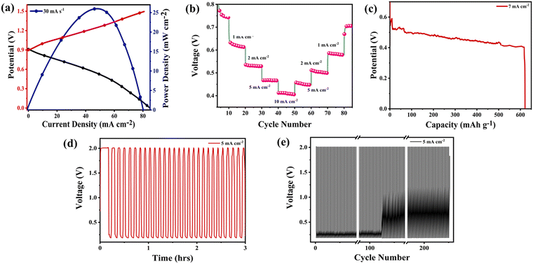
A regular zinc–air cell was designed and developed using a nickel foam coated ZTO cathode and a zinc anode in 6 M KOH + 0.2 M Zn(Ac)2 electrolyte. CV of the assembled cell was taken at various scan rates ranging from 1–100 mV s−1, as shown in Fig. S2 (ESI†). It can be seen that the CV curve shows no difference with an increase in scan rate. A little distortion in the shape of the curve is observed due to the relatively large IR drop (internal resistance) as well as the inclusive ion/electron pathway, which causes a sluggish diffusion process.27–29 To check the peak potential and to find the power density of the developed cell, a galvanostatic charge–discharge test was performed, as shown in Fig. 8(a). The figure shows that the maximum power density attained by the battery came out to be 25 mW cm−2 at a current density of 47 mA cm−2. The battery was tested at different scan rates, as shown in Fig. 8(b).The galvanostatic discharge curves showed that with an increase in current density, the plateaux of the discharge potentials decreased. The ZTO catalyst battery demonstrated a voltage plateaux of 0.62, 0.56, 0.46 and 0.4 V at discharge current densities of 1, 2, 5 and 10 mA cm−2, respectively. Furthermore, the battery shows a specific capacity of 625 mA h g−1 at the current density of 7 mA cm−2 at a discharge rate of 0.04 A, as shown in Fig. 8(c). The battery shows the occurrence of a flat discharge potential at around 0.4 V giving the energy density of 250 W h kg−1. To check the battery's stability and cyclabilities, a galvanodynamic charge–discharge test was performed for 230 cycles for hours. Fig. 8(d) clearly shows that the battery performance was stable for hours in the potential range of 0.2–2 V. The potential gap achieved was 1.8 V at a fixed current density of 5 mA cm−2. The battery also shows an outstanding retention capacity of 91%, which fairly depicts the good performance of the ZTO battery (Fig. S4, ESI†). Fig. 8(e) shows the cycle numbers vs. potential (V), indicating an overall stable battery performance. The result offers good stability with minimum to no fluctuations.
4. Conclusions
In summary, ZnTiO3 was synthesized using a solid-state route to determine and evaluate the performance of zinc–air batteries. The potential difference (ΔE) was calculated to be 1.65 V, indicating the activity of the ZAB. The developed battery was tested under alkaline conditions in an ambient environment. The specific capacity calculated was 625 mA h g−1 at a current density of 7 mA cm−2 at a discharge rate of 0.04 A. The power density was also obtained to be 25 mW cm−2. The zinc–air cell exhibited excellent cycling stability for 226 charge–discharge cycles. Hence, ZnTiO3 can be regarded as an effective catalyst for zinc–air batteries.Conflicts of interest
On behalf of all authors, the corresponding author states that there is no conflict of interest.Acknowledgements
The authors are grateful to the WTI and DST for providing funding under the Water Technology Initiative Programme Project No. (EWFH/2019/222) and the DST-Inspire faculty scheme.References
- U. Bhardwaj, A. Sharma, A. Mathur, A. Halder and H. S. Kushwaha, Energy Storage, 2021, 4, 1–13 Search PubMed.
- H. Lee, O. Gwon, C. Lim, J. Kim, O. Galindev and G. Kim, ChemElectroChem, 2019, 6, 3154–3159 CrossRef CAS.
- J. Meng, F. Liu, Z. Yan, F. Cheng, F. Li and J. Chen, Inorg. Chem. Front., 2018, 5, 2167–2173 RSC.
- U. Bhardwaj, A. Sharma, A. Mathur, A. Halder and H. S. Kushwaha, Electrochem. Sci. Adv., 2021, 2, 1–15 Search PubMed.
- Y. Wang, J. Fu, Y. Zhang, M. Li, F. M. Hassan, G. Li and Z. Chen, Nanoscale, 2017, 9, 15865–15872 RSC.
- H. F. Wang, C. Tang, B. Wang, B. Q. Li, X. Cui and Q. Zhang, Energy Storage Mater., 2018, 15, 124–130 CrossRef.
- X. Zhang, R. Liu, Y. Zang, G. Liu, S. Liu, G. Wang, Y. Zhang, H. Zhang and H. Zhao, Inorg. Chem. Front., 2016, 3, 910–918 RSC.
- Y. Bu, O. Gwon, G. Nam, H. Jang, S. Kim, Q. Zhong, J. Cho and G. Kim, ACS Nano, 2017, 11, 11594–11601 CrossRef CAS PubMed.
- T. Warang, N. Patel, R. Fernandes, N. Bazzanella and A. Miotello, Appl. Catal., B, 2013, 132–133, 204–211 CrossRef CAS.
- A. R. Mainar, O. Leonet, M. Bengoechea, I. Boyano, I. De Meatza, A. Kvasha, A. Guerfi and J. A. Blázquez, Int. J. Energy Res., 2016, 40, 1032–1049 CrossRef CAS.
- A. R. Mainar, L. C. Colmenares, O. Leonet, F. Alcaide, J. J. Iruin, S. Weinberger, V. Hacker, E. Iruin, I. Urdanpilleta and J. A. Blazquez, Electrochim. Acta, 2016, 217, 80–91 CrossRef CAS.
- K. N. Jung, S. M. Hwang, M. S. Park, K. J. Kim, J. G. Kim, S. X. Dou, J. H. Kim and J. W. Lee, Sci. Rep., 2015, 5, 1–10 CrossRef.
- U. Bhardwaj, A. Sharma and H. S. Kushwaha, Sci. Rep., 2021, 12, 3999–4008 CrossRef PubMed.
- Z. Deng, Q. Yi, G. Li, Y. Chen, X. Yang and H. Nie, Electrochim. Acta, 2018, 279, 1–9 CrossRef CAS.
- J. Hu, L. Wang, L. Shi and H. Huang, Electrochim. Acta, 2015, 161, 115–123 CrossRef CAS.
- X. Yang, X. Wu, Z. Guo, Q. Li, H. Wang, C. Ke, W. Zeng, X. Qiu, Y. He, X. Liang and Y. Kim, RSC Adv., 2020, 10, 33327–33333 RSC.
- K. Elumeeva, J. Masa, J. Sierau, F. Tietz, M. Muhler and W. Schuhmann, Electrochim. Acta, 2016, 208, 25–32 CrossRef CAS.
- M. Jin, S. Huang, C. Quan, X. Liang, J. Du, Z. Liu, Z. Zhang and W. Xiang, J. Eur. Ceram. Soc., 2021, 41, 1579–1585 CrossRef CAS.
- L. Zhang, L. X. Pang, W. B. Li and D. Zhou, J. Eur. Ceram. Soc., 2020, 40, 3343–3347 CrossRef CAS.
- A. Mishra, B. Majumdar and R. Ranjan, J. Eur. Ceram. Soc., 2017, 37, 2379–2384 CrossRef CAS.
- H. Sun, X. Wang, Q. Sun, X. Zhang, Z. Ma, M. Guo, B. Sun, X. Zhu, Q. Liu and X. Lou, J. Eur. Ceram. Soc., 2020, 40, 2929–2935 CrossRef CAS.
- Y. S. Chang, Y. H. Chang, I. G. Chen and G. J. Chen, Solid State Commun., 2003, 128, 203–208 CrossRef CAS.
- Y. S. Chang, Y. H. Chang, I. G. Chen, G. J. Chen, Y. L. Chai, T. H. Fang and S. Wu, Ceram. Int., 2004, 30, 2183–2189 CrossRef CAS.
- A. Chaouchi, S. Marinel, M. Aliouat and S. d’Astorg, J. Eur. Ceram. Soc., 2007, 27, 2561–2566 CrossRef CAS.
- A. R. Phani, M. Passacantando and S. Santucci, J. Phys. Chem. Solids, 2007, 68, 317–323 CrossRef CAS.
- H. S. Kushwaha, N. A. Madhar, B. Ilahi, P. Thomas, A. Halder and R. Vaish, Sci. Rep., 2016, 6, 1–10 CrossRef PubMed.
- P. Chang, H. Mei, Y. Tan, Y. Zhao, W. Huang and L. Cheng, J. Mater. Chem. A, 2020, 8, 13646–13658 RSC.
- P. Chang, H. Mei, M. Zhang, Y. Zhao, X. Wang, L. Cheng and L. Zhang, Small, 2021, 17, 1–12 Search PubMed.
- P. Chang, H. Mei, Y. Zhao, W. Huang, S. Zhou and L. Cheng, Adv. Funct. Mater., 2019, 29, 1–13 Search PubMed.
Footnote |
| † Electronic supplementary information (ESI) available. See DOI: https://doi.org/10.1039/d3ma00183k |
| This journal is © The Royal Society of Chemistry 2023 |


