 Open Access Article
Confined oriented growth of FeSe2 on a porous graphene film as a binder-free anode for high-rate lithium-ion batteries†
Xiaoting
Zhang
 a,
Jiaxiu
Diao
a,
Jinghao
Qiao
a,
Yuhui
Wen
a,
Hongkun
Zhang
a,
Jiaxiu
Diao
a,
Jinghao
Qiao
a,
Yuhui
Wen
a,
Hongkun
Zhang
 *bc and
Rui
Wang
*a
aBeijing Key Laboratory of Clothing Materials R & D and Assessment, Beijing Engineering Research Center of Textile Nanofiber, School of Materials Design & Engineering, Beijing Institute of Fashion Technology, Beijing 100029, China. E-mail: clywangrui@bift.edu.cn
bGRINM Group Corporation Limited, Beijing 100088, China. E-mail: zhk@cutc.net
cChina United Test & Certification Co., Ltd, Beijing 101407, China
First published on 10th August 2023
Abstract
FeSe2 nanorod@porous graphene films (FeSe2@PG) were prepared by simple vacuum filtration, annealing, and subsequent selenylation. These FeSe2 nanorods were formed via confined oriented growth of FeSe2 nanoparticles. The morphology of FeSe2@PG was characterized using scanning electron microscopy (SEM) and transmission electron microscopy (TEM). The interfacial interaction between FeSe2 and graphene was investigated using X-ray photoelectron spectroscopy (XPS) and Raman spectroscopy. When used as an anode in lithium-ion batteries, the FeSe2@PG electrode exhibited an initial reversible capacity of 858 mA h g−1, which was increased to 1053 mA h g−1 after 50 cycles at 100 mA g−1. At high rates of 1, 2, 5, and 10 A g−1, the electrode maintained specific capacities of 483, 313, 265, and 178 mA h g−1, respectively, even after 1000 cycles. The excellent electrochemical performance of the FeSe2@PG electrode is attributed to the special structure of FeSe2@PG and the strong covalent bonds between graphene and FeSe2. Moreover, graphene can not only act as a substrate for the growth of FeSe2 nanorods, but also improve the conductivity of FeSe2. Furthermore, the porous structure of graphene can reduce the diffusion path of lithium ions and improve the penetration of the electrolyte into the graphene layer. In addition, a new covalent bond of C–Se–Fe was formed between graphene and FeSe2, which was beneficial for maintaining its structural stability.
Introduction
Energy crisis and environmental degradation have become two major problems in the world.1 Thus, the goal of carbon neutrality has been proposed. The development of clean renewable energy is one of the effective strategies for solving the above problems. Rechargeable lithium-ion batteries (LIBs) have become an important means for energy storage owing to their high capacity, high energy density, high operating voltage, and suitable working temperature.2–4 However, graphite, a mainstream commercial anode material, can hardly meet the increasing requirements of various energy storage devices such as electric vehicles and consumer electronics because of its low theoretical specific capacity (372 mA h g−1).5 Transition-metal chalcogenides are considered outstanding anode candidates owing to their high theoretical specific capacity, low cost, and environmental friendliness.6–8 Compared with transition-metal oxides and sulfides, metal selenides (MSe) exhibit superior electrical conductivity and higher stack density.9,10 Among them, FeSe2 is considered a promising anode material for LIBs owing to its high theoretical capacity, low toxicity, and good chemical stability.11,12 However, similar to other chalcogenide compounds, MSe also face the issue of serious volume expansion during charging and discharging. Pulverization of electrode materials may occur and even separate from the current collector, resulting in rapid capacity attenuation and deterioration of cycle performance.13 Moreover, although the conductivity of FeSe2 is better than those of metal oxides and sulfides, it still does not meet the requirements for application in LIBs. To improve its electrochemical performance, a commonly used method is the preparation of nanocarbon-based selenide metal composites.14Graphene, a two-dimensional carbon nanomaterial, has been considered an ideal material owing to its superior electronic conductivity and chemical stability.15,16 However, because of the planar structure of graphene, the ionic steric effect blocks the fast transmission of lithium ions in high-power batteries, thereby affecting the electrochemical properties of graphene-based electrode materials.17 Porous graphene not only improves the conductivity of FeSe2, but also avoids the blockage of the lithium-ion transmission path caused by the ionic steric effect due to its special porous structure. This is beneficial for decreasing the polarization, reducing the diffusion distance of lithium ions, and promoting the infiltration of the electrolyte on MSe, thus improving the electrochemical performance.18,19 For example, Rui et al. synthesized rod-like FeSe2-C wrapped with reduced graphene, which exhibited excellent performance as an anode material for LIBs.20 Qian et al. reported FeSe2/carbon matrix nanoparticles embedded into N-doped graphene sheets, which exhibited superior Li storage performance.21 Xiong et al. prepared FeSe2@reduced graphene oxide composites via a facile one-step hydrothermal technique, which showed superior specific capacity and good cycling stability.22 However, the majority of reported materials are in a powder form, and electrodes are often prepared through the slurry-coating method in a current collector using conducting additives and insulating binders. These additives and binders increase the cost and decrease the energy density of batteries without any capacity contribution.23,24 Thus, designing free-standing anode materials without conducting agents and binders is considerably important. In addition, the interfacial binding mechanism of FeSe2 with graphene must be elucidated.
Herein, we report the confined oriented growth of FeSe2 nanorods from nanoparticles on a porous graphene film via vacuum filtration, annealing, and subsequent selenylation to prepare a free-standing anode material without binders. Moreover, graphene is used as a highly conductive substrate to effectively connect with FeSe2. Furthermore, its porous structure provides abundant open channels for lithium-ion transport, shortens the diffusion distance of lithium ions, and increases the infiltration of the electrolyte. The FeSe2 nanorods are embedded in the pores of graphene films and selenium bridges are formed between FeSe2 and porous graphene. FeSe2@PG exhibits high specific capacity, superior rate performance, and stable cyclability when used as an anode material for LIBs. The excellent electrochemical performance of the electrode material is attributed to the highly conductive network formed by the graphene film and the tight covalent bonds between FeSe2 and graphene.
Experimental
Synthesis of FeSe2@PG
FeSe2@PG was prepared via facile vacuum filtration, annealing, and subsequent selenylation. Fe3C@PG was synthesized by mixing ferric nitrate and graphene oxide (fabricated using a modified Hummers' method using natural graphite25), filtration and followed by annealing at 1000 °C for 1 h in an argon gas atmosphere, as described in our previous work.26 Finally, the Fe3C@PG film and Se powders (0.6 g) were loaded into a quartz boat and placed in a tube furnace. FeSe2@PG was obtained after annealing at 400 °C for 8 h in a H2 (15%)/Ar (85%) atmosphere. To investigate the formation process of FeSe2@PG, selenization was performed for 4 and 6 h; the obtained samples were labeled as FeSe2@PG-4 and FeSe2@PG-6, respectively.Characterization
The morphology and structure of the obtained samples were investigated using scanning electron microscopy (SEM, JEOL JSM-7500F), transmission electron microscopy (TEM, JEOL JEM-2100F), and X-ray diffraction (XRD, Rigaku D/max-2500B2+/PCX) using Cu Kα radiation (λ = 1.5406 Å) over the range of 5–90° (2θ) at room temperature. X-ray photoelectron energy spectra (XPS) were recorded using monochromatized Al Kα radiation (1486.6 eV) with a 30 eV pass energy in 0.5 eV step over an area of 0.65 mm × 0.65 mm. The Raman spectra (WITec alpha 300) were investigated from 1000 to 2000 cm−1 at room temperature with an excitation line of 532 nm. The contents of FeSe2 in FeSe2@PG were investigated using thermogravimetry (TG) measurements. The samples were heated from room temperature to 700 °C at 5 °C min−1 under an O2 atmosphere.Electrochemical measurements
Lithium-ion storage performance was characterized using 2032 coin-type cells. The FeSe2@PG films were directly used as the working electrodes without any conductive additives and binders. A pure lithium sheet was used as the counter electrode, polypropylene served as the separator, and a solution of 1 M LiPF6 in ethylene carbonate (EC)–diethyl carbonate (DEC) (1![[thin space (1/6-em)]](https://www.rsc.org/images/entities/char_2009.gif) :
:![[thin space (1/6-em)]](https://www.rsc.org/images/entities/char_2009.gif) 1 by volume) was used as the electrolyte. The electrochemical performance was tested in a voltage window of 0.01–3.0 V using a Land battery test system (CT3001A, WUHAN LAND). Electrochemical impedance spectroscopy (EIS) was performed on a CHI600E electrochemical working station (Shanghai Chenhua). The frequency range for the EIS measurements was from 105 Hz to 10−2 Hz.
1 by volume) was used as the electrolyte. The electrochemical performance was tested in a voltage window of 0.01–3.0 V using a Land battery test system (CT3001A, WUHAN LAND). Electrochemical impedance spectroscopy (EIS) was performed on a CHI600E electrochemical working station (Shanghai Chenhua). The frequency range for the EIS measurements was from 105 Hz to 10−2 Hz.
Results and discussion
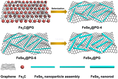
Fig. 1 illustrates the preparation process of FeSe2@PG-4, FeSe2@PG-6, and FeSe2@PG. First, the Fe3C@PG film was prepared via vacuum filtration and carbonization using graphene oxide and ferric nitrate as raw materials. Subsequently, the Fe3C@PG film was converted to FeSe2@PG-4, FeSe2@PG-6, and FeSe2@PG via selenization using Se powder at 400 °C for 4, 6, and 8 h, respectively. Fig. 2a shows FeSe2 nanorods uniformly anchored on the surface of the graphene film. The crystalline lattice of FeSe2 nanorods can be clearly observed in Fig. 2b, which is ca. 3.05 Å and corresponds to the (011) lattice plane of FeSe2. The selected area electron diffraction (SAED) image of FeSe2@PG shows diffraction spots matching (101), (030), and (101) diffraction rings, revealing that FeSe2 nanorods are polycrystalline. The EDS mapping shows that the nanorods contain Fe and Se elements, which are uniformly distributed throughout the nanorod (Fig. 2c and d).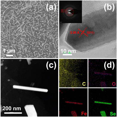 | ||
| Fig. 2 (a) SEM, (b) HRTEM, and (c) STEM images of FeSe2@PG and (d) corresponding elemental mapping of C, O, Fe, and Se (the insets show the corresponding SAED pattern). | ||
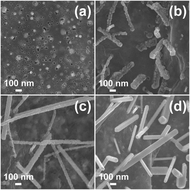
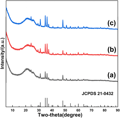
To figure out the formation process of FeSe2 nanorods, samples obtained at various selenization times are investigated. The morphology of FeSe2 varies considerably with increasing selenization times. Fig. 3a shows iron carbide nanoparticles located exactly in the pores of porous graphene. Ferric carbide is derived from the reaction between graphene and iron oxide, which originates from the pyrolysis of ferric nitrate. The formation of pores can be attributed to the carbothermal reaction between graphene and ferric nitrate.27–29 When the Fe3C@PG film is selenized at 400 °C for 4 h, an iron diselenide assembly composed of fine FeSe2 nanoparticles with a diameter of ∼30 nm is formed (Fig. 3b). With the increase of selenization time, iron diselenide nanoparticles continuously grow and a certain degree of fusion occurs. When the selenization time is 6 h, the FeSe2 nanorods with a small number of nanoparticles on the surface are formed (Fig. 3c). Finally, when the selenization time is 8 h, the FeSe2 nanorods with a smooth surface are obtained (Fig. 3d). According to the TG results, the contents of FeSe2 in FeSe2@PG-4, FeSe2@PG-6, and FeSe2@PG are 11.82%, 13.46%, and 17.23%, respectively (Fig. S1, ESI†). Fig. 4 depicts the typical XRD patterns of FeSe2@PG-4, FeSe2@PG-6, and FeSe2@PG. All the peaks match well with those of FeSe2 (JCPDS 21-0432). However, the intensities of the diffraction peaks of FeSe2 increase with the selenization time, indicating the progressive crystallization of iron diselenide. Therefore, it is reasonable to infer that the formation process of iron diselenide nanorods can be attributed to the oriented attachment (OA) mechanism.30–32 First, FeSe2 nanoparticles are formed on the surface of graphene. Second, FeSe2 nanoparticles move along graphene and connect with each other to form a corn-like FeSe2 assembly. Furthermore, FeSe2 nanoparticles continuously fuse to form nanorods with a few particles on the surface. Finally, FeSe2 nanorods with a smooth surface are formed with a further fusion of FeSe2 nanoparticles via atom-to-atom reorientations by the migration of grain boundaries or dislocations.32–34
Along with the formation of FeSe2 nanorods, some chemical connections between FeSe2 and graphene are formed, which is confirmed via XPS. FeSe2@PG-4, FeSe2@PG-6, and FeSe2@PG are all composed of C, O, Fe, and Se elements (Fig. 5a). The C 1s and Se 3d curves are fitted using the Gaussian–Lorentzian peak shape after a Shirley background correction. The C 1s spectra of three samples are fitted to the C (C![[double bond, length as m-dash]](https://www.rsc.org/images/entities/char_e001.gif) C/C–C) in aromatic rings (285 eV), the C in C–O (286.7 eV), the C in C–Se (285.5 eV), and the C in C
C/C–C) in aromatic rings (285 eV), the C in C–O (286.7 eV), the C in C–Se (285.5 eV), and the C in C![[double bond, length as m-dash]](https://www.rsc.org/images/entities/char_e001.gif) O (288.6 eV) bonds (Fig. 5b).35–37 With the extension of selenization time, the C–Se content increases from 15.0% (FeSe2@PG-4) to 25.1% (FeSe2@PG), indicating a stronger connection between graphene and FeSe2 in FeSe2@PG than in FeSe2@PG-4 and FeSe2@PG-6 (Tables S1 and S3, ESI†). To further analyze the interfacial interaction between graphene and FeSe2, the Se 3d spectra are investigated in detail (Fig. 5c). The spectra of three samples are fitted by six components at ca. 59.3, 57.9, 57.3, 56.5, 55.8, and 55.2 eV. The peak at 56.5 eV is attributed to Se–Se and that at 59.3 eV is attributed to Se–O.38,39 The peaks at 55.2 and 55.8 eV are attributed to the covalent bond between selenium and iron.40,41 In addition, the weak peak at around 57.9 eV is ascribed to C–Se–C. The middle peak at 57.3 eV corresponds to the interfacial interaction between FeSe2 and graphene,42 indicating the formation of C–Se–Fe bonds between the graphene and FeSe2. It is worth noting that the content of the C–Se–Fe covalent bond in FeSe2@PG is higher by 5.0% than that in FeSe2@PG-4 (Tables S2 and S4, ESI†). This implies that the interfacial interaction between FeSe2 and graphene is stronger in FeSe2@PG.
O (288.6 eV) bonds (Fig. 5b).35–37 With the extension of selenization time, the C–Se content increases from 15.0% (FeSe2@PG-4) to 25.1% (FeSe2@PG), indicating a stronger connection between graphene and FeSe2 in FeSe2@PG than in FeSe2@PG-4 and FeSe2@PG-6 (Tables S1 and S3, ESI†). To further analyze the interfacial interaction between graphene and FeSe2, the Se 3d spectra are investigated in detail (Fig. 5c). The spectra of three samples are fitted by six components at ca. 59.3, 57.9, 57.3, 56.5, 55.8, and 55.2 eV. The peak at 56.5 eV is attributed to Se–Se and that at 59.3 eV is attributed to Se–O.38,39 The peaks at 55.2 and 55.8 eV are attributed to the covalent bond between selenium and iron.40,41 In addition, the weak peak at around 57.9 eV is ascribed to C–Se–C. The middle peak at 57.3 eV corresponds to the interfacial interaction between FeSe2 and graphene,42 indicating the formation of C–Se–Fe bonds between the graphene and FeSe2. It is worth noting that the content of the C–Se–Fe covalent bond in FeSe2@PG is higher by 5.0% than that in FeSe2@PG-4 (Tables S2 and S4, ESI†). This implies that the interfacial interaction between FeSe2 and graphene is stronger in FeSe2@PG.
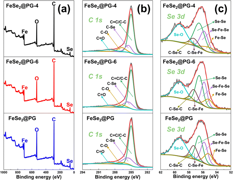 | ||
| Fig. 5 (a) XPS spectra of FeSe2@PG-4, FeSe2@PG-6, and FeSe2@PG and their (b) C 1s and (c) Se 3d spectra. | ||
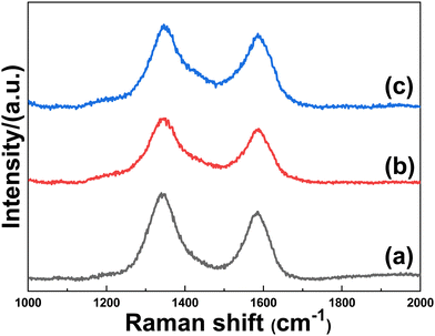
In order to further investigate the interfacial properties, Raman measurements were performed. Raman spectroscopy was used to characterize not only the defects of carbon nanomaterials but also the interfacial interaction between carbonaceous materials and metal-containing compounds.43Fig. 6 depicts a typical D (ca.1348 cm−1) and G (ca. 1586 cm−1) bands for carbon, and the intensity ratio of the D to the G bands (ID/IG) is used to measure the defects of carbon materials. The ID/IG ratios of FeSe2@PG-4, FeSe2@PG-6, and FeSe2@PG are 1.28, 1.19, and 1.12, respectively. The lower ID/IG ratio of FeSe2@PG implies a stronger interfacial interaction between graphene and FeSe2, which is consistent with the XPS results.43
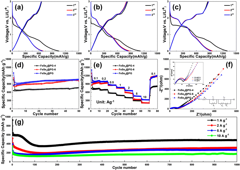
To investigate the effect of the interfacial interaction between graphene and FeSe2 on the electrochemical performance of FeSe2@porous graphene electrodes, the specific capacity, cycling and rate performance, and dynamic parameters of FeSe2@PG-4, FeSe2@PG-6, and FeSe2@PG as anode materials for LIBs were evaluated via galvanostatic charge/discharge measurements. Fig. 7a–c show the initial three discharge–charge curves of FeSe2@PG-4, FeSe2@PG-6, and FeSe2@PG at 100 mA g−1. It is worth noting that the initial coulombic efficiency is not high, as shown in Fig. 7a–c. The low initial coulombic efficiency can be attributed to the large irreversible capacity due to the formation of solid electrolyte interphase (SEI) films. Moreover, the defects and edges of porous graphene also decreases the initial coulombic efficiency of FeSe2@PG. To improve the coulombic efficiency, we can consider the following strategies. First, we can control the formation of SEI films or synthesize artificial SEI films. Second, defects of porous graphene can be controlled to reduce the initial irreversible capacity of FeSe2@PG. Finally, the initial coulombic efficiency can be improved by optimizing the electrolyte and the binder. The plateaus at 2.0, 1.5, and 1.0 V during discharge are attributed to the lithiation of FeSe2 to LixFeSe2 (FeSe2 + xLi+ + xe− → LixFeSe2), the conversion reaction of LixFeSe2 to Li2Se [LixFeSe2 + (2−x)Li+ + (2−x)e− → FeSe + Li2Se], and the further transformation of FeSe to Fe and Li2Se (FeSe + 2Li+ + 2e− → Fe + Li2Se), respectively.44–46 The slope below 0.5 V is due to lithium intercalation into the graphene layers.47 During the subsequent charging process, two plateaus are observed at 1.9 and 2.2 V, corresponding to Li+ extraction processes [Fe + 2Li2Se → LixFeSe2 + (4−x)Li+ + (4−x)e− and LixFeSe2 → FeSe2 + xLi+ + xe−].48 The reversible capacities of FeSe2@PG-4 and FeSe2@PG-6 are 662 and 829 mA h g−1 at 100 mA g−1, respectively. However, the specific capacity of FeSe2@PG increases to 858 mA h g−1 at the same current density. After 50 cycles, FeSe2@PG retains the reversible capacity of 1053 mA h g−1, whereas that of FeSe2@PG-4 is lower than 770 mA h g−1 at the same current density (Fig. 7d). Fig. 7e shows the rate capabilities of FeSe2@PG-4, FeSe2@PG-6, and FeSe2@PG at different current densities between 0.1 and 10 A g−1. The specific capacities of FeSe2@PG at 1, 2, 5, and 10 A g−1 are 774, 664, 458, and 328 mA h g−1, respectively. When the current density returns to 100 mA g−1, the capacity immediately returns to 1046 mA h g−1 and then increases to 1187 mA h g−1 after 80 cycles, indicating the excellent rate performance of the FeSe2@PG electrode (Fig. 7e). Fig. 7g shows that FeSe2@PG exhibits stable cycling performance even at high current densities. At 1 A g−1, the initial reversible capacity of FeSe2@PG is 606 mA h g−1. Notably, the specific capacity of FeSe2@PG gradually decreases in the initial 100 cycles, which can be attributed to the poor electrolyte wetting of the FeSe2@PG film. Subsequently, the specific capacity slowly increases and does not decay until 1000 cycles, which is due to the gradual electrolyte wetting.49 After 1000 cycles, the specific capacity remains at 483 mA h g−1. Even at higher current densities of 2, 5, and 10 A g−1, FeSe2@PG can still retain 313, 265, and 178 mA h g−1 after 1000 cycles, respectively. To analyze the better electrochemical performance of the FeSe2@PG electrode, the microstructural changes in FeSe2@PG-4, FeSe2@PG-6, and FeSe2@PG after the cycling test were determined and compared. Fig. S2 (ESI†) shows that FeSe2 in FeSe2@PG-4 and FeSe2@PG-6 changed into small nanoparticles without any regulation. However, in the FeSe2@PG electrode, FeSe2 retains the rod-like structure integrity even though small nanoparticles are formed during cycling, indicating that the FeSe2@PG electrode can resist the repeated intercalation and deintercalation of lithium ions during the charge/discharge process. It should be attributed to the stronger interfacial interaction between FeSe2 and graphene in FeSe2@PG than that in FeSe2@PG-4 and FeSe2@PG-6.
To elucidate the reasons for the differences in electrochemical performance, FeSe2@PG-4, FeSe2@PG-6, and FeSe2@PG electrodes are investigated using EIS (Fig. 7f). The charge-transfer resistance and film resistance of FeSe2@PG are lower than those of FeSe2@PG-4 and FeSe2@PG-6, which should be attributed to the strong interfacial interaction between FeSe2 and graphene in FeSe2@PG (Table S5, ESI†). In general, the excellent electrochemical performance of FeSe2@PG can be ascribed to the following reasons. First, graphene can form a complete conductive network, which helps in improving the charge transfer reaction at high rates. Second, the porous structure of graphene provides fast transport channels for lithium ions and electrons. Finally, C–Se–Fe covalent bonds formed between graphene and FeSe2 facilitate lithium ion diffusion and electron transfer. Therefore, the FeSe2@PG electrode exhibits excellent electrochemical performance, including high specific capacity, good rate capability, and outstanding cycling stability, when used as an anode in LIBs.
Conclusions
FeSe2@PG was prepared via the confined oriented growth of FeSe2 on a porous graphene film. Graphene acted as a substrate for the growth of FeSe2 nanorods and improved the conductivity of the overall electrode material. In addition, C–Se–Fe covalent bonds were formed at the interface between FeSe2 and graphene. The electrochemical performance of FeSe2@PG was positively correlated with the content of C–Se–Fe covalent bonds. When used as an anode material for lithium ion batteries, FeSe2@PG exhibited high capacity and excellent rate and cycle performance.Conflicts of interest
There are no conflicts to declare.Acknowledgements
This work was supported by the Science and Technology Plan of Beijing Municipal Education Commission (KM202210012008), the National Key Research and Development Program of China (2022YFB3805804 and 2022YFB3805802), and the Beijing Scholars Program (RCQJ20303).Notes and references
- F. Shaikh, Q. Ji and Y. Fan, Renewable Sustainable Energy Rev., 2015, 52, 1172–1185 CrossRef.
- B. Dunn, H. Kamath and J.-M. Tarascon, Science, 2011, 334, 928–935 CrossRef CAS PubMed.
- Y. Tang, Y. Zhang, W. Li, B. Ma and X. Chen, Chem. Soc. Rev., 2015, 44, 5926–5940 RSC.
- L. Ji, Z. Lin, M. Alcoutlabi and X. Zhang, Energy Environ. Sci., 2011, 4, 2682–2699 RSC.
- Y. Zhong, X. Xia, F. Shi, J. Zhan, J. Tu and H. J. Fan, Adv. Sci., 2016, 3, 1500286 CrossRef PubMed.
- X. Zhang, J. Zhou, H. Song, X. Chen, Y. V. Fedoseeva, A. V. Okotrub and L. G. Bulusheva, ACS Appl. Mater. Interfaces, 2014, 6, 17236–17244 CrossRef CAS PubMed.
- J. Ning, D. Zhang, H. Song, X. Chen and J. Zhou, J. Mater. Chem. A, 2016, 4, 12098–12105 RSC.
- H. Wu, S. Lu, S. Xu, J. Zhao, Y. Wang, C. Huang, A. Abdelkader, W. A. Wang, K. Xi, Y. Guo, S. Ding, G. Gao and R. V. Kumar, ACS Nano, 2021, 15, 2506–2519 CrossRef CAS PubMed.
- X. Li, H. Wu, C. Guan, A. M. Elshahawy, Y. Dong, S. J. Pennycook and J. Wang, Small, 2019, 15, 1803895 Search PubMed.
- C. Xia, Q. Jiang, C. Zhao, P. M. Beaujuge and H. N. Alshareef, Nano Energy, 2016, 24, 78–86 CrossRef CAS.
- W. Xin, N. Chen, Z. Wei, C. Wang, G. Chen and F. Du, Chem. – Eur. J., 2021, 27, 3745–3752 CrossRef CAS PubMed.
- B. Cong, S. Sun, B. Wang, C. Lv, J. Zhao, F. Jin, J. Jia and G. Chen, Chem. Eng. J., 2022, 435, 135185 CrossRef CAS.
- Z. Liang, M. Yang, S. Wang, B. Chang, H. Tu, Y. Shao, B. Zhang, H. Zhao, Y. Lei and J. Shen, Chem. Eng. J., 2021, 405, 126724 CrossRef CAS.
- Q. Ma, L. Zhang, Y. Ding, X. Shi, Y. L. Ding, J. Mujtaba, Z. Li and Z. Fang, J. Colloid Interface Sci., 2022, 622, 840–848 CrossRef CAS PubMed.
- F. Bonaccorso, L. Colombo, G. Yu, M. Stoller, V. Tozzini, A. C. Ferrari, R. S. Ruoff and V. Pellegrini, Science, 2015, 347, 1246501 CrossRef PubMed.
- Y. Shao, M. F. El-Kady, L. J. Wang, Q. Zhang, Y. Li, H. Wang, M. F. Mousavi and R. B. Kaner, Chem. Soc. Rev., 2015, 44, 3639–3665 RSC.
- F.-Y. Su, Y.-B. He, B. Li, X.-C. Chen, C.-H. You, W. Wei, W. Lv, Q.-H. Yang and F. Kang, Nano Energy, 2012, 1, 429–439 CrossRef CAS.
- Y. Yang, Q. Lin, B. Ding, J. Wang, V. Malgras, J. Jiang, Z. Li, S. Chen, H. Dou, S. M. Alshehri, T. Ahamad, J. Na, X. Zhang and Y. Yamauchi, Carbon, 2020, 167, 627–633 CrossRef CAS.
- J.-Q. Huang, X.-F. Liu, Q. Zhang, C.-M. Chen, M.-Q. Zhao, S.-M. Zhang, W. Zhu, W.-Z. Qian and F. Wei, Nano Energy, 2013, 2, 314–321 CrossRef CAS.
- W. Ye, K. Wang, W. Yin, W. Chai, B. Tang and Y. Rui, Electrochim. Acta, 2019, 323, 134817 CrossRef CAS.
- P. Jing, Q. Wang, B. Wang, X. Gao, Y. Zhang and H. Wu, Carbon, 2020, 159, 366–377 CrossRef CAS.
- Z. Zhao, X. Teng, Q. Xiong, H. Chi, Y. Yuan, H. Qin and Z. Ji, Sustainable Mater. Technol., 2021, 29, e00313 CrossRef CAS.
- Z. Niu, P. Luan, Q. Shao, H. Dong, J. Li, J. Chen, D. Zhao, L. Cai, W. Zhou and X. Chen, Energy Environ. Sci., 2012, 5, 8726–8733 RSC.
- T. Jin, Q. Han and L. Jiao, Adv. Mater., 2020, 32, 1806304 CrossRef CAS PubMed.
- W. S. Hummers Jr and R. E. Offeman, J. Am. Chem. Soc., 1958, 80, 1339 CrossRef.
- X. Zhang, J. Zhou, X. Chen and H. Song, ACS Appl. Energy Mater., 2018, 1, 48–55 CrossRef CAS.
- D. Zhou, Y. Cui, P.-W. Xiao, M.-Y. Jiang and B.-H. Han, Nat. Commun., 2014, 5, 4716 CrossRef CAS PubMed.
- H. Cao, X. Zhou, C. Zheng and Z. Liu, Carbon, 2015, 89, 41–46 CrossRef CAS.
- X. Zhang, J. Zhou, C. Liu, X. Chen and H. Song, J. Mater. Chem. A, 2016, 4, 8837–8843 RSC.
- R. L. Penn and J. F. Banfield, Science, 1998, 281, 969–971 CrossRef CAS PubMed.
- G. Zhang, K. Liu, S. Liu, H. Song and J. Zhou, J. Alloys Compd., 2018, 731, 714–722 CrossRef CAS.
- D. Li, J. Zhou, X. Chen and H. Song, ACS Appl. Mater. Interfaces, 2018, 10, 22841–22850 CrossRef CAS PubMed.
- X. Zhang, J. Zhang, J. Zhao, B. Pan, M. Kong, J. Chen and Y. Xie, J. Am. Chem. Soc., 2012, 134, 11908–11911 CrossRef CAS PubMed.
- L. Zhu, B. J. Richardson and Q. Yu, Chem. Mater., 2015, 27, 3516–3525 CrossRef CAS.
- Y. Li, Y. Xu, Z. Wang, Y. Bai, K. Zhang, R. Dong, Y. Gao, Q. Ni, F. Wu, Y. Liu and C. Wu, Adv. Energy Mater., 2018, 8, 1800927 CrossRef.
- M. Ren, H. Zang, S. Cao, H. Guo, J. Zhang, W. Liu, J.-S. Yao, X. Zhang and Z. Zhou, J. Mater. Chem. A, 2023, 11, 10435–10444 RSC.
- X. Zhang, J. Zhou, H. Song, C. Liu, S. Zhang and X. Chen, Carbon, 2016, 99, 370–374 CrossRef CAS.
- R. Manikandan, C. Justin Raj, G. Nagaraju, R. Velayutham, S. E. Moulton, J. Puigdollers and B. Chul Kim, Chem. Eng. J., 2021, 414, 128924 CrossRef CAS.
- J. Feng, S.-H. Luo, S.-X. Yan, Y. Zhan, Q. Wang, Y.-H. Zhang, X. Liu and L.-J. Chang, J. Mater. Chem. A, 2021, 9, 1610–1622 RSC.
- P. Ge, H. Hou, S. Li, L. Yang and X. Ji, Adv. Funct. Mater., 2018, 28, 1801765 CrossRef.
- S. Jiang, M. Xiang, J. Zhang, S. Chu, A. Marcelli, W. Chu, D. Wu, B. Qian, S. Tao and L. Song, Nanoscale, 2020, 12, 22210–22216 RSC.
- F. Jin, M. Li, L. Xie and J. Jiang, J. Power Sources, 2021, 514, 230587 CrossRef CAS.
- X. Zhang, C. Liu and R. Wang, Sustainable Energy Fuels, 2021, 5, 2469–2476 RSC.
- W. Zhao, Q. Tan, K. Han, D. He, P. Li, M. Qin and X. Qu, J. Phys. Chem. C, 2020, 124, 12185–12194 CrossRef CAS.
- T. Liang, H. Wang, R. Wang, B. He, Y. Gong and C. Yan, Electrochim. Acta, 2021, 389, 138686 CrossRef CAS.
- H. Wang, X. Wang, Q. Li, H. Li, J. Xu, X. Li, H. Zhao, Y. Tang, G. Zhao and H. Li, ACS Appl. Mater. Interfaces, 2018, 10, 38862–38871 CrossRef CAS PubMed.
- J. Zhou, L. Ma, H. Song, B. Wu and X. Chen, Electrochem. Commun., 2011, 13, 1357–1360 CrossRef CAS.
- J. Wang, F. Kong, J. Chen, Z. Han, S. Tao, B. Qian and X. Jiang, ChemElectroChem, 2019, 6, 2805–2811 CrossRef CAS.
- C. Masarapu, V. Subramanian, H. Zhu and B. Wei, Adv. Funct. Mater., 2009, 19, 1008–1014 CrossRef CAS.
Footnote |
| † Electronic supplementary information (ESI) available: The TG curves of FeSe2@PG-4, FeSe2@PG-6, and FeSe2@PG. The SEM images of FeSe2@PG-4, FeSe2@PG-6, and FeSe2@PG electrodes after cycling. The area and area ratio of different covalent bonds in the C 1s and Se 3d spectra of FeSe2@PG-4, FeSe2@PG-6, and FeSe2@PG. The AC impedance resistances of FeSe2@PG-4, FeSe2@PG-6, and FeSe2@PG. See DOI: https://doi.org/10.1039/d3ma00269a |
| This journal is © The Royal Society of Chemistry 2023 |

