 Open Access Article
Creative Commons Attribution 3.0 Unported Licence
Rheological study of Hall current and slip boundary conditions on fluid–nanoparticle phases in a convergent channel
Mubbashar
Nazeer
a,
M. Ijaz
Khan
 *bc,
Sherzod
Abdullaev
de,
Fuad A.
Awwad
f and
Emad A. A.
Ismail
f
aDepartment of Mathematics, Institute of Arts and Sciences, Government College University Faisalabad Chiniot Campus, 35400, Pakistan. E-mail: mubbasharnazeer@gcuf.edu.pk
bDepartment of Mechanics and Engineering Science, Peking University, Beijing, China. E-mail: 2106391391@pku.edu.cn
cDepartment of Mechanical Engineering, Lebanese American University, Beirut, Lebanon
dFaculty of Chemical Engineering, New Uzbekistan University, Tashkent, Uzbekistan
eDepartment of Science and Innovation, Tashkent State Pedagogical University Named After Nizami, Bunyodkor Street 27, Tashkent, Uzbekistan. E-mail: sherzodbek.abdullaev.1001@gmail.com
fDepartment of Quantitative Analysis, College of Business Administration, King Saud University, P.O. Box 71115, Riyadh 11587, Saudi Arabia. E-mail: fawwad@ksu.edu.sa; emadali@ksu.edu.sa
First published on 24th October 2023
Abstract
Purpose: the purpose of this theoretical study was to analyze the heat transfer in the fluid–particle suspension model under the effects of a porous medium, magnetic field, Hall effects, and slip boundary conditions in a convergent channel with the addition of electrokinetic phenomena. The Darcy–Brinkman (non-Darcy porous medium) model was used to assess the effects of the porous medium. Methodology: the rheological equations of both models were transformed into a dimensionless form to obtain the exact solutions of the fluid and particle phase velocities, pressure gradient, volumetric flow rate, stream function, temperature distribution, and heat-transfer rate. To obtain an exact solution to the models, the physical aspects of the parameters are discussed, analyzed, and reported through graphs, contour plots, and in tabular form. Findings: mixing in hafnium particles in a viscous fluid provide 1.2% more cooling compared to with a regular fluid. A reduction of the streamlines was observed with the contribution of the slip condition. The utilization of the Darcy parameters upgraded both the fluid flow and temperature profiles, while the heat-transfer rate decreased by up to 3.3% and 1.7% with the addition of a magnetic field and porous medium, respectively. Originality: the current study is an original work of the authors and has not been submitted nor published elsewhere.
1. Introduction
Colloidal suspensions of nanoparticles generated by carbides, metal oxides, etc. appearing in a regular fluid (such as water, glycol, oil, and ethylene) can form a nanofluid. Much research is devoted to the search for different types of nanoparticles that have good mechanical properties (i.e., thermal conductivity, a certain size of the particles, low particle momentum, and high mobility) to promote the heat-transfer analysis of the systems. Due to the distinguished properties of nanoparticles to increase heat transfer, nanofluids are used in various scientific processes (such as electronics, nuclear reactors, and biomedicine). The nanoparticles are also effectively used in many chemical processes and modern biotechnology (such as, artificial heart surgery, cancer therapy, drug delivery, sensor technology, disease diagnosis, and brain tumor therapy, due to their extensive thermophysical properties. Various researchers have performed work on different types of nanoparticles and base fluids in many diverse shapes of geometries to highlight the applications of nanofluids. For instance, Ellahi et al.1 reported the applications of nanoparticles in a cooling process. They considered the spherical shape of aluminum nanoparticles in kerosene oil (as a base fluid) with a maximum volume fraction of 4% to promote their applications in the cooling process. Bhatti et al.2 used a suspension of cobalt oxide and graphene nanoparticles in a carrier fluid to examine the applications of nanofluids in solar energy. They employed a successive linearization method to obtain numerical solutions to the problem. Their findings revealed that both nanoparticles could upgrade the heat-transfer rate, while skin friction displayed the opposite behavior. Hussain et al.3 suspended gold nanoparticles in a couple of stress fluids to discover their applications in gland and tumor remedies. They used a semi-analytical technique to obtain computational results for their model. Their results revealed that gold nanoparticles are the best option to kill the affected cells of tumors or glands due to their larger atomic number. Xu et al.4 showed the brilliant advantages of ultrasmall-sized nanoparticles in biomedical engineering (tumor therapy) and showed that nanoparticles sized less than 7 nm were more effective in kidney and tumor treatment compared to larger-sized nanoparticles (100–200 nm). Aljohani et al.5 chose a fractional derivative approach to show the applications of different types of nanoparticles in solar collectors to store solar energy. Some important results of nanofluids in different configurations were also reported by Dharmaiah et al.6–8 and Vedavathi et al.9Fluid and heat transfer in a porous medium are attracting increasing interest from researchers due to their wider applications in geothermal systems, food industries, the insulation of buildings, the design of nuclear reactors, the manufacturing of thermal isolators, oil production, solar power reactors, hot rolling, drying technologies, the control of pollutant spread in groundwater, and in compact heat exchangers,10–13etc. Various models have been proposed by different authors to simulate the porous medium effects, such as Darcian and non-Darcian models, and non-equilibrium models. In 1856, Darcy proposed the porous medium model for assessing fluid flow through a porous medium experimentally by considering the linear relationship between the drop in pressure and the flow rate. The extensive body of literature suggests the importance of the porous medium in heat and flow analysis. For instance, Al Hajri et al.14 analyzed the importance of the porous medium in the heat-transfer analysis of a Maxwell fluid through a square conduit. The applications of a porous medium with heat transfer along a stretched cylinder were provided by Reddy et al.15 Asghar et al.16 used the Sisko fluid model to discuss the heat transfer with the porous medium in a curved channel by using the implicit finite difference method. Ramesh17,18 chose a non-uniform tilled channel model to discuss peristaltic flow under the influence of a porous medium and presented an exact solution to the problem.
Various engineering applications of heat transfer with porous media have been observed where cooling or heating is a very important factor, such as combustion systems, the cooling of turbine blades, the cooling of electronic devices, chemical reactors, storage in thermal-transport systems, and composite fabrication. The mixtures of low or high thermal fluids that appear in such applications can affect the output of these devices. In this situation, this issue can be resolved, and the performance of these devices can be increased (i.e., the heat transfer) by utilizing a porous medium with nanofluids. Zhao et al.22 conducted a study on the utilization of Mg gas infiltration to produce MgB2 pellets, incorporating micro-sized B and nanosized powders. Zhang et al.23 investigated the energy absorption of water jet penetration on the 2A12 aluminum alloy. Chen et al.24 focused on the significance of the first hidden-charm pentaquark in relation to its strangeness. Also, the applications of nanofluids with a porous medium in heat-transfer analysis were reported by Nabway et al.,19 Kasaeian et al.,20 Mahdi et al.,21 Hussain et al.,25,26 Ge-JiLe et al.27 Cai et al.,28 Chen,29 and Du et al.30 in recent works on the applications of nanofluids in different applied fields.
The influences of the slip boundary conditions on the heat-transfer analysis of a fluid–particle suspension of a magnetohydrodynamic (MHD) electro-osmotic flow of a rheological fluid through a convergent shape geometry with a porous medium and the Hall effect have not been considered yet. Yet, we were motivated investigate these because of the potential applications of the slip boundary conditions in electro-osmotic flow to aid the design of reliable microfluidic devices and to ensure the effective operation of such devices. Here, the problem of slip boundary conditions can have a significant role in the study of heat and flow analysis to characterize the behavior of micro- and nanofluids through a microchannel. Currently, “no-slip” conditions are commonly used in the problem of microfluidic flows, but a key limitation of the no-slip condition is that it may fail to solve micro-, nanoscale fluid problems (depending on the roughness interface and the fluid–solid interface interaction).31 Due to this reason, it is important to use the slip boundary conditions during the study of the flow of fluids in a microchannel. It was Navier who first presented the slip boundary condition, in which he reported a linear relationship between the wall shear rate and the velocity of the slip. After his development, different researchers presented different types of slip boundary conditions,32 but the Navier slip boundary conditions are most commonly used due to their easiness and reliability. This article reports the solution of a fluid–particle suspension of an MHD electro-osmotic flow with heat transfer analysis of a rheological fluid under the consideration of the slip boundary conditions, porous medium, and Hall effects through a convergent geometry. In prior research, the crystallographic orientation, precipitation, mechanical characteristics, and phase transformation of a Ni-rich NiTi alloy were investigated by Wang et al.47 The authors examined the effects of the deposition current for a dual-wire arc on the alloy's properties. In recent studies, Zhao48 and Zhang et al.49 also explored the applications of co-precipitated Ni/Mn shell-coated nano Cu-rich core structures and analyzed the microstructural properties of alkali-activated composite nanomaterials. Additionally, Lu et al.50 and Kong et al.51 emphasized the importance of thermo-electric thermal fluid flows and conducted microspectroscopy analysis under high pressure.
2. Mathematical analysis
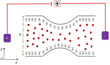
Consider the time-independent flow of a rheological fluid suspended by the addition of 40% hafnium solid spherical particles in as convergent channel as shown in Fig. 1. Here, Vvf = [uvf(x,y),vvf(x,y),0] and Vvp = [uvp(x,y),vvp(x,y),0] are the velocity vectors of the fluid and particulates.The following assumptions are taken to simplify the given flow problem.
1. An external electric field Ex is applied along the x-axis direction.
2. The Debye–Hückel linearization approximation is applied.
3. The flow is considered in the Cartesian coordinate systems in which x and y are chosen in the axial and normal-to-flow directions, respectively.
4. The fluid is electrically conducted while the channel is non-electrically conducted.
5. A constant magnetic field B0 is applied normal to the flow direction.
6. The magnetic Reynolds number is very small, so the induced magnetic field is negligible.
7. The Hall current is considered while the ion slip effects and buoyancy force are neglected.
8. The flow and particle interact as a continuum.
9. The fluid and particle velocities are irrotational.
10. The Joule heating and thermal radiative heat flux effects are omitted.
11. The flow is symmetric along the center line of the channel y = 0 while y = h(x) and y = −h(x) are the upper and lower boundaries of the divergent channel, respectively.
12. The hafnium particles are considered to be in a spherical shape with equal size and uniformly distributed in the fluid.
13. The fluid and hafnium particles are coupled in terms of the drag force and heat transfer between them.
14. The top and lower walls of the channel maintain the temperatures T0 and T1, respectively.
 | (1) |
2.1 Physical model of the fluid phase
The rheological equations for the fluid phase in the vector form are defined as33,34 | (2) |
 | (3) |
The Darcy resistance R = (RX,RY,0), the electric current J = (JX,JY,0), and the Cauchy stress tensor Tij are expressed in the following form:
 | (4) |
 | (5) |
| TijμsA, A = ∇V + (∇V)T. | (6) |
 | (7) |
From the above eqn (7), we have
| Jx = σeB0Vvf − m1Jy, | (8) |
| Jy = σeB0Uvf − m1Jx,…, | (9) |
 | (10) |
 | (11) |
In eqn (10) and (11), Jx and Jx are the components of the current vector J in the x- and y- directions, respectively while m is the Hall current parameter.
2.2 Physical model of the particle phase
The rheological equations for the particle phase in vector form are defined as39,40 | (12) |
 | (13) |
The vector form of the heat equation with viscous dissipation effects is defined as41
 | (14) |
The components form of the fluid and particle phases flow equations are defined as
 | (15) |
 | (16) |
 | (17) |
 | (18) |
 | (19) |
 | (20) |
 | (21) |
The boundary conditions are
 | (22) |
 | (23) |
Introducing the dimensionless variable to convert the above-governing equations into dimensionless form
 | (24) |
In view of the above equation, the dimensionless fluid–particle phase problem is expressed as (the bar has been removed)
 | (25) |
 | (26) |
 | (27) |
 | (28) |
 | (29) |
 | (30) |
The boundary conditions are
 | (31) |
 | (32) |
 | (33) |
In eqn (24),  is called the magnetic field parameter,
  is known as the porous medium parameter, Df is the drag force, and Br is called the Brinkman number.
The exact solution, i.e., the exact expressions for the fluid, particle, and temperature, is expressed as
The expression of the total volumetric flow is obtained from the following mathematical expression as
 | (36) |
 | (37) |
Solving the above equation for dp/dx gives
 | (38) |
The expression of the stream function is calculated from the following mathematical relation  and given as
 | (39) |
The expression of temperature distribution can be obtained from eqn (17) with boundary conditions (21)
 | (40) |
As an important physical quantity, the heat-transfer rate is calculated by using the relation  and allows obtaining the following analytical expression:
 | (41) |
The constants G1,G2,G3,G4,G5, and R1,R2,…,R22 are defined in the appendix.
3. Particular cases
1. It is interesting to note that for am → 0, the problem is reduced to the single phase of an MHD electro-osmotic Newtonian fluid flow with heat transfer analysis in a convergent channel under the effects of slip boundary conditions, a porous medium, and Hall current without hafnium particles.2. When m1 → 0, the problem is reduced to the multiphase electro-osmotic flow of a Newtonian fluid with heat-transfer analysis in a convergent channel under the effects of slip boundary conditions, a porous medium, and a magnetic field with a 40% suspension of Hafnium particles.
3. The finite value of Dp → ∞ corresponds to heat-transfer analysis of a biphase liquid flow of an MHD Newtonian fluid under the action of the Hall current and slip boundary conditions in a convergent channel with a 40% suspension of hafnium particles.
4. For m0 → 0, the problem is transformed into a simple multiphase pressure-driven flow of an MHD Newtonian fluid with heat-transfer analysis under the impact of the Hall current and slip boundary conditions in a convergent channel with a 40% suspension of hafnium particles.
5. When Ha → 0, the problem is reduced to the thermal transport of an MHD Newtonian fluid with a porous medium in a fluid–particle suspension through a convergent channel under the influence of the slip boundary conditions and Hall current.
6. For vs = tp = 0, the problem is reduced to thermal analysis of an MHD Newtonian fluid in a fluid–particle suspension in convergent channels without wall properties.
7. When Dp → ∞ and m1 = 0, the results of Hussain et al.33 and Ellahi et al.34 can be recovered, i.e., the flow of a Newtonian nanofluid through a convergent channel without a heat-transfer mechanism.
4. Results and discussion
In this section, we analyze the graphical behavior of the important physical quantities, namely the fluid and particle velocities, stream function, temperature distribution, and heat-transfer rate under the involved parameters of the study, namely the Debye length parameter , magnetic parameter
  , Hall parameter (m1 = ωeτe), velocity slip parameter
  , Darcy parameter
  , Brinkman number
  , particle suspension parameter (am), and thermal slip parameter
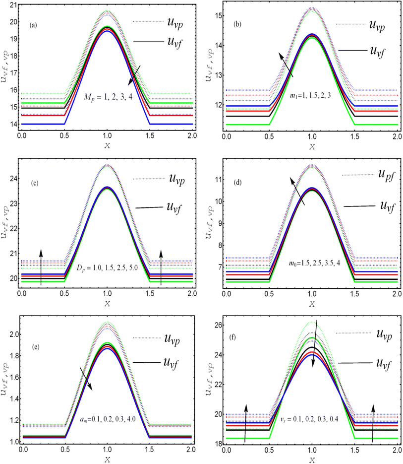
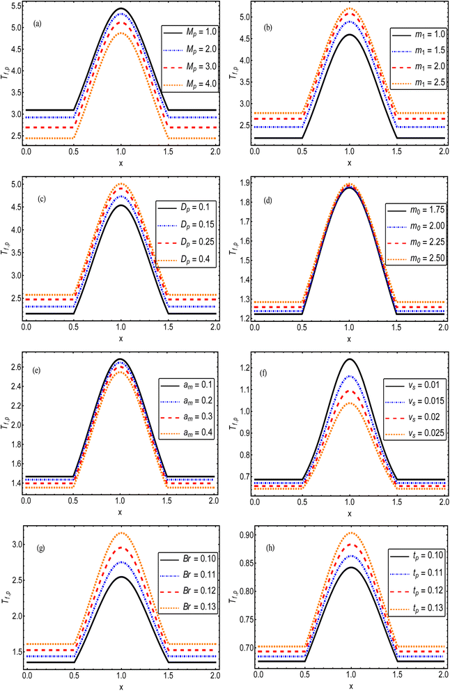
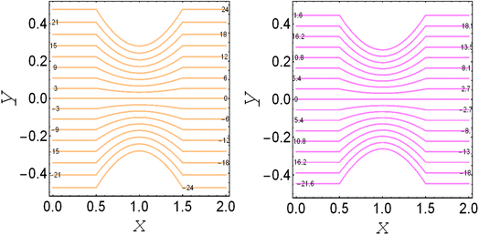
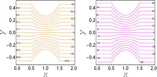
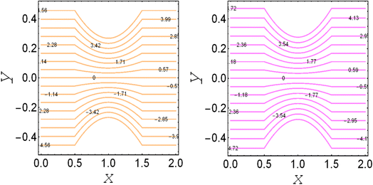
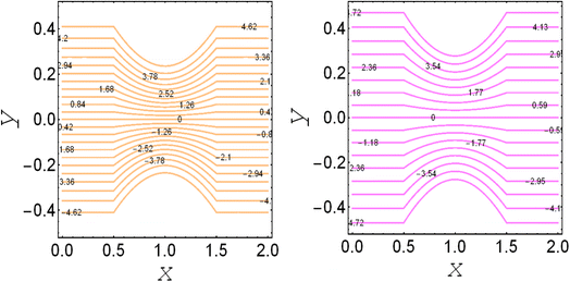
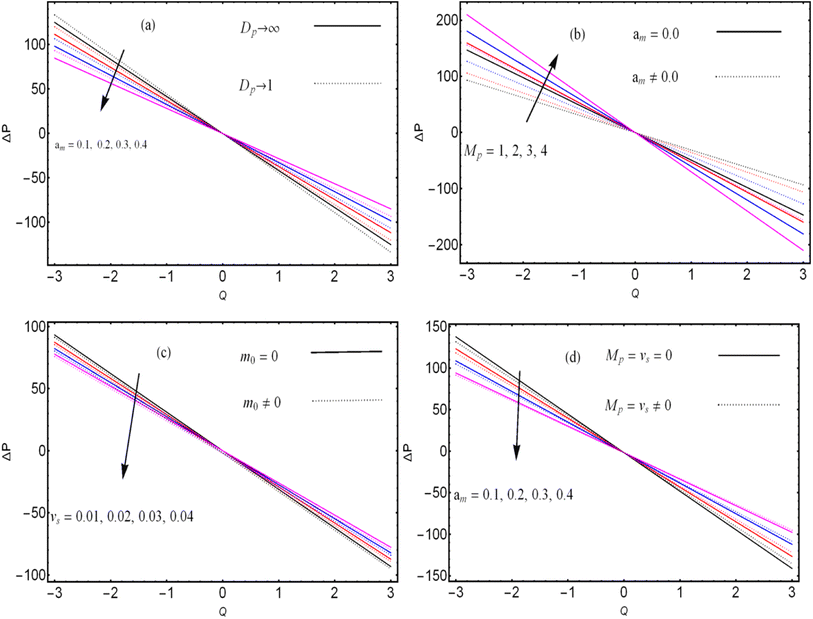
  . The solution to the considered problem is obtained with the help of mathematical software and presented as closed-form expressions of the fluid and particle velocity, stream function, total volumetric flow rate, pressure gradient, temperature distribution, and local heat-transfer rate. The range of the involved parameters for computation results is listed in Table 1. The author present seven figures. Fig. 2 shows the variation of the fluid and particle velocities, while Fig. 3 reports the temperature distribution, Fig. 4–7 show the stream function behavior, and the graphs of the pressure rise are displayed in Fig. 8. The variation of heat-transfer rate is presented in Table 2.
| Name | Notation | Range | Reference |
|---|---|---|---|
| Debye length parameter | m 0 | [0,10] | 42 |
| Hall parameter | m 1 | [0,3] | 43 |
| Thermal slip parameter | t p | [0,0.1] | 44 |
| Brinkman number | Br | [0,10] | 27 |
| Velocity slip parameter | υ s | [0,0.1] | 44 |
| Magnetic field parameter | M p | [0,5] | 45 |
| Darcy parameter | D p | [0,∞] | 10–13 |
| Electro-osmotic velocity | U hs | [0,10] | 33 and 34 |
| Coefficient of particle fraction | α m | [0,0.6] | 46 |
| α m | υ s | t p | m 0 | m 1 | Br | D p | M p | H tr | % | Behavior |
|---|---|---|---|---|---|---|---|---|---|---|
| 0.0 | 0.1 | 0.1 | 1.0 | 1.0 | 0.1 | 1.0 | 1.0 | 4.9197 | 1.2 | Decrease |
| 0.4 | — | — | — | — | — | — | — | 4.8614 | ||
| 2.0 | 0.0 | — | — | 5.0 | — | — | — | 14.4155 | 8.7 | Decrease |
| — | 0.01 | — | — | — | — | — | — | 13.1587 | ||
| — | 0.1 | 0.0 | — | — | — | — | — | 7.0139 | 2.4 | Increase |
| — | — | 0.1 | — | — | — | — | — | 7.1805 | ||
| — | — | — | 0.0 | — | — | — | — | 7.0904 | 1.3 | Increase |
| — | — | — | 1.0 | — | — | — | — | 7.1805 | ||
| — | — | — | — | 0.0 | — | — | — | 4.8884 | 2.6 | Increase |
| — | — | — | — | 2.0 | — | — | — | 5.0152 | ||
| — | — | — | — | 1.0 | 0.1 | — | — | 16.7042 | 53.8 | Increase |
| — | — | — | — | — | 0.15 | — | — | 25.6926 | ||
| — | — | — | — | — | 0.1 | ∞ | — | 4.9851 | 1.7 | Decrease |
| — | — | — | — | — | — | 1.0 | — | 4.8979 | ||
| — | — | — | — | — | — | 1.0 | 0.0 | 4.9408 | 3.3 | Decrease |
| — | — | — | — | — | — | — | 2.0 | 4.7768 |
The effects of the magnetic field parameter (Mp) on both the fluid and particle velocities are displayed in Fig. 2(a). The dashed and solid lines are used in the graphs to differentiate the particle and fluid velocity distribution, respectively. This figure shows that increasing the magnetic field parameter led to decreases in both velocities in the divergent channel, and this behavior was due to resistive force i.e., Lorentz force (J × B). Basically, the greater the values of the magnetic field parameter, the larger the magnetic field produced relative to the viscosity of the fluid, which enhances the Lorentz force acting on the fluid particles and reduces the motion of the fluid particles. The influence of the Hall parameter on the velocity distribution is highlighted in Fig. 2(b). Here we observed that the Hall parameter and magnetic field had a direct and inverse relation on the velocity profiles, respectively, i.e., the magnetic field parameter disturbed the fluid flow, which caused a reduction in the fluid velocity, while the Hall parameter supported the motion of the fluid particle, and the velocities distribution increased against it. Since m1 = ωeτe, i.e., the cyclotron frequency of electrons and the electron collision time have a direct relationship with the Hall parameter, which means that when the Hall parameter is increased, then the cyclothron frequency of the electrons in the fluid particles increases, which causes an increase in both velocities' distribution. This can also be expressed by another mathematical relation  , i.e., the greater values of the Hall parameter diminish the electrical conductivity, which causes a reduction in the damping force, and as a result the velocity of both phases increases against the Hall parameter. Fig. 2(c) shows the increasing behavior of the velocity distribution against the Darcy parameter (Dp). Physically, this means that the Darcy parameter reduces the drag force in the fluid particles, which causes an enhancement in the velocity profile via the Darcy parameter. We can also express that, for increasing values of the Darcy parameter, a more permeable porous medium will exist, which will provide less resistance to the fluid particles as a result of the velocities profiles enhancement. The effects of the Debye length parameter (m0) on the velocities are examined in Fig. 2(d), in which the increasing trend of the velocities distribution is captured against this parameter. Since the Debye length parameter
  , i.e., the Debye length parameter is defined as “the height of the channel (a) over the Debye thickness (λd)”, when the height of the channel increases, then the velocity distribution will increase, and as a result an electrical double layer arises. The effects of the coefficient of the volume fraction on velocity profiles are shown in Fig. 2(e), in which the velocity profiles decrease when increasing the coefficient of the volume fraction. From the computational results, it was observed that the velocity of the clean/simple fluid was greater than the velocity of the multiphase fluid (i.e., the fluid with the suspension of hafnium particles). The physical reason for this is that when the solid tiny particles of hafnium are mixed in simply, then these particles generate internal friction in the resultant fluid (multiphase fluid), which retards the fluid flow. Fig. 2(f) was constructed to analyze the impact of the velocity slip parameter on the fluid–particle phase velocities. From this figure, it can be noted that the velocity of both phases showed a mixed behavior via the velocity slip parameter, i.e., the velocity profiles increased and decreased in the interval x ∈ [0,0.65]U[1.35,2.0] and x ∈ [0.65,1.35], respectively.
The impact of the magnetic field parameter  on the temperature distribution is illustrated in Fig. 3(a), which shows the inverse relationship between the temperature profile and the magnetic field parameter. It could be observed that the hafnium particles lost their temperature when the magnetic force was applied, and we can also say that the reduction in temperature distribution happened due to departing effects. Fig. 3(b) depicts the influence of the Hall parameter (m1 = ωeτe) on the temperature profile, and we could observe that this parameter enhanced the temperature distribution, and the maximum temperature was noted to be in the center of the channel. The variations of temperature against the Darcy parameter
  and Debye length parameter
  are shown in Fig. 3(c) and (d), respectively. Both figures indicate the direction variation of the temperature profiles with these parameters. Fig. 3(e) and (f) exhibit the impact of the coefficient of the volume fraction (am) and velocity slip parameter
  on the temperature of the fluids and particles, respectively. Both figures show the decreasing behavior of the temperature distribution via the coefficient of the volume fraction and velocity slip parameter. The physical reason is that when hafnium particles are suspended in the fluid, they absorb the heat, and as a result, the temperature decreases. Thus, we can say that the viscous fluid with the suspension of hafnium particles plays a significant role in the cooling process compared to in a regular viscous fluid. Fig. 3(g) and (h) characterize the temperature behavior against the Brinkman number
  and thermal slip parameter
  . These figures show increasing trends via considering the Brinkman number and thermal slip parameter. The physical reason for the increasing temperature against the Brinkman number is that when the Brinkman number increases, the viscous dissipation produces the condition of the heat-transfer mode, which enhances the temperature profile. The impacts of the magnetic parameter, Darcy parameter, Hall parameter, and velocity slip parameter on the stream function are captured in Fig. 4–7, respectively. From these figures, a significant change can be observed in the stream function graphs. The magnitude of the stream is reduced with the contribution of the magnetic field, which happened due to the Lorentz force produced against the applied magnetic field (see Fig. 4). On the other hand, the Darcy parameter controls the magnitude of the stream function, i.e., the stream function obtains a greater magnitude with consideration of a porous medium as compared to a clear medium (see Fig. 5). A similar trend for the stream function was recorded against the Hall current parameter and velocity slip parameter (see Fig. 6 and 7). The variation of the heat-transfer rate under the effects of the parameters of the study is shown in Table 2. From this table, it can be noted that there was a 1.2% reduction in the heat-transfer rate in the case of the suspension with hafnium particles, suggesting that the hafnium particles absorb heat when they are suspended in viscous fluid. Thus, the hafnium particles provided 1.2% greater cooling when they were mixed in the viscous fluid compared to a regular fluid. The percentage reduction in heat transfer against the velocity parameter was 8.7%, which means that the velocity slip parameter controlled the heat transfer of the system i.e., the slip parameter provided 8.7% more cooling compared to the case without slip conditions. The heat-transfer rate also decreased by up to 3.3% and 1.7% with the addition of a magnetic field and porous medium, respectively. These results suggest that these parameters also favor the cooling process of the system. The thermal slip parameter, Debye length parameter, Hall parameter, and Brinkman number thus support the heat-transfer rate, i.e., these parameters increase the heat transfer rate when increasing these parameters, and the percentages heat transfers were 2.4%, 1.3%, 2.6%, and 53.8%, respectively, see Table 2. Thus, the thermal slip parameter, Debye length parameter, Hall parameter, and Brinkman number favor the heating system. Fig. 8 illustrates an analysis of the characteristics of the pumping phenomena. It could be observed that the pressure rise decreased in the region 0 < Q & 0 < ΔP (i.e., the retrograde pumping region) and increased in the region Q > 0 & ΔP > 0 (i.e., the co-pumping region) when increasing the coefficient of the volume fraction and the Darcy parameter (see Fig. 8(a)). The pressure rise also increased via the magnetic field parameter in the retrograde pumping region (Q > 0 & ΔP > 0) and decreased via the magnetic field parameter in the co-pumping region (0 < Q & 0 < ΔP), see Fig. 8(b). Fig. 8(c) examines the behavior of the pressure rise against the velocity slip parameter for m0 = 0 and m0 ≠ 0 and it could be noted that the pressure rise showed a similar trend against the velocity slip parameter and Debye length parameter, as can be seen in Fig. 8(a). Considering the characteristics of the pressure rising versus the coefficient of the volume fraction for the two different cases, i.e., when the magnetic field and slip conditions are ignored, and when the magnetic field and slip conditions are included, we see that the pressure rise decreased in the region 0 < Q & 0 < ΔP (i.e., the retrograde pumping region) and increased in the region Q > 0 & ΔP > 0 (i.e. the co-pumping region) when increasing the coefficient of the volume fraction (see Fig. 8(d)).
5. Solution validation
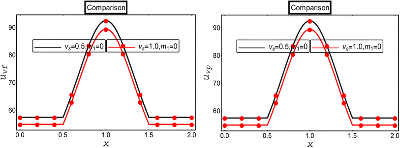
A comparative analysis was performed with the existing results available in the literature to verify the current calculated results. For this, we compared our results with the computational results of multiphase flow for a Newtonian fluid with a suspension of hafnium nanoparticles through a convergent channel as presented by Ellahi et al.34 Ellahi et al.34 developed the mathematical model of the two-phase flow of a Newtonian fluid through the diverse shape of the channel under the action of electro-osmotic and magnetic forces, and velocity slip conditions, and presented the exact solution through MATHEMATICA 12.0. The present results are in full agreement with the results of Ellahi et al.34 for the limiting case m1 → 0 and Dp → ∞. The variations of the fluid and particle phase velocities are illustrated in Fig. 9 under the effects of the velocity slip parameter. It could be observed that the impact of the velocity slip parameter in the current study (the red solid graph) was analogous to the results in the existing literature (black solid graph).6. Concluding remarks
This study was conducted to analyze the heat-transfer rate of an MHD rheological fluid with electro-osmotic flow with a fluid and particle model through a convergent channel under the consideration of a porous medium, slip conditions, and Hall effects. The rheological equations were simplified and solved in the dimensionless form in MATHEMATICA software and exact solutions for the fluid–particle velocities, stream function, volumetric flow rate, pressure gradient, temperature distribution, and heat transfer rate were presented. Then to analyze the physical behavior of the important physical quantities, graphs and tables were constructed. The important findings are listed below:• The Hall current parameters increased the velocity and temperature of the fluid–particle phases.
• The velocity slip parameter diminished the temperature distribution while the thermal slip parameter enhanced the temperature.
• Reduction of the streamlines was observed with the contribution of the slip condition.
• The Darcy parameter upgraded both the fluid and temperature profiles.
• The magnitude of the stream function increased against the Debye length parameter.
• The viscous fluid with a suspension of hafnium particles played a significant role in the cooling process compared to the regular viscous fluid.
• The heat-transfer rate decreased by up to 3.3% and 1.7% with the addition of a magnetic field and porous medium, respectively.
• The thermal slip parameter, Debye length parameter, Hall parameter, and Brinkman number support the heat-transfer rate, i.e., these parameters increased the heat-transfer rate by increasing these parameters, and the percentage increases in terms of heat transfer were 2.4%, 1.3%, 2.6%, and 53.8%, respectively.
• The hafnium particles provided for 1.2% more cooling when they were mixed in the viscous fluid compared to the regular fluid.
• This study can be extended by utilizing the non-Newtonian fluid models with heat-transfer analysis and slip boundary conditions.
Appendix
Nomenclature
Subscripts
| f | The fluid phase |
| p | The particle phase |
| v f | The fluid velocity |
| v p | The particle velocity |
Conflicts of interest
The authors have no conflict of interest related to this study.Acknowledgements
Researchers Supporting Project number (RSPD2023R1060), King Saud University, Riyadh, Saudi Arabia.References
- R. Ellahi, A. Zeeshan, N. Shehzad and S. Z. Alamri, Structural impact of Kerosene-Al2O3 nanoliquid on MHD Poiseuille flow with variable thermal conductivity: application of cooling process, J. Mol. Liq., 2018, 264, 607–615 CrossRef CAS.
- M. M. Bhatti, R. Ellahi and M. H. Doranehgard, Numerical study on the hybrid nanofluid (Co3O4-Go/H2O) flow over a circular elastic surface with non-Darcy medium: Application in solar energy, J. Mol. Liq., 2022, 361, 119655 CrossRef CAS.
- F. Hussain, R. Ellahi, A. Zeeshan and K. Vafai, Modelling study on heated couple stress fluid peristaltically conveying gold nanoparticles through coaxial tubes: a remedy for gland tumors and arthritis, J. Mol. Liq., 2018, 268, 149–155 CrossRef CAS.
- J. Xu, M. Song, Z. Fang, L. Zheng, X. Huang and K. Liu, Applications and challenges of ultra-small particle size nanoparticles in tumor therapy, J. Controlled Release, 2023, 353, 699–712 CrossRef CAS PubMed.
- A. F. Aljohani, A. Ebaid, E. H. Aly, I. Pop, A. O. Abubaker and D. J. Alanazi, Explicit solution of a generalized mathematical model for the solar collector/photovoltaic applications using nanoparticles, Alexandria Eng. J., 2023, 67, 447–459 CrossRef.
- G. Dharmaiah, O. D. Makinde and K. S. Balamurugan, Influence of Magneto Hydro Dynamics (MHD) Nonlinear Radiation on Micropolar Nanofluid Flow over a Stretching Surface: Revised Buongiorno's Nanofluid Model, J. Nanofluids, 2022, 11(6), 1009–1022 CrossRef.
- G. Dharmaiah, N. Vedavathi, C. H. Baby Rani and K. S. Balamurugan, MHD boundary layer flow and heat transfer of a nanofluid past a radiative and impulsive vertical plate, Front. Heat Mass Transfer, 2018, 11, 14 Search PubMed.
- G. Dharmaiah, S. Dinarvand and K. S. Balamurugan, MHD radiative ohmic heating nanofluid flow of a stretching penetrable wedge: A numerical analysis, Heat Transfer, 2022, 51(5), 4522–4543 CrossRef.
- N. Vedavathi, G. Dharmaiah, K. S. Balamurugan and K. Ramakrishna, A study on MHD boundary layer flow rotating frame nanofluid with chemical reaction, Front. Heat Mass Transfer, 2019, 12(10), 1–9 Search PubMed.
- D. A. Nield, & A. Bejan, Convection in Porous Media, springer. New York, 2006, vol. 3 Search PubMed.
- Transport Phenomena in Porous Media III, ed. D. B. Ingham, & I. Pop, Elsevier, 2005, vol. 3 Search PubMed.
- Handbook of Porous Media, ed. K. Vafai, Crc Press, 2015 Search PubMed.
- Emerging Topics in Heat and Mass Transfer in Porous Media: from Bioengineering and Microelectronics to Nanotechnology, ed. P. Vadász, 2008 Search PubMed.
- A. R. Al Hajri, M. M. Rahman and I. A. Eltayeb, Impacts of Maxwell-Cattaneo effects on the convective heat transfer flow inside a square enclosure filled with a porous medium, Int. J. Thermofluids, 2023, 17, 100254 CrossRef.
- Y. D. Reddy, B. S. Goud, K. S. Nisar, B. Alshahrani, M. Mahmoud and C. Park, Heat absorption/generation effect on MHD heat transfer fluid flow along a stretching cylinder with a porous medium, Alexandria Eng. J., 2023, 64, 659–666 CrossRef.
- Z. Asghar, N. Ali, R. Ahmed, M. Waqas and W. A. Khan, A mathematical framework for peristaltic flow analysis of non-Newtonian Sisko fluid in an undulating porous curved channel with heat and mass transfer effects, Comput. Methods Programs Biomed., 2019, 182, 105040 CrossRef PubMed.
- K. Ramesh, Influence of heat and mass transfer on peristaltic flow of a couple stress fluid through porous medium in the presence of inclined magnetic field in an inclined asymmetric channel, J. Mol. Liq., 2016, 219, 256–271 CrossRef CAS.
- K. Ramesh, Effects of slip and convective conditions on the peristaltic flow of couple stress fluid in an asymmetric channel through porous medium, Comput. Methods Programs Biomed., 2016, 135, 1–14 CrossRef CAS PubMed.
- H. A. Nabwey, T. Armaghani, B. Azizimehr, A. M. Rashad and A. J. Chamkha, A Comprehensive Review of Nanofluid Heat Transfer in Porous Media, Nanomaterials, 2023, 13(5), 937 CrossRef CAS PubMed.
- A. Kasaeian, R. Daneshazarian, O. Mahian, L. Kolsi, A. J. Chamkha, S. Wongwises and I. Pop, Nanofluid flow and heat transfer in porous media: a review of the latest developments, Int. J. Heat Mass Transfer, 2017, 107, 778–791 CrossRef CAS.
- R. A. Mahdi, H. A. Mohammed, K. M. Munisamy and N. H. Saeid, Review of convection heat transfer and fluid flow in porous media with nanofluid, Renewable Sustainable Energy Rev., 2015, 41, 715–734 CrossRef CAS.
- W. Zhao, H. Suo, S. Wang, L. Ma, L. Wang, Q. Wang and Z. Zhang, et al.). Mg gas infiltration for the fabrication of MgB2 pellets using nanosized and microsized B powders, J. Eur. Ceram. Soc., 2022, 42, 7036–7048 CrossRef CAS.
- P. Zhang, Z. Liu, X. Yue, P. Wang and Y. Zhai, Water jet impact damage mechanism and dynamic penetration energy absorption of 2A12 aluminum alloy, Vacuum, 2022, 206, 111532 CrossRef CAS.
- H. Chen, W. Chen, X. Liu and X. Liu, Establishing the first hidden-charm pentaquark with strangeness, Eur. Phys. J. C, 2021, 81(5), 409 CrossRef CAS.
- F. Hussain, M. Nazeer, I. Ghafoor, A. Saleem, B. Waris and I. Siddique, Perturbation solution of Couette flow of casson nanofluid with composite porous medium inside a vertical channel, Nanosci. Technol. Int. J., 2022, 13(4), 23–44 CrossRef.
- F. Hussain, G. S. Subia, M. Nazeer, M. M. Ghafar, Z. Ali and A. Hussain, Simultaneous effects of Brownian motion and thermophoretic force on Eyring–Powell fluid through porous geometry, Z. Naturforsch. A, 2021, 76(7), 569–580 CrossRef CAS.
- H. Ge-JiLe, M. Nazeer, F. Hussain, M. I. Khan, A. Saleem and I. Siddique, Two-phase flow of MHD Jeffrey fluid with the suspension of tiny metallic particles incorporated with viscous dissipation and porous medium, Adv. Mech. Eng., 2021, 13(3), 1–15 Search PubMed.
- X. Cai, R. Tang, H. Zhou, Q. Li, S. Ma, D. Wang and L. Zhou, et al.). Dynamically controlling terahertz wavefronts with cascaded metasurfaces, Adv. Photonics, 2021, 3(3), 036003 CAS.
- H. Chen, Hadronic molecules in B decays, Phys. Rev. D, 2022, 105(9), 94003 CrossRef CAS.
- S. Du, J. Yin, H. Xie, Y. Sun, T. Fang, Y. Wang and R. Zheng, et al.). Auger scattering dynamic of photo-excited hot carriers in nano-graphite film, Appl. Phys. Lett., 2022, 121(18), 181104 CrossRef CAS.
- Y. Zhu and S. Granick, Limits of the hydrodynamic no-slip boundary condition, Phys. Rev. Lett., 2002, 88(10), 106102 CrossRef PubMed.
- P. A. Thompson and S. M. Troian, A general boundary condition for liquid flow at solid surfaces, Nature, 1997, 389(6649), 360–362 CrossRef CAS.
- F. Hussain, R. Ellahi and A. Zeeshan, Mathematical models of electro-magnetohydrodynamic multiphase flows synthesis with nano-sized hafnium particles, Appl. Sci., 2018, 8(2), 275 CrossRef.
- R. Ellahi, F. Hussain, S. Asad Abbas, M. M. Sarafraz, M. Goodarzi and M. S. Shadloo, Study of two-phase Newtonian nanofluid flow hybrid with Hafnium particles under the effects of slip, Inventions, 2020, 5(1), 6 CrossRef.
- S. Das, B. Barman, R. N. Jana and O. D. Makinde, Hall and ion slip currents' impact on electromagnetic blood flow conveying hybrid nanoparticles through an endoscope with peristaltic waves, J. Bionanosci., 2021, 11(3), 770–792 CrossRef.
- S. Das, B. N. Barman and R. N. Jana, Hall and ion-slip currents' role in transportation dynamics of ionic Casson hybrid nano-liquid in a microchannel via electroosmosis and peristalsis, Korea Aust. Rheol. J., 2021, 33, 367–391 CrossRef.
- S. Das and B. Barman, Ramification of hall and ion-slip currents on electro-osmosis of ionic hybrid nanofluid in a peristaltic microchannel, J. Bionanosci., 2022, 12(3), 957–978 CrossRef.
- S. Das, B. Barman and R. N. Jana, Influence of Hall and ion-slip currents on peristaltic transport of magneto-nanofluid in an asymmetric channel, J. Bionanosci., 2021, 11, 720–738 CrossRef.
- M. Nazeer, W. Ali and F. Hussain, Tracking Multiphase Flows through Steep Reservoirs with External Constraint, Water, 2023, 15(18), 3300 CrossRef CAS.
- M. Nazeer, M. Z. Alqarni, F. Hussain and S. Saleem, Computational analysis of multiphase flow of non-Newtonian fluid through inclined channel: heat transfer analysis with perturbation method, Comput. Part. Mech., 2023, 10, 1371–1381 CrossRef.
- Y. J. Xu, M. Nazeer, F. Hussain, M. I. Khan, M. K. Hameed, N. A. Shah and J. D. Chung, Electro-osmotic flow of biological fluid in divergent channel: drug therapy in compressed capillaries, Sci. Rep., 2021, 11(1), 23652 CrossRef CAS PubMed.
- G. C. Shit, A. Mondal, A. Sinha and P. K. Kundu, Electro-osmotic flow of power-law fluid and heat transfer in a micro-channel with effects of Joule heating and thermal radiation, Phys. A, 2016, 462, 1040–1057 CrossRef CAS.
- H. A. Attia, Effect of Hall current on the velocity and temperature distributions of Couette flow with variable properties, Phys. A, 2006, 371(2), 195–208 CrossRef CAS.
- G. C. Shit, A. Mondal, A. Sinha and P. K. Kundu, Electro-osmotically driven MHD flow and heat transfer in micro-channel, Phys. A, 2016, 449, 437–454 CrossRef CAS.
- N. K. Ranjit and G. C. Shit, Entropy generation on electro-osmotic flow pumping by a uniform peristaltic wave under magnetic environment, Energy, 2017, 128, 649–660 CrossRef.
- V. P. Srivastava, Particle-fluid suspension model of blood flow through stenotic vessels with applications, Int. J. Bio-Med. Comput., 1995, 38(2), 141–154 CrossRef CAS PubMed.
- J. Wang, Z. Pan, Y. Wang, L. Wang, L. Su, D. Cuiuri and H. Li, et al.). Evolution of crystallographic orientation, precipitation, phase transformation and mechanical properties realized by enhancing deposition current for dual-wire arc additive manufactured Ni-rich NiTi alloy, Addit. Manuf., 2020, 34, 101240 CAS.
- Y. Zhao, Co-precipitated Ni/Mn shell coated nano Cu-rich core structure: A phase-field study, J. Mater. Res. Technol., 2022, 21, 546–560 CrossRef CAS.
- C. Zhang, H. Khorshidi, E. Najafi and M. Ghasemi, Fresh, mechanical and microstructural properties of alkali-activated composites incorporating nanomaterials: A comprehensive review, J. Cleaner Prod., 2023, 384, 135390 CrossRef CAS.
- B. Lu, X. Meng, Y. Tian, M. Zhu and R. O. Suzuki, Thermoelectric performance using counter-flowing thermal fluids, Int. J. Hydrogen Energy, 2017, 42(32), 20835–20842 CrossRef CAS.
- L. Kong and G. Liu, Synchrotron-based infrared microspectroscopy under high pressure: An introduction, Matter Radiat. Extremes, 2021, 6(6), 68202 CrossRef CAS.
| This journal is © The Royal Society of Chemistry 2023 |

