 Open Access Article
Polyimides with low dielectric constants and dissipation factors at high frequency derived from novel aromatic diamines with bistrifluoromethyl pendant groups†
Yao
Zhang‡
ab,
Shan
Huang‡
ab,
Xialei
Lv
*a,
Kuangyu
Wang
a,
Huimin
Yin
ab,
Siyao
Qiu
a,
Jinhui
Li
 *a,
Guoping
Zhang
 *a and
Rong
Sun
 a
a
aShenzhen International Innovation Institutes of Advanced Electronic Materials, Shenzhen Institutes of Advanced Technology, Chinese Academy of Sciences, Shenzhen 518055, China. E-mail: xl.lv@siat.ac.cn; jh.li@siat.ac.cn; gp.zhang@siat.ac.cn
bDepartment of Nano Science and Technology Institute, University of Science and Technology of China, Suzhou, 215123, China
First published on 29th July 2023
Abstract
Fan-out wafer-level packaging (FOWLP) urgently demands low dielectric constant and dissipation factor interlayer dielectric materials to mitigate high transmission loss at high frequencies. Polyimides (PIs) are widely used as interlayer dielectric materials in FOWLP due to their excellent comprehensive properties. However, addressing the challenge of decreasing the dielectric constant and dissipation factor of PIs at high frequencies to meet the application requirements remains an active pursuit in both industry and academia. In this study, we designed and synthesized a novel diamine monomer featuring bis(trifluoromethyl) pendant groups, denoted as 4,4′-((3′,5′-bis(trifluoromethyl)-[1,1′-biphenyl]-3,5-diyl)bis(oxy))dianiline (HFBODA). The binary polymerization of this diamine monomer with common dianhydrides led to promising outcomes. Remarkably, among the prepared PIs, 6FDA-HFBODA exhibited excellent properties (Td,5% = 521 °C, Tg = 240 °C, Dk = 2.63 and Df = 3.72 × 10⁻³) at 10 GHz. Additionally, BPADA-HFBODA demonstrated an ultra-low Df value of 2.30 × 10⁻³ at 10 GHz. The relationship between the charge density of imide in PIs and the dissipation factor of PIs was investigated for the first time. By introducing strong electron-withdrawing groups to the side group of PI, the effect of the imide ring on the orientation polarization was greatly declined; thus, the dissipation factor of PI at high frequency was significantly decreased. Besides, the relationship between the structures and other essential properties of PIs in this study was systematically explored. This work provides a novel diamine and demonstrates the role of trifluoromethyl located in the side group in lowering the dissipation factors of PIs at high frequencies. The introduction of a bis(trifluoromethyl) pendant group led to a reduction in polarizability and an increase in free volume within the PIs. Moreover, the electron-withdrawing effect of the trifluoromethyl group substantially minimized the probability of internal friction among dipoles, resulting in reduced dielectric constants and dissipation factors. These findings provide crucial insights and guidance for the future design and research of low dielectric constant and dissipation factor PIs, particularly for high-frequency applications in fan-out wafer-level packaging.
1 Introduction
As Moore's law approaches its physical limits, the semiconductor industry has increasingly shifted its focus towards advanced packaging.1–3 Fan-out wafer-level packaging (FOWLP) stands out among various packaging forms because of its higher I/O counts and lower costs.4,5 Polyimides (PIs) have emerged as the preferred choice for the redistribution layer (RDL) in FOWLP owing to their excellent comprehensive properties.6–8 However, with the rapid development of wireless communication, 5G or even higher frequency communication technology is needed for the internet of things, autonomous vehicles, artificial intelligence and big data.9,10 As the operating frequency has increased to the GHz range or higher frequencies, transmission loss has increased according to the following eqn (1) and (2).11| TL = TLC + TLD | (1) |
| TLD = k × f × Dk1/2 × Df | (2) |
According to the guidance of the Clausius–Mossotti equation (eqn (3)), where P is the molar polarization and V the molar volume (cm3 mol−1), low-Dk PI can be designed by reducing the P/V value (decreasing the P value or increasing the V value).
| Dk = (1 + 2P/V)/(1 − P/V) | (3) |
Based on this theory, many methods were derived to decrease the Dk value of PI, such as introducing fluorine atoms,12–17 porous structures,18–23 bulky rigid pendant groups,24–29 and so on. For instance, Bong et al. successfully synthesized asymmetric diamine monomers containing a trifluoromethyl group and polymerized with 6FDA; the Dk of the obtained PIs was as low as 2.633 calculated using the formula ε = 1.1nav2.30 Similarly, Wang et al. achieved a low dielectric constant of 2.74 at 1 MHz by introducing CF3− content in the PI structure.16 In another study, Jiang et al. prepared a series of novel fluorinated PIs with a diamine 3-methyl-4-(4-amino-2-trifluoromethyl-phenoxy)-4′-aminobenzophenone via a one-step high-temperature polycondensation procedure and the Dk reached as low as 2.69 at 1 MHz.31 However, it was noteworthy that these studies did not explore the Df of PI at high frequencies.
To date, some studies have been conducted on low-Df PI materials at high frequencies. Araki et al. indicated that restricting the molecular mobility of PI at low temperatures could effectively decrease the Df value of PI in the GHz range.32 Yang et al. prepared a series of PI films with different biphenyl contents in the main chain, and the Df value gradually decreased as the biphenyl content increased in the backbone. This demonstrated that the introduction of rigid groups could weaken the deflection of the dipole and reduce the Df of PI.33 Yin et al. successfully synthesized novel PIs with a liquid crystal phase by introducing rigid ester units, and the dipole orientation was inhibited due to reduced intermolecular friction, and consequently a reduced Df was obtained.34 Additionally, Kuo et al. extensively studied various PI films with various functional groups at 10 GHz and observed that the Df value of PI could be effectively controlled by reducing the imide group content in PI.35 It was evident that the strong polar imide groups within the PI molecules contributed to a significant dipole moment. Under an electric field at high frequencies, the orientation speed of the dipole tended to lag behind the change rate of the electric field during polarization, leading to increased dissipation. Despite these significant research efforts, a definitive design rule linking the Df and the structure of PIs has yet to be proposed.
In our research, we synthesized a diamine with high fluorine-containing units on the side chain through a simple route to improve the dielectric properties of PI at high frequencies. High fluorine content proved instrumental in reducing the Dk of PI, and the electron-withdrawing effect of bis(trifluoromethyl) on the pendant group played a crucial role in decreasing the charge density of the imide, thereby favorably contributing to a reduced Df value. Herein, a novel diamine with good polymerization activity was designed and prepared. At the same time, the synthesized PI films have excellent dielectric properties, enhanced hydrophobicity, better optical properties and higher thermal stability, when polymerized with conventional anhydride, compared to the control group (4,4′-oxydianiline, ODA, with common dianhydrides).
2 Experimental
2.1 Synthesis of 3,5-bis(4-nitrophenoxy)-3′,5′-bis(trifluoromethyl)-1,1′-biphenyl (HFBODNO)
To a solution of 3,5-dimethoxyphenyl boronic acid (10.00 g, 55 mmol) in THF/H2O (110 mL), Pd(PPh3)4 (0.95 g, 0.83 mmol), K2CO3 (22.80 g, 165 mmol) and 1-bromo-3,5-bis(trifluoromethyl)benzene (19.30 g, 66 mmol) were added successively. Then the resultant mixture was gradually warmed up to 70 °C, and stirred for 12 h under an N2 atmosphere. The reaction mixture was quenched with a saturated solution of NH4Cl (80 mL), and the mixture was extracted with ethyl acetate (EA) (3 × 80 mL). The combined organic layers were washed with saturated NaCl solution (80 mL), and dried over anhydrous Na2SO4. They were then condensed to obtain the crude product 3,5-dimethoxy-3′,5′-bis(trifluoromethyl)-1,1′-biphenyl (compound 1), and the crude product was directly included in the next reaction without further purification.The crude product (compound 1) was dissolved in DCM, and BBr3 (41.34 g, 165 mmol) was added dropwise to the solution of the above mixture and stirred at 0 °C for 3 h. The reaction mixture was quenched with a saturated solution of NaHCO3 (80 mL), and then extracted with DCM (3 × 80 mL). The combined organic layers were washed with saturated NaCl solution (80 mL), and dried over anhydrous Na2SO4. After filtering out the solid phase, a clear brown liquid phase was obtained. It was then condensed to obtain the crude product 3′,5′-bis(trifluoromethyl)-[1,1′-biphenyl]-3,5-diol (compound 2), and the crude product (compound 2) was directly included in the next reaction without further purification.
Compound 2 was dissolved in DMF in a 250 mL three-necked flask, and 4-chloronitrobenzene (19.1 g, 121 mmol) and K2CO3 (22.8 g, 165 mmol) were added to the three-necked flask at room temperature. Then the resultant mixture was gradually warmed up to 140 °C, and stirred for 2 h. The reaction mixture was quenched with a saturated solution of NH4Cl (80 ml), and the mixture was extracted with EA (3 × 80 mL). The combined organic layers were washed with saturated NaCl solution (80 mL), and dried over anhydrous Na2SO4. The solvent was removed under vacuum, and the residue was purified using flash column chromatography on silica gel (petroleum ether/ethyl acetate = 10![[thin space (1/6-em)]](https://www.rsc.org/images/entities/char_2009.gif) :
:![[thin space (1/6-em)]](https://www.rsc.org/images/entities/char_2009.gif) 1 to 1
1 to 1![[thin space (1/6-em)]](https://www.rsc.org/images/entities/char_2009.gif) :
:![[thin space (1/6-em)]](https://www.rsc.org/images/entities/char_2009.gif) 1) to give HFBODNO (21.7 g, 70% yield in 3 steps) as a yellow solid. 1H NMR (400 MHz, DMSO-d6) δ 8.30–8.24 (m, 4H), 7.93–7.89 (t, J = 1.5 Hz, 1H), 7.78–7.74 (d, J = 1.4 Hz, 2H), 7.24–7.18 (m, 4H), 6.83–6.79 (d, J = 1.4 Hz, 2H), 6.42–6.38 (t, J = 1.5 Hz, 1H). 13C NMR (100 MHz, DMSO-d6) δ 158.39, 156.78, 144.52, 138.79, 137.25, 132.22, 126.82, 126.15, 120.36, 120.40, 118.94, 110.63, 109.70.
1) to give HFBODNO (21.7 g, 70% yield in 3 steps) as a yellow solid. 1H NMR (400 MHz, DMSO-d6) δ 8.30–8.24 (m, 4H), 7.93–7.89 (t, J = 1.5 Hz, 1H), 7.78–7.74 (d, J = 1.4 Hz, 2H), 7.24–7.18 (m, 4H), 6.83–6.79 (d, J = 1.4 Hz, 2H), 6.42–6.38 (t, J = 1.5 Hz, 1H). 13C NMR (100 MHz, DMSO-d6) δ 158.39, 156.78, 144.52, 138.79, 137.25, 132.22, 126.82, 126.15, 120.36, 120.40, 118.94, 110.63, 109.70.
2.2 Synthesis of 4,4′-((3′,5′-bis(trifluoromethyl)-[1,1′-biphenyl]-3,5-diyl)bis(oxy))dianiline (HFBODA)
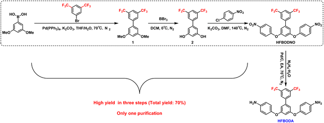
The synthesis procedure of HFBODA is shown in Scheme 1. The obtained HFBODNO was added to a 250 mL three-necked flask and dissolved in EA. Then, Pd/C (10% Pd on carbon, 2.2 g) was added to the flask. The reaction mixture was gradually heated to 70 °C. N2H4·H2O (10 mL) was added dropwise when the reaction began to reflux. The reaction mixture was stirred at this temperature for 3 h. The mixture was then filtered and the solvents were evaporated under vacuum, and the residue was purified using flash column chromatography on silica gel (petroleum ether/ethyl acetate = 10![[thin space (1/6-em)]](https://www.rsc.org/images/entities/char_2009.gif) :
:![[thin space (1/6-em)]](https://www.rsc.org/images/entities/char_2009.gif) 1 to 2
1 to 2![[thin space (1/6-em)]](https://www.rsc.org/images/entities/char_2009.gif) :
:![[thin space (1/6-em)]](https://www.rsc.org/images/entities/char_2009.gif) 1) to give HFBODA (17.5 g, 90% yield) as a light yellow solid. 1H NMR (400 MHz, DMSO-d6) δ 8.21–8.16 (m, 2H), 8.13–8.07 (m, 1H), 7.06–6.93 (d, J = 2.2 Hz, 2H), 6.85–6.76 (m, 4H), 6.62–6.53 (m, 4H), 6.42–6.29 (t, J = 2.2 Hz, 1H), 5.01 (s, 4H). 13C NMR (100 MHz, DMSO-d6) δ 161.13, 146.18, 145.48, 142.64, 140.29, 131.53, 131.20, 128.00, 127.96, 125.05, 122.34, 121.27, 115.31, 109.90, 105.29. HRMS (APCI) m/z: [M + H]+ calculated for C26H18F6O2N2, 505.3318; found, 505.3325.
1) to give HFBODA (17.5 g, 90% yield) as a light yellow solid. 1H NMR (400 MHz, DMSO-d6) δ 8.21–8.16 (m, 2H), 8.13–8.07 (m, 1H), 7.06–6.93 (d, J = 2.2 Hz, 2H), 6.85–6.76 (m, 4H), 6.62–6.53 (m, 4H), 6.42–6.29 (t, J = 2.2 Hz, 1H), 5.01 (s, 4H). 13C NMR (100 MHz, DMSO-d6) δ 161.13, 146.18, 145.48, 142.64, 140.29, 131.53, 131.20, 128.00, 127.96, 125.05, 122.34, 121.27, 115.31, 109.90, 105.29. HRMS (APCI) m/z: [M + H]+ calculated for C26H18F6O2N2, 505.3318; found, 505.3325.
2.3 Synthesis of PAAs
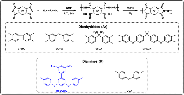
The synthesis of PAA is shown in Scheme 2, taking PAA-BPDA-HFBODA as an example: HFBODA (2.52 g, 5.0 mmol) and 16.0 mL (20 wt%) of NMP were added into a 100 mL three-necked flask, and stirred with a mechanical rod under an N2 atmosphere at room temperature. After HFBODA was completely dissolved, BPDA (0.74 g, 2.5 mmol) was added in two parts. Finally, the reaction mixture was stirred at room temperature for 24 h. After the reaction finished, a centrifuge was used to remove air bubbles in the PAA solution at a speed of 8000 rpm for 10 min.The synthesis method of the remaining PAA was similar to that of PAA-BPDA-HFBODA, the amount of diamine was 5.0 mmol and that of dianhydride was 2.5 mmol × 2, and the solid content of the reaction system was 20 wt%.
2.4 Preparation of PI samples
The transparent PAA solutions were spin coated on 10 × 10 cm clean glass plates, prebaked at 90 °C for 5 min. Next, the samples were placed in a convection oven under an N2 atmosphere, heated to 100 °C at a heating rate of 5 °C min−1, and maintained at the same temperature for 1 h. Then, the temperature was elevated at the same heating rate and maintained at 200 °C for 1 h, 300 °C for 1 h, and 350 °C for 1 h. The samples were peeled from the glass plates in HF aqueous solution, rinsed with ultrapure water, and dried at 100 °C under vacuum to obtain the final PI films.3 Results and discussion
3.1 Synthesis and characterization
The diamine was synthesized via a conventional procedure, as shown in Scheme 1. Firstly, the fluorinated aromatic ring was connected by the Suzuki reaction, which was followed by acid mediated deprotection reaction to obtain the diphenol intermediate. Then, the dinitro intermediate HFBODNO was obtained by nucleophilic aromatic substitution reaction of the diphenol intermediate with 4-chloronitrobenzene. Finally, the novel diamine HFBODA was produced from HFBODNO by a hydrogenation reaction. The 1H NMR and 13C NMR spectra of HFBODNO are presented in Fig. S1a and S1b.† The chemical structure of HFBODA was characterized by 1H NMR and 13C NMR spectra shown in Fig. S2a and S2b.† Additionally, the HRMS and HPLC spectra of HFBODA are summarized in Fig. S3a and S3b.†The molecular weights of the synthesized PAAs were characterized using GPC. The detailed results are shown in Table 1. The results showed that HFBODA had good reactivity with various common dianhydrides, and the Mw values of PIs based on HFBODA were in the range of 25![[thin space (1/6-em)]](https://www.rsc.org/images/entities/char_2009.gif) 090–28
090–28![[thin space (1/6-em)]](https://www.rsc.org/images/entities/char_2009.gif) 983.
983.
| Samples | GPC | WXRD | |||
|---|---|---|---|---|---|
| M n (g mol−1) | M w (g mol−1) | PDIa | 2θ (°) | d spacing (Å) | |
| a PDI = Mw/Mn. | |||||
| BPDA-HFBODA | 15![[thin space (1/6-em)]](https://www.rsc.org/images/entities/char_2009.gif) 762 762 |
27![[thin space (1/6-em)]](https://www.rsc.org/images/entities/char_2009.gif) 742 742 |
1.76 | 16.30 | 5.44 |
| ODPA-HFBODA | 14![[thin space (1/6-em)]](https://www.rsc.org/images/entities/char_2009.gif) 452 452 |
27![[thin space (1/6-em)]](https://www.rsc.org/images/entities/char_2009.gif) 155 155 |
1.88 | 15.81 | 5.61 |
| 6FDA-HFBODA | 13![[thin space (1/6-em)]](https://www.rsc.org/images/entities/char_2009.gif) 043 043 |
25![[thin space (1/6-em)]](https://www.rsc.org/images/entities/char_2009.gif) 090 090 |
1.92 | 15.83 | 5.60 |
| BPADA-HFBODA | 14![[thin space (1/6-em)]](https://www.rsc.org/images/entities/char_2009.gif) 043 043 |
28![[thin space (1/6-em)]](https://www.rsc.org/images/entities/char_2009.gif) 983 983 |
2.06 | 15.76 | 5.62 |
| BPDA-ODA | 16![[thin space (1/6-em)]](https://www.rsc.org/images/entities/char_2009.gif) 703 703 |
33![[thin space (1/6-em)]](https://www.rsc.org/images/entities/char_2009.gif) 991 991 |
2.04 | 17.33 | 5.12 |
| ODPA-ODA | 16![[thin space (1/6-em)]](https://www.rsc.org/images/entities/char_2009.gif) 052 052 |
29![[thin space (1/6-em)]](https://www.rsc.org/images/entities/char_2009.gif) 443 443 |
1.83 | 17.99 | 4.93 |
| 6FDA-ODA | 14![[thin space (1/6-em)]](https://www.rsc.org/images/entities/char_2009.gif) 043 043 |
27![[thin space (1/6-em)]](https://www.rsc.org/images/entities/char_2009.gif) 510 510 |
1.96 | 16.10 | 5.50 |
| BPADA-ODA | 14![[thin space (1/6-em)]](https://www.rsc.org/images/entities/char_2009.gif) 595 595 |
28![[thin space (1/6-em)]](https://www.rsc.org/images/entities/char_2009.gif) 494 494 |
1.95 | 15.80 | 5.61 |
The structures of PIs based on HFBODA were characterized by FT-IR, and the corresponding FT-IR spectra are shown in Fig. 1a and Fig. S4a.† The peaks observed at 1780 cm−1 and 1720 cm−1 were attributed to the asymmetric and symmetric stretching of the C![[double bond, length as m-dash]](https://www.rsc.org/images/entities/char_e001.gif) O bond, respectively. The presence of the C–N bond was demonstrated by the peak at 1380 cm−1 and the peak at 720 cm−1 was assigned to the bending vibration of the C
O bond, respectively. The presence of the C–N bond was demonstrated by the peak at 1380 cm−1 and the peak at 720 cm−1 was assigned to the bending vibration of the C![[double bond, length as m-dash]](https://www.rsc.org/images/entities/char_e001.gif) O bond. The characteristic peak representing the –CF3 group of HFBODA was observed at 1275 cm−1. Besides, the FT-IR spectra of the control systems with the traditional diamine ODA are shown in Fig. S4b,† and the characteristic peaks of PIs were similarly observed, providing evidence of the successful synthesis of PIs. Furthermore, the structures of the synthesized PIs were characterized by wide-angle X-ray diffraction (WXRD). In Fig. 1b and Fig. S4c,† no sharp diffraction peaks are observed, demonstrating that the PI films have amorphous structures. Based on Bragg's law (2d
O bond. The characteristic peak representing the –CF3 group of HFBODA was observed at 1275 cm−1. Besides, the FT-IR spectra of the control systems with the traditional diamine ODA are shown in Fig. S4b,† and the characteristic peaks of PIs were similarly observed, providing evidence of the successful synthesis of PIs. Furthermore, the structures of the synthesized PIs were characterized by wide-angle X-ray diffraction (WXRD). In Fig. 1b and Fig. S4c,† no sharp diffraction peaks are observed, demonstrating that the PI films have amorphous structures. Based on Bragg's law (2d![[thin space (1/6-em)]](https://www.rsc.org/images/entities/char_2009.gif) sin
sin![[thin space (1/6-em)]](https://www.rsc.org/images/entities/char_2009.gif) θ = nλ), the dspacing values were calculated, and are listed in Table 1. It can be intuitively seen that the HFBODA group exhibits larger dspacing values than the ODA group. These increased free volumes provide favorable conditions for enhanced dielectric performance, thus contributing to the better dielectric properties observed in the HFBODA-based PIs.
θ = nλ), the dspacing values were calculated, and are listed in Table 1. It can be intuitively seen that the HFBODA group exhibits larger dspacing values than the ODA group. These increased free volumes provide favorable conditions for enhanced dielectric performance, thus contributing to the better dielectric properties observed in the HFBODA-based PIs.
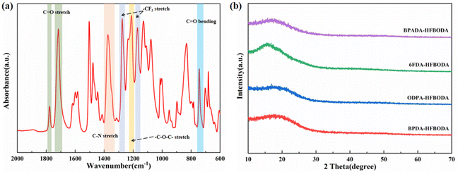 | ||
| Fig. 1 Structural characterization of PI films. (a) FT-IR spectrum of BPADA-HFBODA and (b) WXRD patterns of the HFBODA groups. | ||
3.2 Thermal and mechanical properties
The thermal stability of PIs was an important criterion for practical application in FOWLP. The thermal decomposition temperatures at 5% and 10% weight loss (Td,5% and Td,10%) as well as the residual weight at 800 °C (R800) of the synthesized PIs were determined using TGA, and are presented in Fig. 2a, with the values listed in Table 2. The Td,5% and Td,10% of the HFBODA group were in the range of 495–533 °C and 518–564 °C, respectively. Besides, the PIs based on HFBODA still have more than 50% char yield even at 800 °C, indicating superior thermal stability compared with the ODA groups, as summarized in Fig. S5a† and Table 2. Among the HFBODA based PIs, BPDA-HFBODA exhibits the highest Td,5% value of 533 °C, likely attributed to its higher benzene ring proportion. Interestingly, 6FDA-HFBODA shows a higher Td,5% value than ODPA-HFBODA and BPADA-HFBODA, but a lower Td,10% value than ODPA-HFBODA, which might be attributed to the gradual decomposition of the trifluoromethyl groups in the molecular chain of 6FDA-HFBODA. As a result, 6FDA-HFBODA had the lowest R800 value among HFBODA based PIs. The glass transition temperature (Tg) of the samples was detected using DSC, and the corresponding curves are shown in Fig. 2b and Fig. S5b.† The presence of rotatable single bonds such as ether bonds in HFBODA would result in lower Tg values. Therefore, the Tg values of HFBODA based PIs were in the range of 197–240 °C, and 6FDA-HFBODA exhibited the highest Tg value among them. Fig. 2c shows the dimensional stability of the synthesized PI films, and it could be seen that the coefficient of thermal expansion (CTE) values of the HFBODA groups are slightly higher than that of the control group (as shown in Fig. S5c†). The increase in the CTE values is generally attributed to the bulky bis(trifluoromethyl) pendant group, which might disturb the ordered orientation of the molecular chain, thereby reducing intermolecular interactions and the efficiency of polymer chain packing. | ||
| Fig. 2 Thermal properties of the HFBODA groups. (a) TGA curves of the HFBODA groups, (b) DSC curves of the HFBODA groups and (c) TMA curves of the HFBODA groups. | ||
| Samples | Thermal properties | Mechanical properties | ||||||
|---|---|---|---|---|---|---|---|---|
| TGA | DSC | TMAa | DMA | |||||
| T d,5% [°C] | T d,10% [°C] | R 800 [%] | T g [°C] | CTE [ppm K−1] | σ max [MPa] | ε b [%] | E [GPa] | |
| a Temperature range: 50–180 °C. | ||||||||
| BPDA-HFBODA | 533 | 564 | 58.5 | 237 | 66 | 123.03 ± 5.14 | 9.84 ± 1.16 | 2.85 ± 0.28 |
| ODPA-HFBODA | 510 | 548 | 55.7 | 219 | 77 | 102.80 ± 4.57 | 7.38 ± 1.63 | 2.61 ± 0.23 |
| 6FDA-HFBODA | 521 | 541 | 52.2 | 240 | 76 | 96.64 ± 7.19 | 9.16 ± 0.68 | 2.16 ± 0.37 |
| BPADA-HFBODA | 495 | 518 | 53.4 | 197 | 90 | 115.88 ± 13.97 | 8.56 ± 1.31 | 2.78 ± 0.28 |
| BPDA-ODA | 522 | 558 | 57.1 | 285 | 49 | 118.36 ± 4.79 | 10.04 ± 0.95 | 2.75 ± 0.17 |
| ODPA-ODA | 475 | 531 | 49.8 | 267 | 60 | 98.70 ± 3.30 | 13.71 ± 0.71 | 2.06 ± 0.16 |
| 6FDA-ODA | 510 | 534 | 53.2 | 285 | 66 | 81.69 ± 7.11 | 11.75 ± 0.22 | 1.99 ± 0.20 |
| BPADA-ODA | 459 | 481 | 45.6 | 215 | 61 | 93.59 ± 2.01 | 5.78 ± 0.68 | 2.71 ± 0.17 |
When functioning as an interlayer dielectric material in RDL, PI was required to provide a stress buffer to protect the chip from damage. Therefore, it was crucial to explore the mechanical properties of the synthesized PIs, and the typical stress–strain curves are presented in Fig. 3 and Fig. S6.† It could be observed that the HFBODA groups exhibit remarkable mechanical properties, with the maximum tensile strength (σmax), the elongation at the break (εb) and Young's modulus (E) falling in the range of 96.64–123.03 MPa, 7.38–9.84% and 2.16–2.85 GPa, respectively. In particular, BPDA-HFBODA had the best mechanical properties among the HFBODA-based PIs, which is attributed to the rigid backbone structure of BPDA. 6FDA-HFBODA had lower εb and E values, which could be explained by more trifluoromethyl groups, resulting in decreased intermolecular forces.
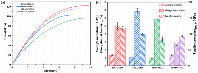 | ||
| Fig. 3 Mechanical properties of the HFBODA groups. (a) Typical stress–strain curves of the HFBODA groups and (b) column chart of the mechanical parameters of the HFBODA groups. | ||
3.3 Dielectric properties
The dielectric properties of the PI films at high frequency (10 GHz) were systematically investigated, and the results are shown in Fig. 4 and summarized in Table 3. Notably, the Dk values of PIs in the HFBODA group are consistently lower than those of the corresponding control group as shown in Fig. 4a. The PI film of 6FDA-HFBODA with the highest fluorine content has the lowest Dk value (2.63 @ 10 GHz). This observation indicates a clear correlation between the Dk values of the PIs and their fluorine content. The fluorine atom with a small atomic radius and concentrated negative charge tightly attracts the charge and results in low electron and atomic polarization. Furthermore, the Dk values of the synthesized PIs are consistent with the dspacing values presented in Table 1. The –CF3 groups in the side chain of PIs could facilitate an increased free volume, which further contributes to the overall reduction in Dk values.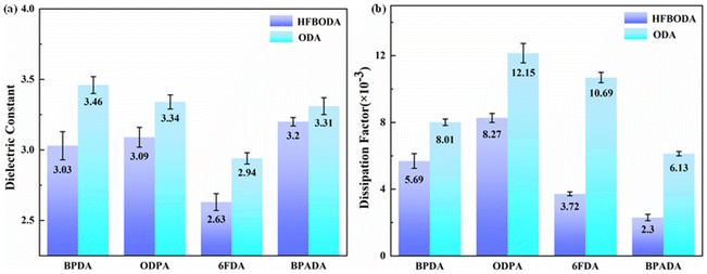 | ||
| Fig. 4 (a) Dielectric constants of the synthesized PIs at 10 GHz and (b) dissipation factors of the synthesized PIs at 10 GHz. | ||
| Samples | Dielectric propertiesa | Hydrophilicity | Optical properties | |||
|---|---|---|---|---|---|---|
| D k | D f (×10−3) | WA (%) | WCA (°) |
λ
cut![[thin space (1/6-em)]](https://www.rsc.org/images/entities/char_2009.gif) (nm)
(nm) |
Transmittancec (%) | |
| a 10 GHz at room temperature. b λ cut: cutoff wavelength. c Transmittance at 500 nm. | ||||||
| BPDA-HFBODA | 3.03 ± 0.10 | 5.69 ± 0.44 | 0.30 | 83.1 | 351.5 | 79.4 |
| ODPA-HFBODA | 3.09 ± 0.07 | 8.27 ± 0.27 | 0.15 | 79.1 | 352.0 | 82.8 |
| 6FDA-HFBODA | 2.63 ± 0.06 | 3.72 ± 0.12 | 0.10 | 86.6 | 336.0 | 84.8 |
| BPADA-HFBODA | 3.20 ± 0.03 | 2.30 ± 0.19 | 0.17 | 98.9 | 351.0 | 85.0 |
| BPDA-ODA | 3.46 ± 0.06 | 8.01 ± 0.19 | 1.91 | 68.1 | 408.5 | 78.2 |
| ODPA-ODA | 3.34 ± 0.05 | 12.15 ± 0.58 | 0.87 | 64.5 | 375.5 | 81.3 |
| 6FDA-ODA | 2.94 ± 0.04 | 10.69 ± 0.31 | 0.49 | 66.9 | 363.0 | 83.1 |
| BPADA-ODA | 3.31 ± 0.06 | 6.13 ± 0.13 | 4.43 | 61.3 | 355.5 | 59.1 |
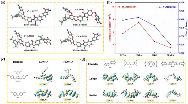
To date, there have been few ways to reduce Df at high frequencies by synthesizing novel polyimides while simultaneously maintaining low Dk. At high frequencies, the polar imide ring in PI could cause the orientation speed of the dipole within the molecule to lag behind the change rate of the electric field, resulting in a dissipation factor.31,33 Therefore, in order to effectively reduce Df and balance the dielectric properties of PI, a new strategy using the side bis(trifluoromethyl) group was proposed in this work. It was clear that the Df values of the HFBODA group were lower than those of the corresponding control group. The incorporation of the side bis(trifluoromethyl) group played a vital role in reducing the charge density of the imide groups in the polyimide backbone by its strong electron-withdrawing ability, thereby leading to lower Df values at high frequencies. The relationships between the Df values and structures of the synthesized PIs were further verified via theoretical calculations, as shown in Fig. 5. The charge density (C) of the imide rings of the synthesized PIs was calculated by natural bond orbital (NBO) analysis. The correlation between the dissipation factors of the PIs and the charge density of the imide rings is shown in Fig. 5a and Fig. S7.† It was not difficult to find that the calculation results were consistent with the experimental results, and the tendency of the Df values was in line with the charge density of the imide ring in Fig. 5b, which proved the effectiveness of the calculation methods. Specifically, 6FDA-HFBODA had a lower Df value (3.72 × 10⁻³ @ 10 GHz) due to a lower charge density (C = 0.38043e), and BPADA-HFBODA exhibited the lowest Df value (2.30 × 10⁻³ @ 10 GHz), attributed to the lowest charge density (C = 0.32509e) of the imide ring. To explore the effect of monomer structures on the Df of PI, the lowest unoccupied molecular orbital (LUMO) and the highest occupied molecular orbital (HOMO) of monomers were calculated, and are shown in Fig. 5c and d. The LUMO of ODA was distributed at the benzene ring adjacent to the amino group, while the LUMO of HFBODA was mainly distributed at the side group, which further proved the electron-withdrawing effect of the bis(trifluoromethyl) side group in HFBODA. In addition, as shown in Table S1,† the dissipation factor values of HFBODA based PI films were significantly lower than those of previously reported PIs, which was attributed to the rational and novel structure design of the bis(trifluoromethyl) side group. In conclusion, these results successfully demonstrated the effectiveness of incorporating an electron-withdrawing rigid side group to lower the dissipation factor of PIs, offering valuable insights for the development of advanced materials with optimized dielectric properties.
3.4 Water absorption and hydrophilicity
It is necessary to explore the water absorption (WA) of PI films in order to achieve permanent application in advanced packaging. The WA results of the PI films are shown in Fig. 6a and Table 3. The WA values of the HFBODA groups are in the range of 0.10%–0.30%, while those of the control groups are in the range of 0.49%–1.91%, which indicates that the HFBODA groups have better hydrophobicity than the control groups. The enhanced hydrophobicity could be attributed to the high electronegativity of fluorine (4.0), resulting in high energy of the C–F bond. Therefore, it was difficult for fluorine atoms to act as electron donors to form hydrogen bonds with water molecules, leading to reduced water absorption. Moreover, 6FDA-HFBODA showed the lowest WA (0.10%) among all the samples. The water contact angle (WCA) of the PI films was also systematically investigated, and the results are shown in Fig. 6b and Table 3. The WCA values of the HFBODA groups were in the range of 79.1°–98.9°, while those of the control groups ranged from 61.3° to 68.1°. BPADA-HFBODA showed the highest WCA values (98.9°) among all the samples. In summary, the excellent hydrophobic properties of the synthesized PIs make them promising candidates for long-term reliability applications in advanced packaging technologies.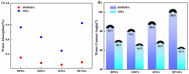 | ||
| Fig. 6 (a) Water absorption of the synthesized PIs and (b) water contact angle of the synthesized PIs. | ||
3.5 Optical properties
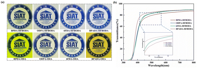
In general, the color of PIs reflects the strength of the intramolecular and intermolecular charge transfer complex (CTC). Photographs of the synthesized PI films are shown in Fig. 7a, and the HFBODA based PI films show better visible optical transparency than the control PI films. In order to further explore the optical properties, UV-vis spectroscopy was used to characterize the transmittance, and the details are shown in Fig. 7b, Fig. S8† and Table 3. As shown in Table 3, the cut-off wavelength (λcut) and transmittance at 500 nm of the HFBODA based PI films are in the range of 336.6–352.0 nm and 79.4–85.0%, respectively. For the control groups, the cut-off wavelength (λcut) and transmittance at 500 nm were in the range of 355.5–408.5 nm and 59.1–83.1%, respectively. Obviously, the HFBODA groups have lower λcut and higher transmittance at 500 nm than the control groups due to the strong electron-withdrawing effect of the trifluoromethyl group.13,36,37 Besides, the larger volume of the bis(trifluoromethyl) and isopropylidene groups would cause a larger steric hindrance, hindering the intermolecular CTC. As a result, 6FDA-HFBODA and BPADA-HFBODA exhibited good optical transparency. The excellent optical performance of the HFBODA based PIs could embrace more application scenarios, including display fields, optical devices, and other optical applications.3.6 Solubility
The PI applied in FOWLP needed to have enhanced solution-processability in view of numerous procedures in packaging. Therefore, the solubility of these PI films was qualitatively investigated, and the results are listed in Table 4. Obviously, the HFBODA groups have better solubility than the control groups, which is attributed to the fluorine element of HFBODA enhancing its affinity for the solvent and reducing the intermolecular force. Besides, the steric effect of the pendant group of HFBODA distorted the polymer chain, thereby destroying the conjugation effect and hindering the intramolecular charge transfer. Consequently, the solubility of the PI films with HFBODA in polar aprotic solvents such as NMP, DMF, DMAc, DMSO, THF, TCM, and DCM was significantly increased. Notably, BPADA-HFBODA exhibited the best solubility among all the samples, which might be attributed to its loose molecular chain arrangement and the presence of more flexible groups, including the ether bond and isopropylidene group. The special structure facilitated a higher level of interaction with solvents and the molecular chain of BPADA-HFBODA, leading to enhanced solubility and making BPADA-HFBODA a promising candidate for application in the microelectronics field.| Samples | NMP | DMF | DMAc | DMSO | THF | TCM | DCM |
|---|---|---|---|---|---|---|---|
| Testing method: 5 mg of PI films dissolved in 8 mL of solvent. ++soluble at room temperature for 24 h; +soluble at 60 °C for 24 h; −insoluble at 60 °C for 24 h. | |||||||
| BPDA-HFBODA | + | − | − | − | − | − | − |
| ODPA-HFBODA | + | − | − | − | − | − | − |
| 6FDA-HFBODA | ++ | ++ | + | ++ | ++ | + | − |
| BPADA-HFBODA | ++ | ++ | ++ | ++ | ++ | ++ | + |
| BPDA-ODA | − | − | − | − | − | − | − |
| ODPA-ODA | − | − | − | − | − | − | − |
| 6FDA-ODA | − | − | − | − | − | − | − |
| BPADA-ODA | − | − | − | − | − | − | − |
4 Conclusions
A novel fluorine-containing diamine monomer was successfully synthesized and polymerized with commonly available dianhydrides to prepare PI films with notably low Dk and Df values. The HFBODA based PI films presented excellent dielectric properties at a high frequency of 10 GHz, alongside desirable hydrophobicity and optical properties, as well as superior solubility and thermal stability. In particular, 6FDA-HFBODA had the most balanced properties among the synthesized PIs (Td,5% = 521 °C, Tg = 240 °C, WA = 0.49%, Dk = 2.63 and Df = 3.72 × 10⁻³ @ 10 GHz). Additionally, BPADA-HFBODA showcased an ultra-low Df value (2.30 × 10⁻³ @ 10 GHz), owing to the lower charge density of the main chain. The strategy of decreasing the charge density of the imide groups by introducing strong electron-withdrawing groups into the side group of PIs, which could effectively achieve a low dissipation factor at high frequencies, was further validated by theoretical calculations. Overall, this work has provided some valuable theoretical guidance and technical pathways for the design of novel PIs with exceptional dielectric properties, specifically tailored for high-frequency applications. Our findings opened up new possibilities for advanced electronic and communication technologies, offering significant potential for future developments in the field.Author contributions
Yao Zhang: conceptualization, methodology, validation, formal analysis, visualization, and writing—original draft. Shan Huang: validation, investigation, data curation, and writing—review and editing. Xialei Lv: formal analysis, writing—review and editing, and funding acquisition. Kuangyu Wang: methodology. Huimin Yin: investigation. Siyao Qiu: software. Jinhui Li: supervision, project administration, and funding acquisition. Guoping Zhang: project administration and funding acquisition. Rong Sun: project administration.Conflicts of interest
There are no conflicts to declare.Acknowledgements
The authors acknowledge the financial support from Guangdong Jointed Funding, 2020A1515110934, and the National Natural Science Foundation of China (61904191). We are also thankful for the experiment platform of SIAT CAS-CUHK Joint Laboratory of Materials and Devices for High Density Electronic Packaging and the Guangdong Provincial Key Laboratory of High Density Electronic Packaging Key Materials (2014B030301014).References
- S. Zhang, X. Xu, T. Lin and P. He, J. Mater. Sci.: Mater. Electron., 2019, 15(30), 13855–13868 CrossRef.
- Y. Su, K. Chiang and S. Liang, J. Mech., 2017, 2(33), 193–203 CrossRef.
- J. Lau, IEEE Trans. Compon., Packag., Manuf. Technol., 2022, 2(12), 228–252 Search PubMed.
- T. Braun, K. Becker, O. Hoelck, S. Voges, R. Kahle and M. Dreissigacker, Micromachines, 2019, 10(5), 342 CrossRef PubMed.
- L. Wang, C. Liu, S. Shen, M. Xu and X. Liu, Ind. Eng. Chem. Res., 2020, 3(4), 138–148 Search PubMed.
- J. Luo, Y. Wu, Y. Sun, G. Wang, Y. Liu and X. Zhao, Appl. Sci., 2019, 9(9), 1962 CrossRef CAS.
- I. Tseng, P. Hsu, W. Hsu, D. Tran, B. Lin and C. Chang, Results Phys., 2021, 31, 105048 CrossRef.
- C. Liang, Y. Lin, C. Kao, D. Tarng, S. Wang and Y. Hung, Mater. Chem. Phys., 2020, 256, 123680 CrossRef CAS.
- Y. Ding, H. Duan, M. Xie, R. Mao, J. Wang and W. Zhang, Resour., Conserv. Recycl., 2022, 182, 106339 CrossRef CAS.
- S. Misra and G. Panwar, IEEE Wirel. Commun., 2017, 24(1), 4–5 Search PubMed.
- G. Maier, Prog. Polym. Sci., 2001, 26(1), 3–65 CrossRef CAS.
- Y. Watanabe, Y. Shibasaki, S. Ando and M. Ueda, Polym. J., 2006, 38(1), 79–84 CrossRef CAS.
- H. T. Zuo, F. Gan, J. Dong, P. Zhang, X. Zhao and Q. H. Zhang, Chin. J. Polym. Sci., 2021, 39(4), 455–464 CrossRef CAS.
- C. Yang, J. Dong, Y. Fang, L. Ma, X. Zhao and Q. Zhang, J. Mater. Chem. C, 2018, 6, 1229–1238 RSC.
- S. H. Hsiao and Y. H. Chang, J. Polym. Sci., Part A: Polym. Chem., 2004, 42(5), 1255–1271 CrossRef CAS.
- C. Y. Wang, W. T. Chen, Y. Y. Chen, X. Y. Zhao, J. Li and Q. Ren, Mater. Chem. Phys., 2014, 143, 773–778 CrossRef CAS.
- T. Wu, J. Dong, F. Gan, Y. Fang, X. Zhao and Q. Zhang, Appl. Surf. Sci., 2018, 440, 595–605 CrossRef CAS.
- C. Ding, R. Li, J. Yu, X. Wang and P. Huang, J. Mater. Sci., 2022, 57, 9480–9492 CrossRef CAS.
- Z. Liu, L. Pang, Q. Li, S. Zhang, J. Li and H. Tong, High Perform. Polym., 2018, 30(4), 446–455 CrossRef CAS.
- P. Lv, Z. Dong, X. Dai and X. Qiu, J. Appl. Polym. Sci., 2019, 136(14), 47313 CrossRef.
- P. Lv, Z. Dong, X. Dai and X. Qiu, ACS Appl. Polym. Mater., 2019, 1(10), 2597–2605 CrossRef CAS.
- Y. Ma, L. Xu, Z. He, J. Xie, L. Shi and M. Zhang, J. Mater. Chem. C, 2019, 7(24), 7360–7370 RSC.
- J. Ju, Q. Wang, T. Wang and C. Wang, Colloid Interface Sci. Commun., 2013, 404, 36–41 CrossRef CAS PubMed.
- W. Chen, Z. Zhou, T. Yang, R. Bei, Y. Zhang and S. Liu, React. Funct. Polym., 2016, 108, 71–77 CrossRef CAS.
- M. Zhong, X. Wu, C. Shu, Y. Wang, X. Huang and W. Huang, React. Funct. Polym., 2021, 169, 105065 CrossRef CAS.
- H. Zheng, C. Wang, Z. Tao, C. Jiang, X. Zhao and J. Li, J. Electron. Mater., 2021, 50(12), 6981–6990 CrossRef CAS.
- Y. Wu, Z. Chen, J. Ji, Y. Zhou, H. Huang and S. Liu, Eur. Polym. J., 2020, 132, 109742 CrossRef CAS.
- R. Bei, C. Qian, Y. Zhang, Z. Chi, S. Liu and X. Chen, J. Mater. Chem. C, 2017, 5(48), 12807–12815 RSC.
- Y. Liu, C. Qian, L. Qu and Y. Wu, Chem. Mater., 2015, 27(19), 6543–6549 CrossRef CAS.
- S. Bong, H. Yeo, B. Ku, M. Goh and N. H. You, Macromol. Res., 2017, 26(1), 85–91 CrossRef.
- C. Y. Wang, H. P. Zhao, G. Li and J. M. Jiang, Polym. Adv. Technol., 2011, 22(12), 1816–1823 CrossRef CAS.
- H. Araki, Y. Kiuchi, A. Shimada, H. Ogasawara, M. Jukei and M. Tomikawa, J. Photopolym. Sci. Technol., 2020, 33(2), 165–170 CrossRef CAS.
- J. He, H. Yang, F. Zheng and S. Yang, Polymers, 2022, 14(3), 649 CrossRef CAS PubMed.
- Q. Yin, Y. Qin, J. Lv, X. Wang, L. Luo and X. Liu, Ind. Eng. Chem. Res., 2022, 61(49), 17894–17903 CrossRef CAS.
- C. Kuo, Y. Lin, Y. Chen, P. Wu, S. Ando and M. Ueda, ACS Appl. Polym. Mater., 2020, 3(1), 362–371 CrossRef.
- Y. Wang, X. Liu, J. Shen, J. Zhao and G. Tu, Polymers, 2022, 14(19), 4132 CrossRef CAS PubMed.
- H. Min, B. Kang, Y. Shin, B. Kim, S. Lee and J. H. Cho, ACS Appl. Mater. Interfaces, 2020, 12(16), 18739–18747 CrossRef CAS PubMed.
Footnotes |
| † Electronic supplementary information (ESI) available. See DOI: https://doi.org/10.1039/d3py00773a |
| ‡ These authors contributed equally to this work. |
| This journal is © The Royal Society of Chemistry 2023 |

