 Open Access Article
Surface modification and adhesive-free adhesion of polytetrafluoroethylene (PTFE) and silicone gel containing oleophilic SiO2 powder by plasma treatment†
Erika Miyakea,
Misa Nishinoa,
Yosuke Setoa,
Izuru Komatsub,
Katsuyoshi Endoa,
Kazuya Yamamuraa and
Yuji Ohkubo *a
*a
aGraduate School of Engineering, Osaka University, 2-1 Yamadaoka, Suita, Osaka 565-0871, Japan. E-mail: okubo@upst.eng.osaka-u.ac.jp
bToshiba Corporate Manufacturing Engineering Center, 33 Shin-Isogo-cho, Isogo-ku, Yokohama 235-0017, Japan
First published on 9th January 2023
Abstract
Polytetrafluoroethylene (PTFE) has high-frequency characteristics and low transmission loss, and is expected to be used as a substrate material of printed wiring board for high-frequency applications. Meanwhile, silicone gel has superior properties such as attaching/detaching, weather resistance, and human safety. If the PTFE and silicone gel can be strongly adhered to, they can be applied to internet of things (IoT) devices that can be attached and detached freely. However, adhesion between PTFE, which has poor adhesion, and silicone gel, which has low mechanical strength, is difficult and has not been reported. In this study, PTFE was modified with heat-assisted plasma treatment, and silicone gel was treated with oleophilic SiO2 powder to improve elastic modulus and modified with plasma jet treatment, and then bonded without adhesive. The adhesion strength of PTFE/silicone gel assembly was 1.13 N mm−1 when treated moderately, but only 0.01 N mm−1 when untreated and treated excessively. To investigate the factors causing the difference in the adhesion strength, the surface of silicone gel was evaluated by water contact angle measurement, Fourier transform infrared spectroscopy, and confocal laser scanning microscopy. When treated moderately, hydrophilic functional groups and cross-linking were most frequently increased. Furthermore, when treated excessively, surface degradation was observed, which was expected to lower the adhesion strength. The adhesive-free bonding between PTFE and silicone gel can open a new path for developing IoT devices that can be freely attached and detached.
1 Introduction
Internet of things (IoT) devices are installed in wearable devices, home appliances, and buildings as a means to improve productivity and safety through real-time detection of operational status and anomalies. With the development of electronic information technology, IoT devices are expected to transmit and receive larger amounts of data at higher speeds in the future. Increase in frequency is required to increase the transmission data amount. However, the transmission loss increases with increasing the frequency. To decrease the transmission loss, the resin substrate having low relative dielectric constant (Dk) and dielectric loss tangent (Df) must be used because transmission loss depends on Dk and Df. Therefore, fluorine-based resin with the lowest Dk and Df must be used as the resin substrate. Polytetrafluoroethylene (PTFE) has an extremely low dielectric constant and dielectric loss tangent among fluoropolymers, as well as excellent chemical resistance, weather resistance, and heat resistance, it is expected to be applied as a printed wiring board materials that can suppress transmission loss in high-frequency bands.1 Currently, IoT devices are generally installed and used at specific locations, and no products allow the user to freely change the installation location. Therefore, if IoT devices compatible with high-frequency bands and detachability, it will be possible to use them depending on the situation and purpose. To fabricate such devices, a technology is required to strongly bond PTFE, which has excellent high-frequency characteristics, and gel material, which has excellent detachability.Regarding the adhesion of gel materials to adherents, ionogel, hydrogel, and organogel have been reported so far. It has been reported that the shear strength of ionogel and adherents (PTFE, Al, glass, wood, PP, PE, PVC, and steel) is 0.36–3.2 MPa, which is relatively high even without surface modification.2,3 This is explained by the various polar functional groups present on the surface of the ionogel that contributed to its adhesive properties.4 However, only low values of 0.08–0.12 N mm−1 were obtained for peel strength with adherents (glass, VHB, Cu, copolymer).5 Considering that the peel strength between a resin substrate and metal wiring is specified as 0.98 N mm−1 in the JPCA standard for printed wiring board materials, there is a concern that the application as an electronic substrate material using ionogel may be limited because it may cause damage, large deformation, or even rupture in environments where peel strength is required. Furthermore, while ionogel has excellent mechanical properties, self-adhesiveness, and conductivity,4 a problem has been reported that the hygroscopic property of ionic liquids (ILs) causes hydrolysis under high humidity conditions.5 There is also the problem of IL leakage during compression, making long-term use difficult.5 Ionogel is prepared by mixing the polymer matrix and ILs, and drying them in UV irradiation or vacuum oven. However, the number of processes is a lot and it takes many days to fabricate.2,3 Regarding the adhesion strength of hydrogel to other materials, it has been reported that the peel strength of polyacrylamides (PAAm) gel to acrylic elastomer due to its low self-adhesion property is <0.01 N mm−1, which is low peel strength.6 Silane-modified hydrogel can also be bonded to silicone elastomers via covalent bonds, but the peel strength has been reported to be <0.1 N mm−1.7 The peel strength of poly(acrylic acid) hydrogel and PAAm was <0.2 N mm−1,8 and the peel strength between PAAm gel and adherents (PAAm gel,9 glass, silicone elastomer, Al2O3 (ref. 10)) using topological adhesion technology was <0.35 N mm−1, and low peel strength has been reported in all cases. No papers investigate the peel strength between hydrogel and PTFE. Hydrogel has excellent flexibility, hydrous properties, ionic conductivity, and biocompatibility, so it is used in biomedical fields such as artificial skin, strain sensors, and soft robots.11–13 Hydrogel such as double network gel and triblock copolymer gel have high mechanical strength, shape retention, and high modulus,14–16 but the number of processes is a lot and takes several days to complete. However, polyacrylamides (PAAm) gel and alginate gel are relatively inexpensive and require fewer steps to fabricate, but have the disadvantages of low mechanical strength and limited use environment due to shape changes caused by drying.17 Finally, few reports have investigated the adhesion properties of organogels. An example of the lesser of these is silicone gel. It has been reported that surface modification of silicone gel by plasma or UV treatment improves the surface energy and elastic modulus, and that hydrophilic functional groups containing oxygen are introduced, making it easier to adsorb metal sputtering films (Au, Ag, Ti), but the specific peeling strength has not been reported.18 Furthermore, there are no papers investigating adhesion to PTFE. However, when polydimethylpolysiloxane (PDMS) rubber, which has siloxane bonds like silicone gel, is treated with plasma, the peel strength to the adherent (Cu, glass, PTFE) is >2.0 N mm−1, which is a strong adhesion without adhesive.19 One possible reason for the improved peel strength is that the hydrophobic methyl groups (CH3) on the PDMS rubber surface were replaced by hydrophilic functional groups (Si–OH) containing oxygen by the plasma treatment. Therefore, silicone gel, which has a chemical structure similar to that of PDMS rubber, is likely to have improved adhesion with plasma treatment. Additionally, silicone gel has long been applied in various fields, including micro-patterned substrates20 and vibration and shock absorbers,21 due to its superior removability, shape stability, and safety and hygiene. Furthermore, silicone gel has the advantage of requiring fewer materials and processes because it can be easily molded by filling it with one-component or two-component precursor of silicone gel and then heating or UV irradiation it. In this study, silicone gel was used as the gel material, and the surface of the silicone gel was modified by plasma treatment to achieve strong adhesive-free bonding based on chemical interaction with plasma-treated PTFE. The surface-modification conditions and adhesion properties for different cases of ionogel, hydrogel, and organogel are listed in Table 1.
| Gel | Surface modification for gel | Adherend | Surface modification for adherend | Intermediate | Adhesion strength | Ref. |
|---|---|---|---|---|---|---|
| a VHB: very high bondtape.b MEA: methyl ether acrylate.c IBA: isobornyl acrylate.d PAAm: polyacrylamides.e Chitosan solution: 4-morpholineethanesulfonic acid. | ||||||
| Ionogel I | No | PTFE | No | No | 0.4 MPa | 2 |
| Ionogel I | No | Al | No | No | 0.4 MPa | 2 |
| Ionogel I | No | Glass | No | No | 0.4 MPa | 2 |
| Ionogel I | No | Wood | No | No | 1.0 MPa | 2 |
| Ionogel II | No | PTFE | No | No | 1.0 MPa | 3 |
| Ionogel II | No | PP | No | No | 1.2 MPa | 3 |
| Ionogel II | No | PE | No | No | 1.5 MPa | 3 |
| Ionogel II | No | PVC | No | No | 2.8 MPa | 3 |
| Ionogel II | No | Steel | No | No | 3.2 MPa | 3 |
| Ionogel III | No | Glass | No | No | 0.12 N mm−1 | 5 |
| Ionogel III | No | VHBa | No | No | 0.11 N mm−1 | 5 |
| Ionogel III | No | Cu | No | No | 0.08 N mm−1 | 5 |
| Ionogel III | No | Copolymer (MEAb-co-IBAc) | No | No | 0.08 N mm−1 | 5 |
| Hydrogel (PAAmd) | No | Acrylic elastomer | No | No | <0.01 N mm−1 | 6 |
| Hydrogel (silane-modified) | No | PDMS elastomer | No | No | <0.1 N mm−1 | 7 |
| Hydrogel (poly (acrylic)acid) | No | PAAm | No | No | <0.2 N mm−1 | 8 |
| Hydrogel (PAAm) | No | Hydrogel (PAAm) | No | Yes (chitosan solutione) | 0.15 N mm−1 | 9 |
| Hydrogel (PAAm) | No | Glass | No | Yes (PAA, NalO4) | 0.35 N mm−1 | 10 |
| Hydrogel (PAAm) | No | PDMS | No | Yes (PAA, NalO4) | 0.27 N mm−1 | 10 |
| Hydrogel (PAAm) | No | Al2O3 | No | Yes (PAA, NalO4) | 0.33 N mm−1 | 10 |
| Organogel (silicone gel) | Yes (UV irradiation) | Au, Ag, Ti | No | No | No data | 18 |
| Organogel (silicone gel) | Yes (O2 plasma treatment) | Au, Ag, Ti | No | No | No data | 18 |
| Organogel (silicone gel) | Yes (N2 + air plasma treatment) | PTFE | Heat-assisted plasma | No | 1.13 N mm−1 | This study |
2 Material and methods
2.1 Preparation of silicone gel
In this experiment, one-component heat-cure silicone gel (KE1062, Shin-Etsu Chemical) was used as a precursor of silicone gel. The structural formula of silicone gel precursor is shown in Fig. 1. Oleophilic SiO2 powder (SS-30P, Tosoh Silica) or hydrophilic SiO2 powder (VN3, Tosoh Silica) was added to improve the mechanical strength of the silicone gel. Oleophilic SiO2 powder was considered to have affinity with silicone gel which is a kind of organogel because the silanol group (Si–OH) is replaced by a methyl group (CH3) on the SiO2 surface. For comparison, hydrophilic SiO2 powder was also used. First, a silicone gel precursor and hydrophilic or oleophilic SiO2 powder were add to a polypropylene cup of 500 mL (MonotaRO) and stirred for 1 min using a hand mixer (D-1123 hand mixer miracles, Pearl Metal). Next, the uncrosslinked silicone gel containing SiO2 powder was poured into a heat-resistant glass mold and cured at 120 °C for 30 min in a vacuum dryer (AVO-200NS, AS-ONE). The thickness of the crosslinked silicone gel was 13 mm, because the adhesion strength depended on the gel thickness (ESI-1†) when cohesion failure of the silicone gel occurred. Table 2 shows the list of silicone gel prepared in this study.| Sample name | KE1062 [g] | SS-30P [g] | VN3 [g] |
|---|---|---|---|
| a SG20: 20 g of silicone gel precursor (KE1062).b SG20-OP3: 20 g of KE1062 + 3 g of oleophilic SiO2 powder (SS-30P).c SG20-OP5: 20 g of KE1062 + 5 g of oleophilic SiO2 powder (SS-30P).d SG20-HP5: 20 g of KE1062 + 5 g of hydrophilic SiO2 powder (VN3). | |||
| SG20a | 20 | 0 | 0 |
| SG20-OP3b | 20 | 3 | 0 |
| SG20-OP5c | 20 | 5 | 0 |
| SG20-HP5d | 20 | 0 | 5 |
2.2 Sample preparation by plasma treatment
Plasma treatment was performed on the crosslinked silicone gel using an open-air-type plasma jet (PJ) treatment equipment (Tough Plasma FPE-20, FUJI) according to previous report19 for a silicone rubber. The number of scans during the PJ treatment was set to 0, 2, 20, and 60 times, and the effects of the number of scans on surface properties of silicone gel were compared.2.3 Preparation of PTFE/silicone gel assembly
As an adhered to silicone gel, a plasma-treated PTFE sheet (NITOFLON® No. 900UL, Nitto Denko; thickness: 0.2 mm) was used. It is well-known that conventional plasma treatment at low temperature do not improve adhesion property of PTFE because PTFE has a weak boundary layer (WBL).22 Therefore, a heat-assisted plasma (HAP) treatment was adopted according to previous report19 because the HAP treatment improves drastically adhesion property of PTFE. During HAP treatment, the surface temperature of the PTFE sheet was measured with a digital radiation thermometer (FT-H40K and FT-50A, Keyence), and it was confirmed that the maximum surface temperature was over 200 °C. In order to confirm that the HAP treatment was performed properly, the wettability of the HAP-treated PTFE was evaluated by water contact angle (WCA), its surface chemical composition was analyzed by X-ray photoelectron spectroscopy (XPS), and its surface morphology was observed by scanning electron microscope (SEM). The WCA decreased from 123 to 87° by HAP treatment, which indicates that the wettability improved. XPS analysis confirmed that after HAP treatment, oxygen-containing functional groups were added, including O–C![[double bond, length as m-dash]](https://www.rsc.org/images/entities/char_e001.gif) O, C
O, C![[double bond, length as m-dash]](https://www.rsc.org/images/entities/char_e001.gif) O, and –C–O– groups as shown in ESI-2.† SEM images showed that the number and size of voids on the PTFE surface after HAP treatment were reduced and smoothed, confirming that the WBL22 on the PTFE surface was removed, as shown in ESI-3.† The HAP-treated PTFE was placed on the PJ-treated silicone gel in a mold such that the plasma-treated surfaces faced each other, then the PTFE/silicone gel assembly was compressed at 140 °C and 12.5 MPa for 10 min using a hot-pressing machine (AH-2003, AS-ONE) without using any adhesives.
O, and –C–O– groups as shown in ESI-2.† SEM images showed that the number and size of voids on the PTFE surface after HAP treatment were reduced and smoothed, confirming that the WBL22 on the PTFE surface was removed, as shown in ESI-3.† The HAP-treated PTFE was placed on the PJ-treated silicone gel in a mold such that the plasma-treated surfaces faced each other, then the PTFE/silicone gel assembly was compressed at 140 °C and 12.5 MPa for 10 min using a hot-pressing machine (AH-2003, AS-ONE) without using any adhesives.
2.4 Methods
| E* = E′ + iE′′ | (1) |
We calculated E* 11 times at each frequency and defined the average of 11 values as the E*. Also, we defined the error as maximum value of difference between mean value and measured value.
![[thin space (1/6-em)]](https://www.rsc.org/images/entities/char_2009.gif) :
:![[thin space (1/6-em)]](https://www.rsc.org/images/entities/char_2009.gif) 1 mass ratio because the viscosity of the silicone gel itself needed to be as low as possible. After a drop of silicone gel precursor with low viscosity was placed on the mirror-finished Al plate, spin coating was performed for 30 s at a rotational speed of 6000 rpm, and then the Al plate coated with the diluted silicone gel were cured in an a vacuum dryer (AVO-200NS, AS-ONE) at 120 °C for 30 min. FTIR spectra were collected at 3800–3000 cm−1 for Si–OH group, 3000–2900 cm−1 for CH3 group, and 1050–950 cm−1 for cross-linked Si–O–Si group, respectively.
1 mass ratio because the viscosity of the silicone gel itself needed to be as low as possible. After a drop of silicone gel precursor with low viscosity was placed on the mirror-finished Al plate, spin coating was performed for 30 s at a rotational speed of 6000 rpm, and then the Al plate coated with the diluted silicone gel were cured in an a vacuum dryer (AVO-200NS, AS-ONE) at 120 °C for 30 min. FTIR spectra were collected at 3800–3000 cm−1 for Si–OH group, 3000–2900 cm−1 for CH3 group, and 1050–950 cm−1 for cross-linked Si–O–Si group, respectively.3 Results and discussion
3.1 Viscoelasticity measurement of silicone gel after addition of oleophilic SiO2 powder
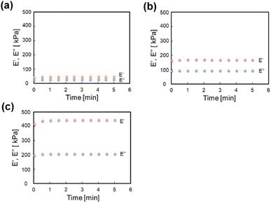
Fig. 2 shows the change over time of the storage modulus (E′) and loss modulus (E′′) of SG20, SG20-OP3, and SG20-OP5. It was found that as the amount of oleophilic SiO2 powder added increased, both the storage modulus and loss modulus increased. The complex modulus of elasticity (E*) of SG20, SG20-OP3, and SG20-OP5 was 54 ± 6 kPa, 189 ± 4 kPa, and 484 ± 26 kPa, indicating that the stress required to deform the material increases. These results indicate that silicone gels with high viscosity and mechanical strength can be made by adding oleophilic SiO2 powder to silicone gel precursor.3.2 Adhesion strength measurements of PTFE/silicone gel assemblies
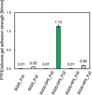
The adhesion strength was compared between PTFE/SG20-OP5 and PTFE/SG20-HP5 assemblies. For a comparison, the adhesion strength of PTFE/SG20 having no SiO2 powder was measured. The effect of PJ treatment on adhesion was also investigated. Fig. 3 shows the adhesion strength of PTFE/silicone gel assemblies with or without PJ treatment for silicone gel.When the silicone gel was not PJ-treated, the adhesion strength was 0.01 N mm−1 in all cases, and the HAP-treatment PTFE sheets were easily peeled off from the silicone gel by hand. In contrast, when the silicone gel was PJ-treated, the adhesion strength increased in all cases, and the highest results obtained when oleophilic SiO2 powder was added. The addition of oleophilic SiO2 powder improved mechanical property of the silicone gel, resulting in suppression of breaking the silicone gel in the T-peel test. ESI-4 and 5† show videos of the T-peel test of PTFE/SG20-OP5-PJ0 and PTFE/SG20-OP5-PJ2.
ESI-6† is a video of attachment/detachment test of the PTFE/silicone gel assembly to confirm the possibility of repeated use. In the test, the attachment and detachment were repeated more than 10 times to the Al substrate (HA0513, Hikari). In all cases, the silicone gel adhered to the Al substrate, and we confirmed that the PTFE/silicone gel interface and silicone gel itself were not broken. The results show that PTFE/silicone gel assembly has both adhesive and durability properties.
Additionally, Fig. 4 shows the adhesion strength of PTFE/SG20-OP5 assembly with the different number of PJ scans. The highest adhesion strength was obtained when the number of PJ scans was two times. In contrast, when the number of PJ scans was 0 or 60 times, the adhesion strength was 0.01 N mm−1. These results indicate that the number of PJ scans to the silicone gel plays a significant role in the adhesion strength of PTFE/silicone gel assembly.
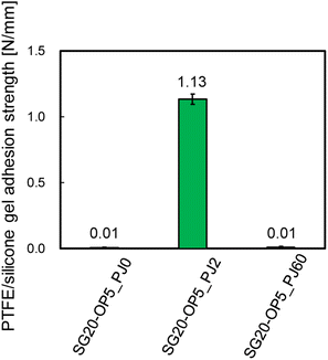 | ||
| Fig. 4 PTFE/silicone gel adhesion strength of PTFE/SG20-OP5 assembly with the different number of PJ scans. | ||
3.3 Chemical factor of improvement in adhesion strength
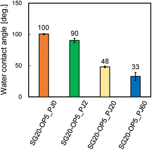
From Fig. 4, there is clear that there is a significant correlation between the number of PJ scans and adhesion strength. To investigate the relation between the wettability of the silicone gel surface and the number of PJ scans, the WCA was measured. The results of the WCA measurements are shown in Fig. 5. When the number of PJ scans increased, the WCA decreased, and a hydrophilic surface was obtained. Generally, the higher the wettability of the surface is, the higher the adhesion property for adherents is. However, the WCA results were inconsistent with the results of the adhesion strength in Fig. 4.To investigate the effect of PJ treatment on chemical bonding state of silicone gel, FTIR-RAS measurements were also performed. ESI-7† shows FTIR-RAS spectra of silicone gel containing oleophilic SiO2 powder. Since noise makes it difficult to analyze the spectra of silicone gel, PJ treatment and FTIR-RAS measurement were performed for silicone gel non-containing oleophilic SiO2 powder as shown in Fig. 6. At the bands at 3800–3000 cm−1, two main significant peaks were observed. The one peak at the highest wavenumber side (3747 cm−1) is attributed to an isolated Si–OH group. The other broad peak at 3500–3200 cm−1 is attributed to water molecules. The highest absorbance attributed to the Si–OH group was detected in the case of two scans of PJ treatment, and the percentage of Si–OH group decreased in the case of 60 scans. At the bands at 3000–2900 cm−1, the peaks attributed to the side chain methyl groups were observed, and the absorbance decreased via PJ treatment. This is thought to be because the methyl group of Si–CH3 is cleaved by PJ treatment and replaced with a cross-linked Si–O–Si group or a hydrophilic functional group Si–OH group. At 1050–950 cm−1, the peak attributed to asymmetric Si–O–Si stretching vibrations of chain siloxanes were observed. When the number of PJ scans was two, the peak absorbance of the Si–O–Si group increased significantly, which indicates frequent occurrence of cross-links between silicone chains. This is thought to be because the PJ treatment cleaved the methyl groups and replaced them with Si–O–Si crosslinks. In contrast, when the number of PJ scans was 60 s, Si–O–Si groups increased by a certain amount, but the rate of increase was lower than in the case of 2 scans. This is thought to be due to the cleavage of the Si–O– Si crosslinks generated by the excessive plasma treatment. These results show the same trend as the adhesion strength result of PTFE/SG20-OP5 assembly shown in Fig. 4.
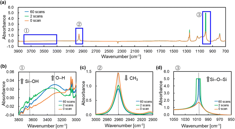 | ||
| Fig. 6 FTIR-RAS spectra of silicone gel non-containing oleophilic SiO2 powder with the different number of PJ scans (a) 3900–700 cm−1, (b) 3800–3000 cm−1, (c) 3000–2900 cm−1, and (d) 1050–950 cm−1. | ||
3.4 Physical factor of improvement in adhesion strength
Fig. 7 shows CLSM images of silicone gel with and without oleophilic SiO2 powder. In Fig. 7(a), the surface of SG20 non-containing oleophilic SiO2 powder was flat. In contrast, in Fig. 7(b), it was found that the addition of oleophilic SiO2 powder to silicone gel formed an overall uneven structure and increased the surface roughness. This unevenness would be caused by both dispersion and aggregation of the SiO2 particles with each other (average diameter 8.9 μm) in the silicone gel. Fig. 8 shows the CLSM images of SG20-OP5 with the different number of PJ scans of 0, 2, and 60 times. No significant difference in surface morphology was observed when the number of PJ scans was 0 or 2, but many cracks were observed on the surface only when the number of PJ scans was 60 s. These are cracks indicate the formation of a new WBL on the silicone gel surface by excessive plasma treatment. These results are also consistent with the results of the adhesion strength of the PTFE/SG20-OP5 assembly, as shown in Fig. 4. Considering the results of adhesion strength, WCA, FTIR-RAS, and CLSM comprehensively, it was found that chemical factors such as surface wettability and the amount of hydrophilic functional groups were more dominant than physical factors as factors contributing to the adhesion strength of PTFE/silicone gel assembly. In addition to this, it became clear that higher adhesion strength could be obtained by increasing the mechanical strength of the silicone gel itself on the premise that the interface is strongly bonded.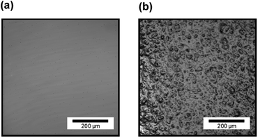 | ||
| Fig. 7 CLSM images of silicone gel (a) without oleophilic powder (SG20) and (b) with oleophilic SiO2 powder (SG20-OP5). | ||
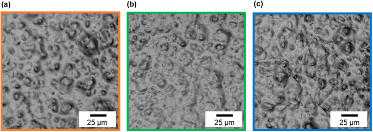 | ||
| Fig. 8 CLSM images of silicone gel containing oleophilic SiO2 powder (SG20-OP5) with the different number of PJ scans (a) 0 scan, (b) 2 scans, and (c) 60 scans. | ||
4 Conclusions
In this study, oleophilic SiO2 powder was added to the silicone gel to improve its mechanical strength, and PJ treatment was applied to achieve strong adhesion between the silicone gel and PTFE without using any adhesive. By applying moderate PJ treatment (2 scans) to the silicone gel, the highest adhesion strength of 1.13 N mm−1 was obtained. However, untreated (0 scan) or excessive PJ treatment (60 scans) resulted in a low value of 0.01 N mm−1. Therefore, we investigated the reasons for the difference in adhesion strength between the moderately PJ-treated case and untreated, excessively PJ-treated cases. First, the WCA of the silicone gel surface in the moderately PJ-treated case was 90°, which was 10° lower than that in the untreated case. Analysis of the chemical bonding before and after PJ treatment using FTIR-RAS spectra showed a decrease in the methyl groups (CH3) in the side chains of siloxane bonds and an increase in the hydrophilic functional groups (Si–OH) and cross-links between silicone chains (Si–O–Si). Therefore, strong adhesion was achieved by formation of chemical bonding when the plasma-treated PTFE surface and the silicone gel surface containing hydrophilic functional groups from PJ treatment touched each other. Next, the untreated surface of the silicone gel exhibited a WCA of 100°, indicating that the surface was hydrophobic. Furthermore, in the FTIR-RAS spectra, the spectral intensities of hydrophilic functional groups (Si–OH) and cross-links (Si–O–Si) were observed to be much lower in the moderately and excessively PJ-treated. Therefore, it is expected that chemical bonds were not formed with the PTFE surface, resulting in lower adhesion strength. Finally, in the excessively PJ-treated case, the WCA was 33°, indicating a highly-hydrophilic surface. The FTIR-RAS spectra showed an increase in the spectral intensity of hydrophilic functional groups (Si–OH) and cross-links (Si–O–Si), but the intensity was lower than that in the moderately PJ-treated case. Furthermore, no cracks were observed in the CLSM images at 0 and 2 scans, but some cracks were observed on the surface at excessive treatment (60 scans), indicating that a WBL was formed on the surface due to the excessive surface modification. Therefore, it is concluded that although a higher hydrophilic surface can be obtained by excessive PJ treatment, strong adhesion to PTFE is impossible due to the lower number of functional groups and cross-links formed and the surface degradation. These results indicate that it is important to perform moderate plasma treatment to increase the number of hydrophilic functional groups and cross-linked structures to improve the adhesion properties of silicone gel. Adhesive-free adhesion between PTFE having the superior high-frequency properties and silicone gel having attachment/detachment property may provide a clue to the development of beyond 5G IoT devices that can be attached and detached according to purpose and situation of use.Author contributions
Y. O., I. K., K. E. and K. Y. supervised the work. E. M. prepared silicone gel and performed plasma treatments and prepared the plasma-treated PTFE and silicone gel samples. Y. S. and M. N. performed the viscoelasticity measurement, adhesion strength measurement, WCA measures, FTIR measurements and CLSM observation. All authors contributed to the scientific discussion and manuscript preparation. E. M. wrote the manuscript. All authors have read and agreed to the published version of the manuscript.Conflicts of interest
The authors declare no conflict of interest.Acknowledgements
Oleophilic SiO2 powder (SS-30P) and hydrophilic SiO2 powder (VN3) were provided by Tosoh Silica Corporation; we thank them for their assistance. The FTIR measurements were performed at the Analytical Instrument Facility, Graduate School of Science, Osaka University. This work was supported by staffs at the Analytical Instrument Facility, Graduate School of Science, Osaka University. We thank to Mr Kawamura who is the member of the Analytical Instrument Facility, Graduate School of Science, Osaka University, for the discussion about FTIR-RAS data.Notes and references
- A. J. Bur, Polymer, 1985, 26, 963–977 CrossRef CAS.
- J. Zhu, X. Lu, W. Zhang and X. Liu, Macromol. Rapid Commun., 2020, 41, 2000098 CrossRef CAS.
- S. Huang, Y. Wan, X. Ming, J. Zhou, M. Zhou, H. Chen, Q. Zhang and S. Zhu, ACS Appl. Mater. Interfaces, 2021, 13, 41112–41119 CrossRef.
- S. Xiang, F. Zheng, S. Chen and Q. Lu, ACS Appl. Mater. Interfaces, 2021, 13, 20653–20661 CrossRef CAS.
- B. Yiming, X. Guo, N. Ali, N. Zhang, X. Zhang, Z. Han, Y. Lu, Z. Wu, X. Fan, Z. Jia and S. Qu, Adv. Funct. Mater., 2021, 31, 2102773 CrossRef.
- J. Tang, J. Li, J. J. Vlassak and Z. Suo, Soft Mater., 2016, 12, 1093 RSC.
- Q. Liu, G. Nian, C. Yang, S. Qu and Z. Suo, Nat. Commun., 2018, 9, 846 CrossRef PubMed.
- Y. Wang, K. Jia, C. Xiang, J. Yang, X. Yao and Z. Suo, ACS Appl. Mater. Interfaces, 2019, 11, 40749–40757 CrossRef PubMed.
- J. Yang, R. Bai and Z. Suo, Adv. Mater., 2018, 30, 1800671 CrossRef.
- Y. Gao, J. Chen, X. Han, Y. Pan, P. Wang, T. Wang and T. Lu, Adv. Funct. Mater., 2020, 30, 2003207 CrossRef.
- E. M. Ahmed, J. Adv. Res., 2015, 2, 105–121 CrossRef.
- C. Yang and Z. Suo, Nat. Rev. Mater., 2018, 3, 125–142 CrossRef.
- Y. Cheng, K. H. Chan, X.-Q. Wang, T. Ding, T. Li, X. Lu and G. W. Ho, ACS Nano, 2019, 13, 13176–13184 CrossRef.
- J. P. Gong, Y. Katsuyama, T. Kurokawa and Y. Osada, Adv. Mater., 2003, 15, 1155–1158 CrossRef.
- Q. Wang, J. L. Mynar, M. Yoshida, E. Lee, M. Lee, K. Okuro, K. Kinbara and T. Aida, Nature, 2010, 463, 339–343 CrossRef PubMed.
- H. J. Zhang, T. L. Sun, A. K. Zhang, Y. Ikura, T. Nakajima, T. Nonoyama, T. Kurokawa, O. Ito, H. Ishitobi and J. P. Gong, Adv. Mater., 2016, 28, 4884–4890 CrossRef PubMed.
- Y. Zhuo, J. Chen, S. Xiao, T. Li, F. Wang, J. He and Z. Zhang, Mater. Horiz., 2021, 12, 3266–3280 RSC.
- M. Franke, I. Slowik, E. Langer, K. Leo and A. Richter, Surf. Interface Anal., 2020, 52, 1163–1170 CrossRef.
- Y. Ohkubo, K. Endo and K. Yamamura, Sci. Rep., 2018, 8, 18058 CrossRef.
- E. Gutierrez and A. Groisman, PLoS One, 2011, 6, e25534 CrossRef.
- Sutisno and A. P. Adi, J. Mechatron. Electr. Power Veh. Technol., 2012, 3, 111–116 CrossRef.
- Y. Seto, M. Nishino, Y. Okazaki, K. Endo, K. Yamamura and Y. Ohkubo, Polym. J., 2022, 54, 79–81 CrossRef.
Footnote |
| † Electronic supplementary information (ESI) available. See DOI: https://doi.org/10.1039/d2ra05749b |
| This journal is © The Royal Society of Chemistry 2023 |


