 Open Access Article
Exploring MOF-199 composites as redox-active materials for hybrid battery-supercapacitor devices
Muhammad Zahir Iqbal *a,
Misbah Shaheena,
Muhammad Waqas Khana,
Salma Siddiqueb,
Sikandar Aftab
 c,
Saikh Mohammad Wabaidurd and
Muhammad Javaid Iqbale
aFaculty of Engineering Sciences, Ghulam Ishaq Khan Institute of Engineering Sciences and Technology, Topi 23640, Khyber Pakhtunkhwa, Pakistan. E-mail: zahir@giki.edu.pk
bFaculty of Allied Health Sciences and Technology, Women University Swabi, Topi 23640, Khyber Pakhtunkhwa, Pakistan
cDepartment of Intelligent Mechatronics Engineering, Sejong University, 209 Neungdong-ro, Gwangjin-gu, Seoul 05006, South Korea
dChemistry Department, College of Science, King Saud University, Riyadh 11451, Saudi Arabia
eCentre of Excellence in Solid State Physics, University of the Punjab, Quaid-e-Azam Campus, Lahore, 54590, Punjab, Pakistan
First published on 18th January 2023
Abstract
Metal–organic frameworks (MOFs) have emerged as intriguing porous materials with diverse potential applications. Herein, we synthesized a copper-based MOF (MOF-199) and investigated its use in energy storage applications. Methods were adapted to intensify the electrochemical characteristics of MOF-199 by preparing composites with graphene and polyaniline (PANI). The specific capacity of the synthesized MOF in a three-electrode assembly was significantly enhanced from 88 C g−1 to 475 C g−1 and 766 C g−1 with the addition of graphene and polyaniline (PANI), respectively. Due to the superior performance of (MOF-199)/PANI, a hybrid supercapacitor was fabricated with the structure of (MOF-199)/PANI//activated carbon, which displayed an excellent maximum energy and power density of 64 W h kg−1 and 7200 W kg−1, respectively. The hybrid device exhibited an appreciable capacity retention of 92% after 1000 charge–discharge cycles. Moreover, using Dunn's model, the capacitive and diffusive contributions as well as the k1 and k2 currents of the fabricated device were calculated, validating the hybrid nature of the supercapattery device. The current studies showed that MOF-199 exhibits promising electrochemical features and can be considered as potential electrode material for hybrid energy storage devices.
1. Introduction
The increasing demand for electronics has led to an increase in the demand for energy storage devices (ESDs). Also, the detrimental effects of fossil fuel and its depletion has prompted the development of renewable energy resources and ESDs.1 Eminently, batteries and supercapacitors (SCs) are the flagship ESDs for the majority of energy storage applications.2 Energy density (Es) and power density (Ps) are indispensable factors that establish the importance of an energy storage device. In this regard, batteries deliver an appropriate Es originating from redox reactions but cannot meet high Ps demands.3 Hence, supercapacitors are appropriate to enhance Ps but are limited by their low Es. However, despite this limiting feature, SCs are capable of rapid charge–discharge with high cyclic stability, making them superior to other ESDs.4 Therefore, numerous investigations have been focused on the enhancement of the Es of SCs without affecting their Ps. Hence, the aforementioned features of batteries and supercapacitors have led to the idea of developing highly efficient devices that combine the features of a battery and SC in a single energy storage system, namely, a ‘supercapattery’. Supercapatteries operate by employing highly efficient battery-grade electrode materials as positive and carbonaceous materials as negative electrode materials. This type of assembly overcomes the barriers of low cyclic stability, low rate-performance and slow kinetics.5,6Predominantly, carbonaceous materials are employed as electric double layer capacitor (EDLC) electrodes due to their low cost, high surface area to volume ratio and high electrical conductivity. In carbon-based materials, charges are stored at the interface of the electrolyte and electrode by physical adsorption, resulting in a long cyclic life and Ps.7 Alternatively, battery-grade materials are dominated by redox oxidation/reduction reactions, which prompt high rate capability and primarily high Es.8 However, investigations are required to search for novel battery-grade materials for next-generation energy storage systems.
Metal–organic frameworks (MOFs) are a novel configuration of metal ions (Cu, Fe, Zn, etc.) and organic ligands (BTC, PTA, DHTA, etc.).9 MOFs are being applied in diverse research fields including catalysis, energy storage devices, and fluorescence, considering their fascinating characteristics such as high specific area, tunable porosity, unique pore structure and rapid diffusion of electrolytic ions.10–16 Recently, MOFs have been directly integrated as electrode materials in energy storage devices including hybrid supercapacitors.17 For example, Shin et al. reported the performance of the Ni-MOF@carbon nanofiber (CNF) for supercapacitor application.18 They achieved a specific capacitance of 742.2 F g−1 at a current density of 1 A g−1. A hybrid supercapacitor constructed with the structure of NiO/C@CNF//activated carbon (AC), which displayed an Es and Ps of 58.43 W h Kg−1 and 1947 W kg−1, respectively. Shin et al.18 synthesized hollow-structured Ni/Co-MOFs and used them for supercapacitor applications.19 When Ni/Co-MOF was integrated as an electrode for supercapacitor, it showed a capacitance of 1498 F g−1 at 1 A g−1. Thus, the above-mentioned results demonstrate the admirable performances of MOFs for supercapacitor applications.
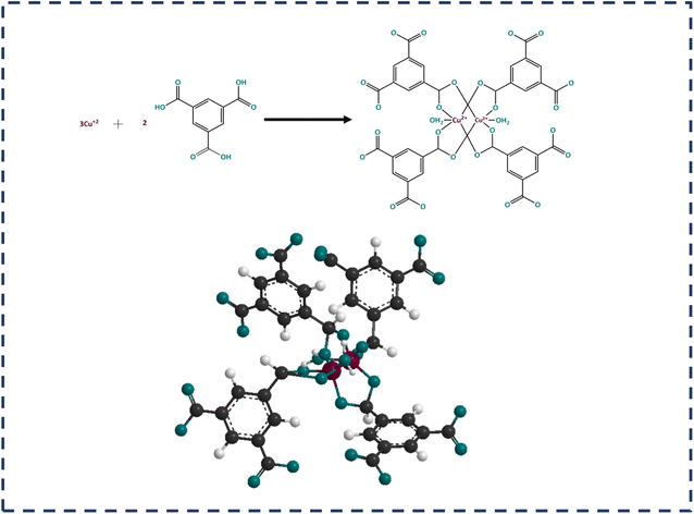
MOF-199 is comprised of paired Cu2+ ions as metal nodes coordinated with four carboxylate groups, which are composed of a benzene-1,3,5-tricarboxylate (BTC) linker. The combination of copper ions with carboxylate groups forms a copper paddle wheel, where a water molecule is attached to the fifth site of the copper ion. The paddle wheel structure is represented in Fig. 1. Different types of conducting polymers (CPs), carbonaceous materials and transition metal-based oxides, phosphates, sulfides, etc., are potential candidates for supercapacitor applications. Given MOF-199 is a comparatively low-conductivity MOF, to utilize its porosity and large surface area, it is usually incorporated with carbon-based materials and CPs to enhance its conductivity.
Graphene is well known to possess several intriguing properties such as high electrical conductivity, large surface-area-to-volume ratio and high mechanical strength.20 Polyaniline (PANI), one of the most well-known conducting polymers, is suitable to enhance the conductivity, electrochemical redox activity and flexibility of composite systems. The high conductivity of PANI is attributed to its emeraldine (fractional oxidized) phase. Hence, by combining graphene/PANI with battery-grade metal oxides, the overall electrochemical performance and stability of the composite can be enhanced significantly. Thus, in electrochemical energy storage devices, graphene/PANI can be utilized to amplify the specific capacity, cyclic stability and rate capability.21–23
Herein, we propose the combination of Cu-based MOF-199 with graphene and polyaniline (PANI). Initially, MOF-199 was synthesized via the hydrothermal method. The obtained material in its pristine form was electrochemically characterized. In the next step, MOF-199/graphene and MOF-199/PANI composites were synthesized and tested in a three-electrode assembly. Moreover, a hybrid-supercapacitor was fabricated by combining the best-performing electrode and activated carbon. To further provide insight into the electrochemical behavior of the as-prepared composite, its structure, elements and surface were characterized.
2. Experimental
2.1. Precursor materials
All precursors used in the synthesis of MOF-199 and slurry preparation including cupric nitrate hemipentahydrate (Cu2H10N4O17), benzene-1,3,5-tricarboxylic acid (BTC linker), 1-methyl-2 pyrrolidinone (NMP), graphene, PANI, polyvinylidene fluoride (PVDF), and carbon black acetylene were purchased from Sigma Aldrich and used without further purification in this reported study. The reference and counter electrodes were procured from ALS Co., Ltd, Japan.2.2. Preparation of electrodes
Three nickel foam samples with an area of 1 × 1.5 cm2 were ultrasonicated in 3 M HCl solution, acetone, ethanol and deionized (DI) water for 10 min, respectively. Then, the washed nickel foam samples were dried at 60 °C in oven before further utilization.2.3. Assembly of supercapattery device
For the asymmetric device, the MOF-199/PANI electrode was placed face-to-face with an activated carbon (AC) electrode. Then, 6 mm-thick nickel foam electrodes were used as the current collector. Both electrodes were separated by a thin filter membrane. For the optimum electrochemical performance of the asymmetric device, charge balancing was carried out using eqn (1).
 | (1) |
![[thin space (1/6-em)]](https://www.rsc.org/images/entities/char_2009.gif) :
:![[thin space (1/6-em)]](https://www.rsc.org/images/entities/char_2009.gif) 2.
2.
2.4. Synthesis of MOF-199
To synthesize porous MOF-199, the hydrothermal method was adapted, as established in the reported methodology.24–26 Briefly, 7 mM cupric nitrate hemipentahydrate (Cu2H10N4O17) was dispersed in 30 mL of DI water. Subsequently, 3.5 mM of BTC linker was mixed in a solution containing two equal portions of ethanol and DI water (30 mL). Both prepared solutions were stirred thoroughly until they were completely dissolved, and then poured into a 100 mL autoclave. The autoclave was kept at a temperature of 130 °C for 24 h in an oven. The autoclave was cooled to ambient temperature and small crystals were obtained. The mixture was centrifuged and blue crystals were isolated. Finally, the acquired material was washed with DI water, acetone, and ethanol several times and dried.2.5. Preparation of MOF-199/graphene and MOF-199/PANI
The working nickel foam electrode of MOF-199/graphene was prepared by making a slurry of 70 wt% of MOF-199, 10 wt% of graphene and carbon black acetylene each, and 10 wt% of PVDF in 2 mL of NMP with stirring for 8 h. The same procedure was followed to prepare MOF-199/PANI expect 10 wt% PANI was added in place of graphene. Then the obtained slurry was loaded in the NF and dried at 60 °C for 6 h.2.6. Electrochemical measurements
Electrochemical characterization was conducted in both three-cell and two-cell assemblies, where 1 M KOH solution was used with the reference and counter electrode of Hg/HgO and platinum wire, respectively. For cyclic voltammetry (CV) and galvanostatic charge discharge (GCD) measurements in the three-electrode setup, the optimum potential window of 0–0.7 V and 0–0.6 V, respectively, was set. For the same measurements in the two-electrode assembly, a potential window of 0–1.6 V was employed for both CV and GCD. The frequency limit for electrochemical impedance spectroscopy (EIS) was set to 0.1 potential window 1.0 MHz.3. Results and discussion
3.1. Structural, morphological, and elemental characterizations
The X-ray diffractograms of the pure MOF-199, MOF-199/graphene and MOF-199/PANI composite are displayed in Fig. 2(a) together with the standard pattern of MOF-199 (JCPDS No. 23-00380). The peaks at 9.4°, 11.7°, 18.8°, 26° and 29.4° confirm the formation of pristine MOF-199, while additional peaks can be observed in the pattern of MOF-199/graphene and MOF-199/PANI. The supplementary peaks correspond to graphene and PANI, confirming the successful incorporation of graphene and PANI in MOF-199. Moreover, the energy dispersive X-ray spectrum of MOF-199 is also displayed in Fig. 2(b), demonstrating the presence of carbon, oxygen and copper elements.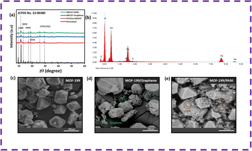 | ||
| Fig. 2 (a) XRD, (b) EDX and (c–e) SEM micrographs of pristine MOF-199, MOF-199/graphene and MOF-199/PANI. | ||
Scanning electron microscopy (SEM) was performed to explore the topology of the pristine MOF-199, MOF-199/graphene and MOF-199/PANI composite. Fig. 2(c) demonstrates that MOF-199 possesses a crystalline structure with the typical octahedral shape morphology, whereas Fig. 3(d and e) validate the successful incorporation of graphene and PANI, respectively. The integration of graphene and PANI with MOF-199 provided a high surface area and more diffusion sites. The average particle size of MOF-199 was calculated to be 30 μm.
3.2. Three-electrode electrochemical results
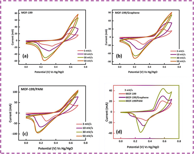
Before fabricating the hybrid device, the as-prepared electrodes (MOF-199, MOF-199/graphene and MOF-199/PANI) were analyzed in a standard three-cell assembly to assess their electrochemical behavior and extract the best-performing sample. Fig. 3(a–c) present the cyclic voltammograms of MOF-199, MOF-199/graphene and MOF-199/PANI, respectively. The appearance of redox peaks in all the samples confirms the occurrence of faradaic reactions. An increase in peak current was observed with an increase in the scan rate. All the samples tended to maintain their CV shapes even with an increase in the scan rate, signifying their good rate capability. A comparison of the CV curves of all three samples at 3 mV s−1 is presented in Fig. 3(d). Interestingly, the incorporation of graphene and PANI in MOF-199 enhanced its redox activity, whereas the main contribution to the peaks originated from the pseudocapacitive nature of MOF-199. The oxidation of the copper ion from Cu1+ to Cu2+ and the reduction from Cu2+ to Cu1+ can clearly observed by the oxidation and reduction peaks located at 0.55 V and 0.35 V in the MOF-199 sample, respectively.The redox peaks also shifted towards lower potential with the inclusion of graphene and PANI, indicating the enhanced electrical conductivity and electrochemical performance of the samples containing graphene and PANI. Moreover, the symmetric nature of the CV curves indicates the reversibility of the redox reactions, making the electrodes highly stable for a long period. The specific capacities of the prepared samples were also calculated using eqn (2).
 | (2) |
![[thin space (1/6-em)]](https://www.rsc.org/images/entities/char_2009.gif) dV is the area under the CV curve, “m” is the active mass and “ν” is the scan rate. The obtained Qs values for MOF-199, MOF-199/graphene and MOF-199/PANI are 451 C g−1, 631 C g−1 and 840 C g−1 at 3 mV s−1, respectively.
dV is the area under the CV curve, “m” is the active mass and “ν” is the scan rate. The obtained Qs values for MOF-199, MOF-199/graphene and MOF-199/PANI are 451 C g−1, 631 C g−1 and 840 C g−1 at 3 mV s−1, respectively.
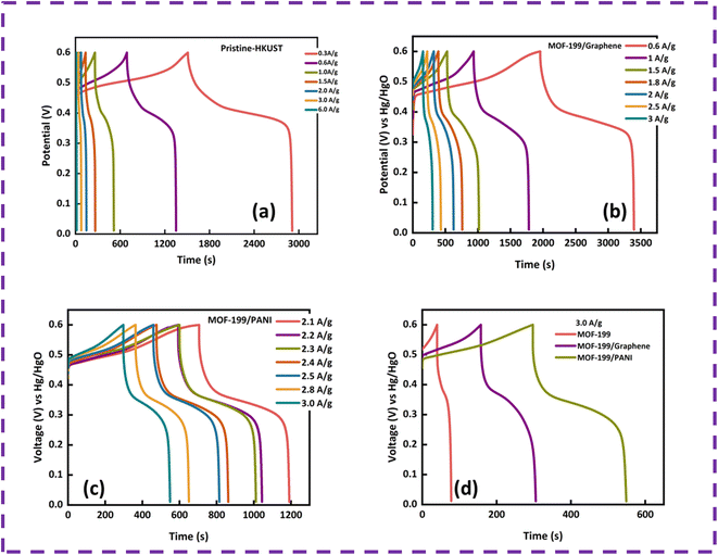
To further analyze the charge storage capability of the prepared electrodes, GCD was performed, and the curves of MOF-199, MOF-199/graphene and MOF-199/PANI are displayed in Fig. 4(a–c), respectively, at various current densities. The plateaus in the GCD curves indicate the pseudocapacitive behavior of all the samples. The shortening of the timescale with an increase in current density is ascribed to the time-dependent movement of the ions present in the electrolyte. The symmetric and stable nonlinear GCD curves at all current densities reveal the good reversibility of all the prepared electrode materials. Fig. 4(d) depicts the GCD curves of the prepared samples at a current density of 3 A g−1. The nonlinear relation of potential with time is in good agreement with the pseudocapacitive part in the CV curves. Moreover, the specific capacity (Qs) values were also calculated using the discharging time of the GCD curves to validate the CV results. Also, Qs was calculated from the GCD results using eqn (3), as follows:
 | (3) |
The Qs values obtained for MOF-199, MOF-199/graphene and MOF-199/PANI using the GCD curves are 88 C g−1, 475 C g−1 and 766 C g−1, respectively.
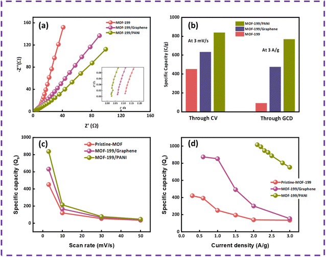
The prepared samples were also tested for their conductive properties, which plays a crucial role in the electrochemical outcomes of the device. The EIS results for MOF-199, MOF-199/graphene and MOF-199/PANI are presented in Fig. 5(a). By comparing the EIS curves, it can be concluded that the absence of a semicircle in the high frequency region indicates that all the prepared electrodes offer insignificant charge transfer resistance (Rct). Alternatively, in the low frequency region, the angled line defines the capacitive or diffusive contribution of the electrodes and the ion diffusion resistance. Pristine MOF-199 has greater capacitive contribution, while MOF-199/PANI has more diffusive contribution and that of MOF-199/graphene lies between both domains. Also, the arcs in the low frequency region display the Warburg impedance, which is lower in the case of MOF-199/PANI given that its length is shorter than the other two samples. Further, a plot showing the comparison of the specific capacities of all the samples obtained from CV and GCD are presented in Fig. 5(b), and Fig. 5(c and d) present the capacities calculated at various scan rates and current densities.
According to the electrochemical analysis, best sample was MOF-199/PANI given that it possesses a large area under the curve in the cyclic voltammograms and it takes a larger time to discharge in the GCD results than other two prepared electrodes. Similarly, MOF-199/PANI exhibited high specific capacity values according to both the CV and GCD results in comparison with the other two electrodes. Additionally, the EIS results also indicated that MOF-199/PANI shows excellent conductive properties, helping ions to diffuse and intercalate easily in the electrode.
3.3. Full cell assembly (asymmetric supercapacitor) electrochemical analysis
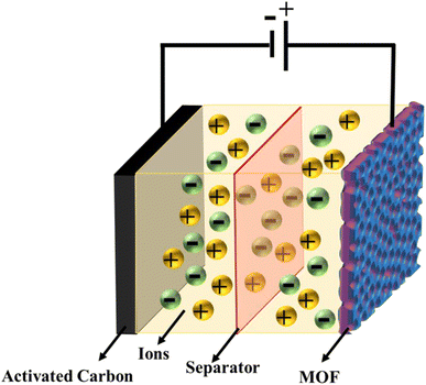
To demonstrate the practical application of MOF-199/PANI, a prototype comprised of activated carbon (AC) and MOF-199/PANI (MOF-199/PANI//AC) with a sandwiched separator layer was fabricated. A schematic of the device is displayed in Fig. 6. An AC was applied at a negative potential, whereas a positive potential was applied to MOF-199/PANI. Given that to achieve the maximum Qs, Es, and Ps, charge balancing is required on both electrodes, thus the charge balance was considered before depositing the mass on the nickel foam electrodes. The charge storage on a single electrode depends upon the deposited mass, capacitance and the potential window, as follows27| q = C × m × Δv | (4) |
Charge balance can be achieved by equalizing the charge on both electrodes, which eventually gives the mass balance equation, as follows (eqn (5)):
 | (5) |
![[thin space (1/6-em)]](https://www.rsc.org/images/entities/char_2009.gif) :
:![[thin space (1/6-em)]](https://www.rsc.org/images/entities/char_2009.gif) 1.6.
1.6.
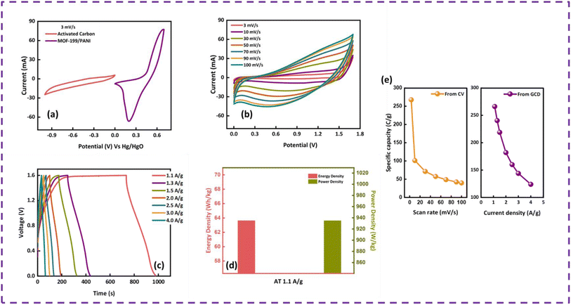
To evaluate the device performance, electrochemical measurements were conducted in a two-cell assembly. The asymmetrically assembled device was tested through CV, GCD and EIS. Fig. 7(a) shows the CV curves of AC and MOF-199/PANI to clearly differentiate between the individual and combined CVs of AC and MOF-199/PANI. It can be observed that the CV of AC indicates the characteristics of conventional EDLC, while the voltammogram of MOF-199/PANI was observed to be a redox-dominant battery-type material. The blended voltammograms of (MOF-199)/PANI//AC in Fig. 7(b) reveal that the total specific capacity of the asymmetric supercapacitor MOF-199/PANI//AC originated from the synergistic effect of the redox reaction of MOF-199/PANI and electrostatically stored charge (AC). Further, the symmetric and distortion-free curves reflect the reversibility and high-rate capability of the device. The insertion of electrolytic ions in the MOF-199 network initiates the reaction between Cu2+ and the electrolyte, which increases the peak current values with an increase in scan rate. Fig. 7(c) shows the GCD plots of the MOF-199/PANI//AC device at seven distinct current densities. The nonlinearity in the GCD results is consistent with the redox peaks positions of the CV curves, indicating its pseudocapacitive nature. The specific capacity of the fabricated hybrid supercapacitor was found to be 535 C g−1 at 3 mV s−1 according to the CV results and 272 C g−1 via GCD at 1.1 A g−1. Further, the Es and Ps values of the hybrid device were calculated using eqn (6). and (7), as follows:28
 | (6) |
 | (7) |
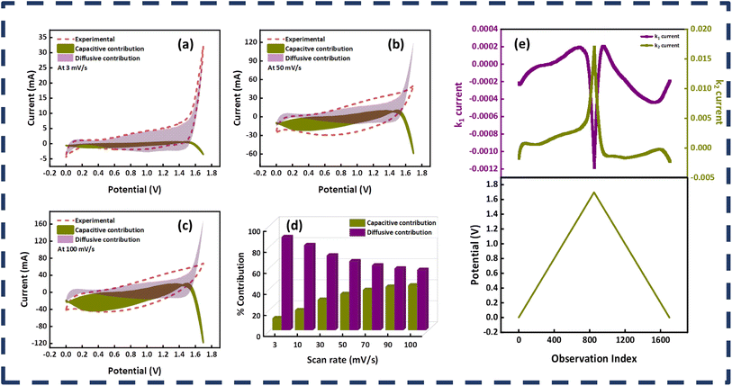
The fabricated device achieved a maximum Es of 64 W h kg−1 and Ps of 7200 W kg−1 at 1.1 A g−1 and 9.0 A g−1, respectively, as displayed in Fig. 7(d). To evaluate the device for its capacitive and diffusive contributions, its b-value was determined using the power law, as follows:29
| i = aνb | (8) |
The impedance spectroscopy results of the MOF-199/PANI//AC device before and after the stability test are presented in Fig. 8(c). The precise point of intersection on the abscissa in the high frequency zone can be used to calculate the equivalent series resistance (ESR), which reveals information about the resistance between the electrode and electrolyte. The ESR value of the MOF-199/PANI//AC device decreased after the stability test, which indicates that it is conductive and serves as evidence of its excellent performance, as demonstrated by the prior electrochemical results. The RCT (charge transfer resistance), which is indicated by the emergence of a semicircle in the high frequency region of the EIS plot, indicates the resistance provided to the electrolytic ions during their transfer to the electrode material. Due to the absence of a semicircle in the case of MOF-199/PANI//AC, this material is very conductive. The lower frequency zones that produce an angled line indicate the presence of Warburg impedance, which controls the diffusion path into the electrode material. In the case of MOF-199/PANI//AC, rapid ion transfer occurs as a result of the length of the line being shorter prior to the stability test, which somewhat after it. The type of device can be predicted by the tilt of the Warburg impedance line, where if it tilts more to the x-axis, it indicates that the device is powered by a battery-grade electrode. Conversely, if it tilts more to the y-axis, it indicates that the device is capacitive. In the case of MOF-199/PANI//AC, the line is inclined between both axes, representing the characteristics of a hybrid device. Besides calculating the b value, the hybrid nature of the device was also verified by employing Dunn's model. The capacitive and diffusive contributions were also estimated using eqn (9), as follows:30
| i = k1ν + k2ν1/2 | (9) |
The high capacity, energy and power density, stability and hybrid nature of the fabricated device comprised of (MOF-199)/PANI//AC make MOF-199/PANI a promising candidate for further practical applications. A comparison of this work with that previously reported in the literature is presented in Table 1, which shows the superiority of the current study.
4. Conclusion
In summary, we reported the successful synthesis of single-crystal MOF-199 and its composites with graphene and PANI, enabling its further utilization for high-performing energy storage applications. The highly porous materials (MOF-199, MOF-199/graphene, MOF-199/PANI) were tested for their structural, morphological, elemental and electrochemical characteristics. The structural formation of MOF-199 was confirmed via XRD, and SEM showed that MOF-199 possesses a hexagonal crystal structure. To enhance the electrochemical characteristics of the MOF, MOF-199/graphene and MOF-199/PANI composites were prepared and tested in a three-cell assembly. A hybrid supercapacitor was fabricated with the structure of MOF-199/PANI//activated carbon, given that MOF-199/PANI emerged as the best-performing material among the three samples in the three-electrode setup. The asymmetric device achieved a Qs of 272 C g−1 at 1.1 A g−1 with a remarkable rate capability, where 92% capacity was retained after 1000 charge–discharge cycles. The device also delivered the maximum Es and Ps of 64 W h kg−1 and 7200 W kg−1, respectively. Furthermore, the b-values together with Dunn's model yielded the k1 and k2 currents and the capacitive-diffusive contribution. The outcomes of the simulated study confirmed the hybrid nature of the fabricated device. The present study focused on combining two distinct high-performance materials with superior properties, unique structures and morphologies, which provides insight for developing efficient energy storage devices.Conflicts of interest
There are no conflicts to declare.Acknowledgements
Authors are grateful to the researchers supporting project number (RSP2023R448), King Saud University, Riyadh, Saudi Arabia.References
- E. S. Agudosi, E. C. Abdullah, A. Numan, N. M. Mubarak, S. R. Aid, R. Benages-Vilau, P. Gómez-Romero, M. Khalid and N. Omar, Fabrication of 3D binder-free graphene NiO electrode for highly stable supercapattery, Sci. Rep., 2020, 10, 1–13 CrossRef PubMed.
- J. Iqbal, A. Numan, R. Jafer, S. Bashir, A. Jilani, S. Mohammad, M. Khalid, K. Ramesh and S. Ramesh, Ternary nanocomposite of cobalt oxide nanograins and silver nanoparticles grown on reduced graphene oxide conducting platform for high-performance supercapattery electrode material, J. Alloys Compd., 2020, 821, 153452 CrossRef CAS.
- B. He, P. Man, Q. Zhang, H. Fu, Z. Zhou, C. Li, Q. Li, L. Wei and Y. Yao, All Binder-Free Electrodes for High-Performance Wearable Aqueous Rechargeable Sodium-Ion Batteries, Nano-Micro Lett., 2019, 11, 101 CrossRef PubMed.
- L. L. Zhang and X. S. Zhao, Carbon-based materials as supercapacitor electrodes, Chem. Soc. Rev., 2009, 38, 2520–2531 RSC.
- F. Yu, C. Zhang, F. Wang, Y. Gu, P. Zhang, E. R. Waclawik, A. Du, K. K. Ostrikov and H. Wang, A zinc bromine “supercapattery” system combining triple functions of capacitive, pseudocapacitive and battery-type charge storage, Mater. Horiz., 2020, 7, 495–503 RSC.
- H. Shao, N. Padmanathan, D. McNulty, C. O'Dwyer and K. M. Razeeb, Cobalt phosphate-based supercapattery as alternative power source for implantable medical devices, ACS Appl. Energy Mater., 2018, 2, 569–578 CrossRef.
- S. Najib and E. Erdem, Current progress achieved in novel materials for supercapacitor electrodes: mini review, Nanoscale Adv., 2019, 1, 2817–2827 RSC.
- F. Larsson and B.-E. Mellander, Abuse by external heating, overcharge and short circuiting of commercial lithium-ion battery cells, J. Electrochem. Soc., 2014, 161, A1611 CrossRef CAS.
- S. Xiong, S. Jiang, J. Wang, H. Lin, M. Lin, S. Weng, S. Liu, Y. Jiao, Y. Xu and J. Chen, A high-performance hybrid supercapacitor with NiO derived NiO@ Ni-MOF composite electrodes, Electrochim. Acta, 2020, 340, 135956 CrossRef CAS.
- C. Qu, Y. Jiao, B. Zhao, D. Chen, R. Zou, K. S. Walton and M. Liu, Nickel-based pillared MOFs for high-performance supercapacitors: design, synthesis and stability study, Nano Energy, 2016, 26, 66–73 CrossRef CAS.
- C. V. Reddy, K. R. Reddy, V. V. N. Harish, J. Shim, M. V. Shankar, N. P. Shetti and T. M. Aminabhavi, Metal-organic frameworks (MOFs)-based efficient heterogeneous photocatalysts: synthesis, properties and its applications in photocatalytic hydrogen generation, CO2 reduction and photodegradation of organic dyes, Int. J. Hydrogen Energy, 2020, 45, 7656–7679 CrossRef CAS.
- S. Rezaee and S. Shahrokhian, Facile synthesis of petal-like NiCo/NiO-CoO/nanoporous carbon composite based on mixed-metallic MOFs and their application for electrocatalytic oxidation of methanol, Appl. Catal., B, 2019, 244, 802–813 CrossRef CAS.
- M. Kadhom and B. Deng, Metal-organic frameworks (MOFs) in water filtration membranes for desalination and other applications, Appl. Mater. Today, 2018, 11, 219–230 CrossRef.
- C. Wang, N. Zhang, D. Wei, R. Feng, D. Fan, L. Hu, Q. Wei and H. Ju, Double electrochemiluminescence quenching effects of Fe3O4@ PDA-CuXO towards self-enhanced Ru (bpy) 32+ functionalized MOFs with hollow structure and it application to procalcitonin immunosensing, Biosens. Bioelectron., 2019, 142, 111521 CrossRef CAS PubMed.
- M. Zhong, L. Kong, N. Li, Y.-Y. Liu, J. Zhu and X.-H. Bu, Synthesis of MOF-derived nanostructures and their applications as anodes in lithium and sodium ion batteries, Coord. Chem. Rev., 2019, 388, 172–201 CrossRef CAS.
- D. Guo, Y. Xiao, T. Li, Q. Zhou, L. Shen, R. Li, Y. Xu and H. Lin, Fabrication of high-performance composite nanofiltration membranes for dye wastewater treatment: mussel-inspired layer-by-layer self-assembly, J. Colloid Interface Sci., 2020, 560, 273–283 CrossRef CAS PubMed.
- J. Y. Long, Z. S. Yan, Y. Gong and J. H. Lin, MOF-derived Cl/O-doped C/CoO and C nanoparticles for high performance supercapacitor, Appl. Surf. Sci., 2018, 448, 50–63 CrossRef CAS.
- S. Shin and M. W. Shin, Nickel metal–organic framework (Ni-MOF) derived NiO/C@CNF composite for the application of high performance self-standing supercapacitor electrode, Appl. Surf. Sci., 2021, 540, 148295 CrossRef CAS.
- X. Zhang, N. Qu, S. Yang, D. Lei, A. Liu and Q. Zhou, Cobalt induced growth of hollow MOF spheres for high performance supercapacitors, Mater. Chem. Front., 2021, 5, 482–491 RSC.
- C. N. R. Rao, K. S. Subrahmanyam, H. S. S. R. Matte, B. Abdulhakeem, A. Govindaraj, B. Das, P. Kumar, A. Ghosh and D. J. Late, A study of the synthetic methods and properties of graphenes, Science and Technology of Advanced Materials, 2010 Search PubMed.
- P. Xiong, C. Hu, Y. Fan, W. Zhang, J. Zhu and X. Wang, Ternary manganese ferrite/graphene/polyaniline nanostructure with enhanced electrochemical capacitance performance, J. Power Sources, 2014, 266, 384–392 CrossRef CAS.
- C. Wang, Y. Zhao, X. Zhai, C. Ding, X. Zhao, J. Li and H. Jin, Graphene boosted pseudocapacitive lithium storage: A case of G-Fe2O3, Electrochim. Acta, 2018, 282, 955–963 CrossRef CAS.
- Y. Zhao, X. Zhai, D. Yan, C. Ding, N. Wu, D. Su, Y. Zhao, H. Zhou, X. Zhao and J. Li, Rational construction the composite of graphene and hierarchical structure assembled by Fe2O3 nanosheets for lithium storage, Electrochim. Acta, 2017, 243, 18–25 CrossRef CAS.
- S. S. Y. Chui, S. M. F. Lo, J. P. H. Charmant, A. G. Orpen and I. D. Williams, A chemically functionalizable nanoporous material [Cu3 (TMA)2·(H2O)3]n, Science, 1999, 283, 1148–1150 CrossRef CAS PubMed.
- Y. Li and R. T. Yang, Hydrogen storage in metal–organic frameworks by bridged hydrogen spillover, J. Am. Chem. Soc., 2006, 128, 8136–8137 CrossRef CAS PubMed.
- B. G. Pollet, S. Pasupathi, G. Swart, K. Mouton, M. Lototskyy, M. Williams, P. Bujlo, S. Ji, B. J. Bladergroen and V. Linkov, Hydrogen South Africa (HySA) Systems Competence Centre: Mission, objectives, technological achievements and breakthroughs 5, Int. J. Hydrogen Energy, 2014, 39, e3596 CrossRef.
- D. M. Sayed, M. M. Taha, L. G. Ghanem, M. S. El-Deab and N. K. Allam, Hybrid supercapacitors: A simple electrochemical approach to determine optimum potential window and charge balance, J. Power Sources, 2020, 480, 229152 CrossRef CAS.
- Y. Chen, C. Kang, L. Ma, L. Fu, G. Li, Q. Hu and Q. Liu, MOF-derived Fe2O3 decorated with MnO2 nanosheet arrays as anode for high energy density hybrid supercapacitor, Chem. Eng. J., 2021, 417, 129243 CrossRef CAS.
- M. Zahir Iqbal, U. Aziz, M. Waqas Khan, S. Siddique and M. Alzaid, Strategies to enhance the electrochemical performance of strontium-based electrode materials for battery-supercapacitor applications, J. Electroanal. Chem., 2022, 116868 CrossRef.
- M. Z. Iqbal, M. W. Khan, M. Shaheen, S. Siddique, S. Aftab, M. Alzaid and M. J. Iqbal, Evaluation of d-block metal sulfides as electrode materials for battery-supercapacitor energy storage devices, J. Energy Storage, 2022, 55, 105418 CrossRef.
- K. Wang, R. Bi, M. Huang, B. Lv, H. Wang, C. Li, H. Wu and Q. Zhang, Porous Cobalt Metal–Organic Frameworks as Active Elements in Battery–Supercapacitor Hybrid Devices, Inorg. Chem., 2020, 59, 6808–6814 CrossRef CAS PubMed.
- S. Gao, Y. Sui, F. Wei, J. Qi, Q. Meng and Y. He, Facile synthesis of cuboid Ni-MOF for high-performance supercapacitors, J. Mater. Sci., 2018, 53, 6807–6818 CrossRef CAS.
- C. Chen, M.-K. Wu, K. Tao, J.-J. Zhou, Y.-L. Li, X. Han and L. Han, Formation of bimetallic metal–organic framework nanosheets and their derived porous nickel–cobalt sulfides for supercapacitors, Dalton Trans., 2018, 47, 5639–5645 RSC.
- Y. Jiao, J. Pei, D. Chen, C. Yan, Y. Hu, Q. Zhang and G. Chen, Mixed-metallic MOF based electrode materials for high performance hybrid supercapacitors, J. Mater. Chem. A, 2017, 5, 1094–1102 RSC.
- P. Du, Y. Dong, C. Liu, W. Wei, D. Liu and P. Liu, Fabrication of hierarchical porous nickel based metal-organic framework (Ni-MOF) constructed with nanosheets as novel pseudo-capacitive material for asymmetric supercapacitor, J. Colloid Interface Sci., 2018, 518, 57–68 CrossRef CAS PubMed.
- P. Wen, P. Gong, J. Sun, J. Wang and S. Yang, Design and synthesis of Ni-MOF/CNT composites and rGO/carbon nitride composites for an asymmetric supercapacitor with high energy and power density, J. Mater. Chem. A, 2015, 3, 13874–13883 RSC.
| This journal is © The Royal Society of Chemistry 2023 |

