 Open Access Article
Parametric study on conductive patterns by low-temperature sintering of micron silver ink
Man Zhaoa,
Gongwen Tanga,
Shuai Yangb and
Shancan Fu *b
*b
aThe Institute of Seawater Desalination and Multipurpose Utilization, MNR (Tianjin), Tianjin, 300192, China
bCollege of Engineering and Technology, Tianjin Agricultural University, Tianjin 300384, China. E-mail: fushancan@163.com
First published on 15th March 2023
Abstract
The fabrication of dense conductive patterns was achieved by low-temperature sintering of 1–3 μm micron silver flakes. A small amount of 20–50 nm nanosilver particles were added in the gaps of the micron silver flakes. The effects of sintering temperature, holding time and heating rate on the morphological evolution and formation mechanism of the sintered silver pattern were investigated in detail. Interestingly, rapid sintering (RS) can be achieved by removing the heating process from 70 °C up to the sintering temperature. The electrical resistivity of the sintered silver patterns was 10.8 × 10⁻⁶ Ω cm at 140 °C for 30 min under a pressure of 10 MPa. Moreover, the electrical resistivity of the sintered silver pattern for RS for 20 min does not change significantly after 6000 bending cycles. This work provides a new method to fabricate conductive patterns using micron silver flakes with the purpose of promoting the application of silver inks.
1. Introduction
Nowadays, traditional rigid circuit boards cannot meet the demand for electronic devices that focus on being both lightweight and foldable.1,2 Accordingly, fabrication of conductive patterns on flexible substrates, e.g., polyimide3,4 and paper,5–7 has attracted much attention, with the process roughly proceeding via two consecutive steps, i.e., the deposition of electrical/conductive materials and subsequent conversion of printed patterns into conductive components. Conductive ink is the core material and plays an important role in determining the performance and quality of the conductive patterns, such as electrical resistivity and reliability. Currently, many types of conductive inks have been reported, including metal-based inks,8,9 carbon composites10,11 and conductive polymers.12,13 Among them, metal-based inks have been widely implemented due to their excellent conductivity and facile manufacturing process.14Silver ink remains one of the best options for conductive inks, which is largely attributable to its excellent electrical conductivity, i.e., 4.1 × 10⁷ S m−1, and that its oxide is also conductive.15 A sintering temperature above 200 °C is usually required for silver ink to form highly conductive patterns.16 However, a high sintering temperature limits the choice of substrates. As such, it is very useful to decrease the sintering temperature in the fabrication of conductive patterns. To this end, researchers usually adopt the method of reducing the silver particle size to achieve low-temperature sintering. Ryu et al. investigated the effects of particle size on the sintering process of nanosilver conductive inks.17 The results showed that the specific resistance of 12 nm ink with higher surface energy was 50% lower than that of 50 nm ink after furnace sintering. The sintered silver pattern exhibited a more uniform morphology with compact aggregation.18,19 Shao et al. studied conductive inks with the diameter of the nanosilver particles ranging from 50 to 70 nm.20 The electrical resistivity could be as low as 5.6 × 10⁻⁶ Ω cm, which is only 3.5 times higher than that of bulk silver.
Nevertheless, nanosilver particles are easily agglomerated at low temperature due to weak bonding, i.e., surface bonding. This agglomeration will consume the sintering driving force required for densification, thus making it difficult to achieve compact aggregation with strong bonding by grain boundary diffusion or lattice diffusion at high temperatures.18,19 Some researchers have studied different dispersing solvents, particle shapes and sizes to inhibit the agglomeration of nanosilver particles. Fernandes et al.21 found that solvents with viscosities ranging from 3.7 to 7.4 mPa s are suitable for inkjet printing fabrication. Remadevi et al.22 studied the conductivity of conductive ink with silver nanowires, and the sheet resistance of the printed patterns reached 0.7 Ω sq.−1, exhibiting good performance at 300 K. Mo et al.23 prepared nanosilver particles with different average radii, ranging from 48 to 176 nm. It was found that the resistivity of the sintered patterns increased rapidly with decrease in particle size, since the contact resistance of the interfaces between adjacent particles plays a dominant role.
Commercial silver inks are often based on nanosilver particles, but the expense and time-consuming nature of nanoparticle synthesis still has shortcomings, and so the wide application of nanosilver particles in inks is partly limited. The cost of micron silver particles is 0.3–0.5% of that of nanosilver particles, which can lower the cost of silver inks. Unfortunately, micron silver particles have lower surface energy compared with nanosilver particles, which makes it difficult to form dense bonding interactions at low temperature. The formation of dense bonding interactions at low temperature between micron silver particles has, however, still attracted effort. To this end, Wadayama et al.,24 Li et al.25 and Du et al.26 introduced pressure in the sintering process of silver inks to improve the densification of the sintered pattern. Results show that pressure can render the sintered pattern with a more uniform and compact microstructure, leading to higher conductivity at low temperatures. Although pressure-assisted sintering may not be flexible due to the complexity of the fabrication process, it is still an effective way for micron silver particles to form dense bonding interactions at low temperatures. The pressure can increase the sintering driving force of the silver particles, thus improving the densification sintering at low temperatures.27 Currently, there are few reports on the preparation of micron silver inks by sintering of larger micrometer-sized particles, i.e., more than 2 μm. As such, it is still a hot issue to achieve dense bonding interactions between larger micrometer-sized silver particles at low temperature under low pressure. Meanwhile, the morphological evolution and reliability of sintered patterns with micron silver ink have rarely been studied.
In this paper, dense conductive patterns were achieved by low-temperature sintering of 1–3 μm micron silver flakes. A small amount of 20–50 nm nanoparticles were added into the micron silver inks for the purpose of promoting bonding interactions. The effects of the sintering temperature, holding time and heating rate on the morphological evolution and mechanical formation of the sintered silver pattern were investigated. The electrical resistivity of the sintered silver patterns was 10.8 × 10⁻⁶ Ω cm at 140 °C for 30 min under an applied pressure of 10 MPa. The micron silver inks were also printed onto a substrate to make conductivity patterns, which could be bent, twisted and rolled without any damage, due to the strong adhesion between the sintered pattern and the substrate. The electrical resistivity of the sintered silver patterns did not change significantly after 6000 bending cycles.
2. Experimental
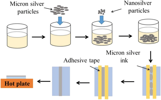
The fabrication process for novel micron (NM) silver ink is shown in Fig. 1. For the preparation of the micron silver ink, 1–3 μm micron silver flakes were added into a mixture of water, ethanol, ethylene glycol and glycerol in a volume ratio of about 21.0![[thin space (1/6-em)]](https://www.rsc.org/images/entities/char_2009.gif) :
:![[thin space (1/6-em)]](https://www.rsc.org/images/entities/char_2009.gif) 9.0
9.0![[thin space (1/6-em)]](https://www.rsc.org/images/entities/char_2009.gif) :
:![[thin space (1/6-em)]](https://www.rsc.org/images/entities/char_2009.gif) 39.5
39.5![[thin space (1/6-em)]](https://www.rsc.org/images/entities/char_2009.gif) :
:![[thin space (1/6-em)]](https://www.rsc.org/images/entities/char_2009.gif) 30.5. The solid loading of micron silver flakes for the conductive ink was 60 wt%. These were mechanically stirred for one hour at room temperature. Next, a small amount of 20–50 nm nanosilver particles was added into the ink and mixed. After two hours of mechanical stirring, the micron silver flakes and nanoparticles could be well coated by organic shells. The micron silver inks were deposited onto polyethylene terephthalate (PET) substrate using a screen-printing method. Finally, the sintered silver pattern was formed after heating, holding and cooling stages.
30.5. The solid loading of micron silver flakes for the conductive ink was 60 wt%. These were mechanically stirred for one hour at room temperature. Next, a small amount of 20–50 nm nanosilver particles was added into the ink and mixed. After two hours of mechanical stirring, the micron silver flakes and nanoparticles could be well coated by organic shells. The micron silver inks were deposited onto polyethylene terephthalate (PET) substrate using a screen-printing method. Finally, the sintered silver pattern was formed after heating, holding and cooling stages.
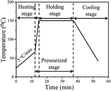
Fig. 2 shows the temperature profile of the NM silver ink. In the heating stage, the sample was first heated from room temperature to 70 °C, for the removal of organics, before sintering.28 Then, pressure was applied onto the pattern with a rapid heating rate to obtain a higher sintering driving force at low temperatures. In the holding stage, the grain growth will be accelerated by prolonging the holding time, with the help of diffusion bonding between silver particles.29 The pressure is also beneficial for diffusion bonding between micron silver flakes and nanosilver particles, to form a more uniform and dense sintered structure. In the cooling stage, slow cooling, i.e., cooling within the furnace, was used to reduce cracks caused by thermal stress.30
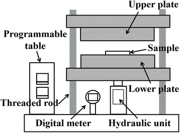
The surface morphologies of the sintered silver patterns before and after sintering were observed by scanning electron microscopy (SEM, S-4800, Hitachi, Japan). The resistivity of the sintered silver patterns was measured using a four-point probe (RTS-8, Probes Tech, China).31 The pore distribution of the sintered silver patterns was obtained using an image processing method.32 The pores and sintered silver pattern could be distinguished by the pixel threshold because the color of the pores was darker than that of sintered silver. The total area of the sintered silver pattern (S) and the pore area (S0) were measured using Matlab software. The porosity (ζ) was calculated from the equation, ζ = S0/S. Pressure was applied using a manual pressing machine (4128, Carver, USA), as shown in Fig. 3. The heating temperature was adjusted using a programmable table. After the sample was dried, it was put onto the lower plate and the upper plate was moved along the four threaded rods to keep the two plates horizontal. The pressure was controlled with a manual unit and displayed using a digital meter. During sintering, the upper and lower surfaces of the sample were covered with polyimide film to prevent the sample being polluted by the two plates.
3. Results and discussion
Fig. 4 shows the SEM image of the sintered silver pattern with micron silver inks under different applied pressures. For traditional micron (TM) silver inks, it is difficult to form dense bonding interactions at the sintering temperature of 140 °C (Fig. 4(a1)–(a3)), and there are few neck connections between the micron silver flakes. This can be ascribed to the low surface energy of the micron silver particles, which lowers the sintering driving force in the sintering process.33 In addition, there is no significant change in bonding interactions between micron silver flakes with pressures from 0 MPa to 10 MP. Fig. 4(b1)–(b3) shows the SEM surface morphology of the sintered silver pattern using the NM silver ink at 140 °C. The results show that the nanosilver particles are connected by diffusion to form larger particles, which are distributed into the gaps of the micron silver flakes. Moreover, the nanosilver particles are also in contact with adjacent micron silver flakes because of their larger surface energy. The growth of nanoparticles promotes close contact between the micron silver flakes.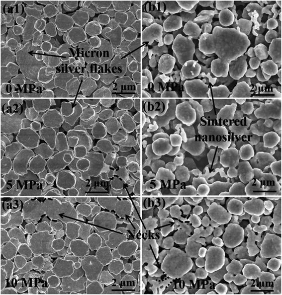 | ||
| Fig. 4 SEM micrographs of the sintered pattern with (a1)–(a3) traditional micron silver ink and (b1)–(b3) novel micron silver ink at a sintering temperature of 140 °C for 30 min. | ||
According to the Kirkendall effect, two solids diffuse into each other at different rates, and their boundary expands in the direction of the faster-moving species.34,35 Nanosilver particles are particularly susceptible to diffusion bonding, compared with micron silver flakes, because they have an extremely high surface area and volume ratio.18 As such, the boundary between nanosilver particles and micron silver flakes will slowly move towards the nanosilver particles, which may promote diffusion bonding between the nanosilver and micron silver flakes. The sintered silver pattern using the NM ink has a denser structure under a pressure of 10 MPa, as shown in Fig. 4(b3). The stronger bonding interactions in the sintered pattern could be obtained with the help of pressure. This was also confirmed by the Mackenzie–Shuttleworth sintering model, which illustrates the close relationship between densification rate and pressure.36 The highest densification rate should occur at a pressure of 10 MPa, resulting in a denser structure.
Fig. 5 shows the SEM images of sintered silver patterns at different sintering temperatures. There are no obvious neck connections between the two kinds of inks at low temperatures, i.e., 100 °C. When the sintering temperature reached 140 °C, obvious neck connections appeared in the sintered pattern with the NM ink, especially bonding interactions between nanosilver particles and micron silver flakes. The reason for this densification on sintering is that the diffusion between the silver particles is dominated by grain boundary diffusion at high temperatures.37 Vacancies can be injected into adjacent grains between grain boundaries by an atomic mechanism, resulting in the Kirkendall effect, and thus significantly enhancing the diffusion of nearby crystal regions.38
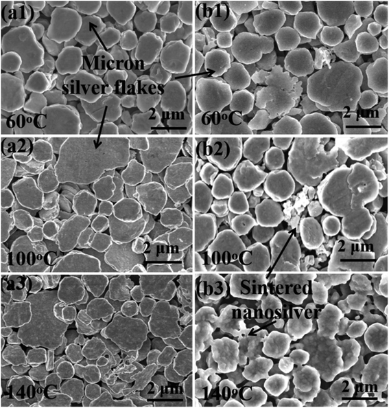 | ||
| Fig. 5 SEM micrographs of the sintered pattern with (a1)–(a3) traditional micron silver ink and (b1)–(b3) novel micron silver ink at sintering temperatures of 60 °C, 100 °C and 140 °C. | ||
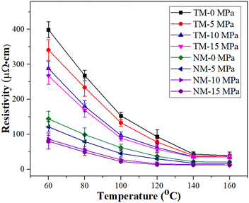
The electrical resistivity decreases with increase in sintering temperature, as given in Fig. 6. Although the TM silver inks have a relatively high electrical resistivity, i.e., 5.17 × 10⁻⁵ Ω cm at 140 °C, the decrease in electrical resistivity, i.e., 3.52 × 10⁻⁵ Ω cm, is not obvious, even at a pressure of 15 MPa (TM-15). The reason for this may be that diffusion bonding between micron silver flakes is difficult because of their low surface energy. For the NM silver inks, the electrical resistivity of the sintered silver pattern is 18.3 × 10⁻⁶ Ω cm, which is 64.6% lower than that of the TM silver ink at a sintering temperature of 140 °C. Meanwhile, bonding interactions between nanosilver particles and micron silver flakes can be easily achieved, and can be attributed to the larger surface energy of the nanosilver particles, which will promote diffusion bonding with micron silver flakes. When the pressure applied was 10 MPa (NM-10), the electrical resistivity of the sintered silver pattern could reach 11.5 × 10⁻⁶ Ω cm due to an increase in the sintering driving force. At a sintering temperature of 140 °C, the electrical resistivity of the sintered silver pattern with NM-15 MPa is 11.2 × 10⁻⁶ Ω cm, which is only 2.6% lower than that of the sintered silver pattern with NM-10 MPa. Considering the cost of pressurization, a pressure of 10 MPa is sufficient for sintering of NM silver ink.
As seen in Fig. 7, prolonging the holding time can further promote bonding interactions between silver particles, thereby reducing the electrical resistivity of the sintered silver patterns. For the TM silver ink, the electrical resistivity of the sintered silver patterns decreases slowly with increase in holding time. The electrical resistivity of the sintered silver pattern with a holding time of 30 min (4.9 × 10⁻⁵ Ω cm) was only 5.7% lower than with a holding time of 1 min (5.2 × 10⁻⁵ Ω cm). Such results illustrate that it is difficult to achieve dense conductive patterns by low-temperature sintering of 1–3 μm micron silver flakes. For the NM silver ink, i.e., NM-15, the electrical resistivity of the sintered silver pattern with a holding time of 30 min (10.5 × 10⁻⁶ Ω cm) was 6.3% lower than that at 1 min (11.2 × 10⁻⁶ Ω cm). The pressure can further improve the sintering driving force between nanosilver particles and micron silver flakes, thus promoting their bonding interactions. These experiments indicate that adding a small amount of nanosilver particles is an effective way to improve the conductivity of sintered silver patterns using micron silver inks.
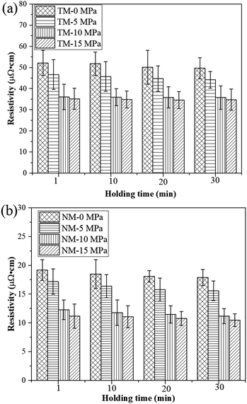 | ||
| Fig. 7 Electrical resistivity of the sintered silver pattern with (a) traditional micron silver ink and (b) novel micron silver ink at different holding times. | ||
To demonstrate the applicability of printed conductive patterns, the sintered silver patterns were used as conductive wires to power light-emitting diodes (LEDs) during bending, twisting and rolling tests, as shown in Fig. 8. For the NM silver ink, the LED worked normally when the sintered silver pattern was used as the conductive wire. The LED still maintained stable brightness and did not go out when the sintered silver pattern was bent, twisted and rolled. The results show that the sintered silver pattern using NM silver ink has high conductivity and reliability for practical applications. For the TM silver ink, the LED can be lit when straight and bent sintered silver patterns are used, but the brightness is very weak due to the high electrical resistivity of the sintered silver pattern with TM silver ink. Nevertheless, the LED goes out when the sintered silver pattern underwent twisting and rolling tests, mainly caused by the non-dense diffusion of the sintered pattern derived from the low surface energy of the micron silver flakes. During repeated bending processes, the LED also went out due to short circuiting of the sintered silver pattern, which is attributable to the breaking of weak interactions between the micron silver flakes. For the sintered silver pattern with NM silver ink, the bonding interactions between the micron silver flakes are closely connected, with the help of the small amount of added nanosilver particles. Moreover, the necks between the micron silver flakes are denser and less prone to fracture during bending, twisting and rolling tests.
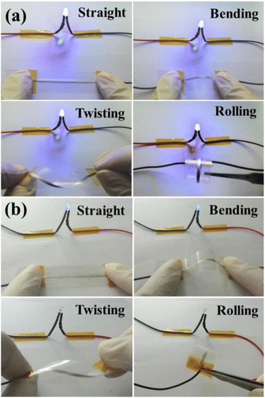 | ||
| Fig. 8 Photographs of the LED circuit with the sintered silver pattern during bending, twisting and rolling tests with (a) novel micron silver ink and (b) traditional micron silver ink. | ||
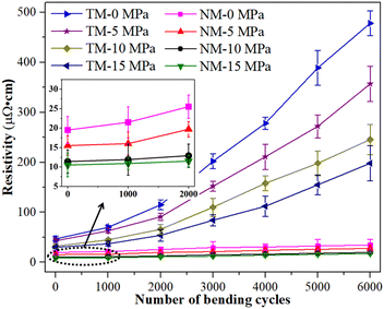
In order to further study the reliability of the sintered silver patterns using NM silver ink, electrical resistivity changes before and after bending cycles were also measured (given in Fig. 9). All the samples were sintered at the sintering temperature of 140 °C for 30 min. The test condition was that the bending angle remained at about 90° during the bending cycles. The results show that the electrical resistivity of the sintered silver pattern with NM-15 had no significant change after 6000 bending cycles, and the electrical resistivity increased from 10.5 × 10⁻⁶ Ω cm to 17.6 × 10⁻⁶ Ω cm. The NM-10 sample exhibited a similar reliability for the sintered silver pattern to that for NM-15. This indicates that a small amount of nanosilver particles can help micron silver particles to achieve reliable bonding interactions. The necks between the micron silver flakes are closely connected, and so they can withstand long periods of bending cycles.
For the sintered pattern of NM-0, the electrical resistivity increased to 33.2 × 10⁻⁶ Ω cm after 6000 bending cycles. This indicates that the bonding interactions between the nanosilver particles and the micron silver flakes have not yet achieved a dense structure, without an applied pressure. Thus, the necks between the micron silver flakes are liable to break after a long period of bending cycles. Therefore, the electrical resistivity of the sintered silver pattern increases rapidly after fracture of the necks. For the sintering patterns for TM-0 and TM-15, their initial resistivity was relatively high (4.7 × 10⁻⁵ Ω cm and 3.1 × 10⁻⁵ Ω cm, respectively), and the electrical resistivity also increased rapidly (4.8 × 10⁻⁴ Ω cm and 1.9 × 10⁻⁴ Ω cm, respectively) after 6000 bending cycles. This is mainly due to the poor bonding quality of the sintered silver patterns using TM silver ink, which is easily cracked after a long period of bending cycles. Moreover, the sintered silver patterns are porous structures, and the interactions between the micron silver flakes are extremely fragile. The reason for the rapid increase in electrical resistivity may be the contact loss between the micron silver flakes when the necks begin to break.
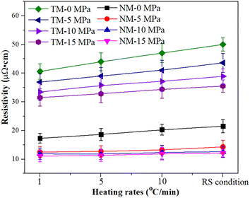
Fig. 10 shows the electrical resistivity of micron silver ink at different heating rates. First, the micron silver ink was heated from room temperature to 70 °C at a heating rate of 5 °C min−1. Then, it was heated to 140 °C with a holding time of 30 min at different heating rates. The RS condition means that the ink was heated without use of a heating process from 70 °C to 140 °C. The electrical resistivity of the sintered silver pattern with a pressure of 5 MPa, i.e., 14.3 × 10⁻⁶ Ω cm, was lower than that for pressureless sintering because the pressure provides a higher driving force for sintering. Heating rate has almost no impact on the electrical resistivity of the sintered silver pattern for the NM silver ink. Under a pressure of 15 MPa, the sintered silver pattern under RS conditions (11.6 × 10⁻⁶ Ω cm) has a similar electrical resistivity to that at 1 °C min−1 (11.9 × 10⁻⁶ Ω cm). Under RS conditions, the electrical resistivity of the sintered pattern with 10 MPa was 12.1 × 10⁻⁶ Ω cm, which is also close to that of the sintered pattern with 15 MPa. On the other hand, the electrical resistivity of the sintered pattern with TM-15 MPa was 3.6 × 10⁻⁵ Ω cm, which is 3.1 times higher than that of the sintered pattern with NM-15 MPa.
Fig. 11 exhibits the pore distribution of the sintered silver pattern using commercial nanosilver ink and the NM silver ink. Results show that the sintered patterns using NM silver ink have large pores, i.e., more than 1 μm, which are 50 times larger than those using nanosilver ink. Large pores can provide a better channel for the evaporation of organics. For the nanosilver ink, the pores between the nanosilver particles are relatively small, which is not conducive to rapid evaporation of organics around the silver particles. When the organics are completely evaporated, the silver particles begin to connect with each other. Therefore, the nanosilver ink needs a slower heating rate to help in the evaporation of organics, while the NM silver ink can be heated quickly with the help of the large pores between the micron silver flakes.
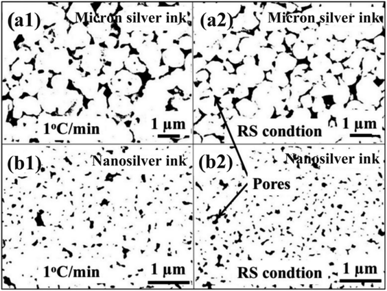 | ||
| Fig. 11 Pore distribution of the sintered silver pattern between (a1) and (a2) micron silver ink and (b1) and (b2) nanosilver ink. | ||
For the nanosilver ink, the sintered silver also tends to become denser with decreasing heating rate, and a higher portion of smaller pores in the sintered silver pattern, i.e., 72.9%, was obtained at a heating rate of 1 °C min−1 (Fig. 12(a)). In addition, a large frequency of 84.6% can be observed in the sintered silver pattern with extended holding time (Fig. 12(b)). When the silver pattern was heated directly to the sintering temperature, however, many as-dried nanoparticles still existed inside. Partial sintering may prevent the formation of necks between silver particles. For the NM silver ink, a high portion of larger pores was found in the sintered silver pattern. The difference in the frequency of the larger pores between 1 °C min−1 (66.5%) and the RS condition (69.9%) is not evident. For the smaller pores, a higher portion of pores are found in the sintered silver pattern at a holding time of 30 min (Fig. 12(d)). The results show that prolonging the holding time can increase the fraction of smaller pores in the NM silver ink due to neck growth.
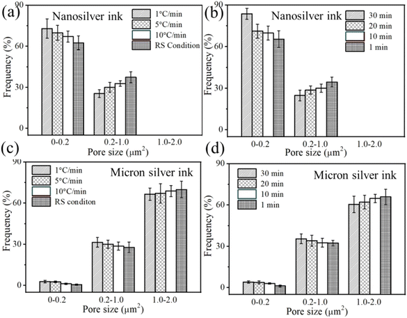 | ||
| Fig. 12 Pore-size distribution at different heating rates and holding times between (a and b) nanosilver ink and (c and d) micron silver ink. | ||
The advantage of the RS condition is elimination of the heating time from room temperature to the sintering temperature, which can greatly reduce the total sintering time. Additionally, there are two further advantages for the practical application of NM silver inks. First, micron silver flakes are cheaper than nanosilver particles, which can reduce the cost of silver ink and promote its wide application in conductive patterns. Second, micron silver ink has a high conductivity due to its high silver content, i.e., more than 40%, and can withstand a small voltage drop of large current capacity.39
The reliability of the sintered silver pattern using micron silver ink at different heating rates was also studied. As seen in Fig. 13, the different heating rates have a significant influence on the electrical resistivity of the sintered silver pattern after 6000 bending cycles. The electrical resistivity of the sintered silver pattern with 1 °C min−1 and RS condition increases by 15.6 × 10⁻⁶ Ω cm and 44.2 × 10⁻⁶ Ω cm, respectively. The reason for this may be that the RS condition has passed the heating stage, leading to reduction of the sintering time. Unfortunately, less sintering time results in non-dense sintering between silver particles. The holding time of the sintered silver pattern under the RS condition was also extended by 20 minutes (RS-20). The results show that the electrical resistivity increases by only 16.4 × 10⁻⁶ Ω cm after 6000 bending cycles. The reliability of the sintered silver pattern with the RS-20 condition can be improved to a level similar to that at heating of 1 °C min−1. The total sintering time of the sintered silver pattern with the RS-20 condition was only 29 min, which is 63.3% lower than for a rate of 1 °C min−1.
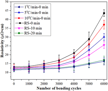 | ||
| Fig. 13 Electrical resistivity of the silver patterns as a function of bending cycles with different heating rates. | ||
4. Conclusion
In this study, the fabrication of dense bonding interactions was achieved for micron silver ink with the help of the addition of a small amount of nanosilver particles. The size of the micron silver flakes ranged from 1 μm to 3 μm. The growth of nanosilver particles is beneficial for dense contact between the micron silver flakes, enabling the formation of necks and achieving highly conductive silver patterns. Importantly, rapid sintering can be achieved by removing the heating process from 70 °C to the sintering temperature. Under a pressure of 10 MPa, the electrical resistivity of the sintered silver patterns was 10.8 × 10⁻⁶ Ω cm at 140 °C for 30 min. After bending, twisting and rolling tests, an LED remained illuminated and worked normally. In addition, the electrical resistivity of the sintered silver pattern under the RS-20 condition increased by only 16.4 × 10⁻⁶ after 6000 bending cycles. It should be noted that this method of making micron silver inks has potential applications in highly reliable and conductive patterns.Conflicts of interest
There are no conflicts to declare.Acknowledgements
This work was supported by the Tianjin Education Commission Scientific Research Project (No. 2018KJ187) and the Special Fund for Basic Scientific Research Business of Central Public Research Institutes (K-JBYWF-2022-T01).References
- W. Z. Heng, S. Solomon and W. Gao, Adv. Mater., 2022, 34, 2107902 CrossRef CAS PubMed.
- D. Beri, S. Budiman, N. Y. Sudiar, A. Yusra, E. Erianjoni, G. Ganefri and A. Amran, RSC Adv., 2022, 12, 24640–24646 RSC.
- Y. Mou, H. Cheng, H. Wang, Q. L. Sun, J. X. Liu, Y. Peng and M. X. Chen, Appl. Surf. Sci., 2019, 475, 75–82 CrossRef CAS.
- J. L. Xiang, G. Y. Zhou, Y. Hong, W. He, S. X. Wang, Y. M. Chen, C. Wang, Y. Tang, Y. K. Sun and Y. K. Zhu, Appl. Surf. Sci., 2022, 587, 152848 CrossRef CAS.
- Y. H. Liu, Y. D. Shen, X. R. Li, Y. Y. Dang, L. T. Li and K. Yang, RSC Adv., 2022, 12, 13267–13278 RSC.
- K. Black, J. Singh, D. Mehta, S. Sung, C. J. Sutcliffe and P. R. Chalker, Sci. Rep., 2016, 6, 20814 CrossRef CAS PubMed.
- H. Shahariar, I. Kim, H. Soewardiman and J. S. Jur, ACS Appl. Mater. Interfaces, 2019, 11(6), 6208–6216 CrossRef CAS PubMed.
- P. C. Wu, L. Y. Zhou, S. Lv, J. Z. Fu and Y. He, J. Mater. Chem. C, 2021, 9, 3070–3080 RSC.
- X. Z. Zhu, A. Q. Guo, J. Xu and C. X. Kan, CrystEngComm, 2020, 22, 8421–8429 RSC.
- H. Menon, R. Aiswarya and K. P. Surendran, RSC Adv., 2017, 7, 44076–44081 RSC.
- A. S. Pillai, A. Chandran and S. K. Peethambharan, Applied Materials Today, 2021, 23, 100987 CrossRef.
- P. Z. Wang, K. Liu, X. X. Wang, Z. T. Meng, Z. F. Xin, C. C. Cui, F. Y. Quan, K. W. Zhang and Y. Z. Xia, J. Mater. Chem. A, 2022, 10, 15776–15784 RSC.
- H. M. Ren, Y. Guo, S. Y. Huang, K. Zhang, M. M. F. Yuen, X. F. Fu, S. H. Yu, R. Sun and C. P. Wong, ACS Appl. Mater. Interfaces, 2015, 7, 13685–13692 CrossRef CAS PubMed.
- L. Zhou, X. L. Chen, W. M. Su, Z. Cui and W. Y. Lai, Adv. Mater. Interfaces, 2022, 9, 2102548 CrossRef CAS.
- F. Widdascheck, D. Bischof and G. Witte, Adv. Funct. Mater., 2021, 31, 2106687 CrossRef CAS.
- I. Kim, H. Shahariar, W. F. Ingram, Y. Zhou and J. S. Jur, Adv. Funct. Mater., 2019, 29, 1807573 CrossRef.
- K. Ryu, Y. J. Moon, K. Park, J. Y. Hwang and S. J. Moon, J. Electron. Mater., 2016, 45, 312–321 CrossRef CAS.
- P. Bowen and C. Carry, Powder Technol., 2002, 128, 248–255 CrossRef CAS.
- J. C. Kim, K. H. Auh and D. M. Martin, Modell. Simul. Mater. Sci. Eng., 2000, 8, 159 CrossRef CAS.
- W. F. Shao, Z. Gang, P. L. Zhu, Y. Zhang, Q. L. Ouyang, R. Sun, C. H. Chen and C. P. Wong, J. Mater. Sci.: Mater. Electron., 2018, 29, 4432–4440 CrossRef CAS.
- I. J. Fernandes, A. F. Aroche, A. Schuck, P. Lamberty, C. R. peter, W. Hasenkamp and T. L. A. C. Rocha, Sci. Rep., 2020, 10, 8878 CrossRef CAS PubMed.
- A. Remadevi, S. A. Jose1, D. K. Sreedeviamma and K. P. Surendran, J. Mater. Sci., 2021, 56, 15971–15984 CrossRef CAS.
- L. X. Mo, Z. X. Guo, Z. G. Wang, L. Yang, Y. Fang, Z. Q. Xin, X. Li, Y. J. Chen, M. J. Cao, Q. Q. Zhang and L. H. Li, Nanoscale Res. Lett., 2019, 14, 197 CrossRef PubMed.
- H. Wadayama, T. Okabe and J. Taniguchi, Microelectron. Eng., 2018, 193, 47–53 CrossRef CAS.
- D. D. Li, W. Y. Lai, F. Feng and W. Huang, Adv. Mater. Interfaces, 2021, 8, 2100548 CrossRef CAS.
- T. H. Du, C. L. Tang, B. Xing, Y. B. Lu, F. L. Huang and C. C Zuo, J. Electron. Mater., 2019, 48, 231–237 CrossRef CAS.
- L. Y. Xu, G. Y. Yang, H. Y. Jing, J. Wei and Y. D. Han, Nanotechnology, 2013, 24, 355204 CrossRef CAS PubMed.
- G. N. Yang, P. Y. Wang, Y. Liu, S. Z. Lu, B. Luo, T. Lai, S. W. Ta, T. Y. Lin, J. Y. Luo, Y. Zhang and C. Q. Cui, J. Alloys Compd., 2022, 923, 166271 CrossRef CAS.
- S. S. Yao, J. J. Xing, J. F. Zhang, S. H. Xiong, Y. X. Yang, X. Yuan, H. B. Li and H. Tong, IEEE Trans. Compon., Packag., Manuf. Technol., 2018, 29, 18540–18546 CAS.
- S. J. Mortaza, W. Z. Kuang, C. C. Dun and Y. L. Zhang, Adv. Funct. Mater., 2019, 29, 1901930 CrossRef.
- Y. Mou, H. Cheng, H. Wang, Q. L. Sun, J. X. Liu, Y. Peng and M. X. Chen, Appl. Surf. Sci., 2019, 475, 75–82 CrossRef CAS.
- N. Chawla and X. Deng, Mater. Sci. Eng., A, 2005, 390, 98–112 CrossRef.
- X. K. Tian, S. C. Lin, J. Yan and C. Y. Zhao, Chem. Eng. J., 2022, 428, 131229 CrossRef CAS.
- E. Kirkendall, L. Thomassen and C. Uethegrove, Trans. AIME, 1939, 133, 186 Search PubMed.
- L. Klinger and E. Rabkin, Acta Mater., 2011, 59, 1389–1399 CrossRef CAS.
- J. K. Mackenzie and R. Shuttleworth, Proc. Phys. Soc., 1949, 62, 833–852 CrossRef.
- M. Tavakoli, M. H. Malakooti, H. Paisana, Y. Ohm, D. G. Marques, P. A. Lopes, A. P. Piedade, A. T. D. Almeida and C. Majidi, Adv. Mater., 2018, 30, 1801852 CrossRef PubMed.
- H. C. Yu, A. V. D. Ven and K. Thornton, Appl. Phys. Lett., 2008, 93, 091908 CrossRef.
- T. Igari, Y. Ono, K. Shigeta, T. Ueta, N. C. Kasuga and K. Yamaguchi, Mater. Chem. Phys., 2022, 277, 125467 CrossRef CAS.
| This journal is © The Royal Society of Chemistry 2023 |

