 Open Access Article
Creative Commons Attribution 3.0 Unported Licence
Effect of fibers on chloride transport in mortars under unsaturated and saturated conditions
Danying Gaoab,
Zhudi Caoab,
Lin Yang *a,
Honglei Chang*c,
Junru Lia,
Guowen Sund and
Hongwei Liue
aYellow River Laboratory, Zhengzhou University, Zhengzhou 450001, China. E-mail: yanglin06142@zzu.edu.cn
bSchool of Water Conservancy and Civil Engineering, Zhengzhou University, Zhengzhou 450001, China
cSchool of Qilu Transportation, Shandong University, Jinan 250002, China. E-mail: hlchang@sdu.edu.cn
dSchool of Materials Science and Engineering, Shijiazhuang Tiedao University, Shijiazhuang 050043, China
eWater Conservancy Bureau of Changyuan, Changyuan 453400, China
First published on 24th February 2023
Abstract
The effect of steel fibers (0–1.5% by volume) and polypropylene fibers (0–0.5% by volume) on chloride transport in mortars under unsaturated and saturated conditions was investigated using a natural immersion method. Moreover, the micromorphology of the fiber–mortar interface and the pore structure of fiber reinforced mortars were detected using scanning electron microscopy (SEM) and mercury intrusion porosimetry (MIP), respectively. The results show that both of the steel fibers and polypropylene fibers have an insignificant effect on the chloride diffusion coefficient of mortars, no matter under unsaturated or saturated conditions. The incorporation of steel fibers has no obvious action on the pore structure of mortars, and the interfacial zone around the steel fibers is not a preferential path for chloride transport. However, the addition of 0.1–0.5% polypropylene fibers refines the pore size of mortars, and yet slightly increases the total porosity. The polypropylene fiber–mortar interface is insignificant, while the agglomerate of polypropylene fibers exists.
1. Introduction
Concrete is widely used in infrastructure construction owing to its excellent mechanical strength, durability, low cost, among other desirable properties.1,2 However, ordinary concrete has high brittleness and low fatigue resistance, and cracks easily under the action of internal and external factors, such as load, temperature and humidity changes, shrinkage, and so on. In severe environments, hazardous substances (e.g. Cl−) in the external environment readily enter the concrete through cracks, promoting internal steel corrosion, concrete expansion and spalling.3–5 In this context, adding fibers to ordinary concrete can effectively increase its toughness, tensile strength and flexural strength. Specifically, the randomly distributed fibers in concrete limit the expansion and cracking of concrete and improve its crack resistance.6In recent years, various fibers, such as steel fibers, polypropylene fibers, and polyvinyl alcohol fibers, have been added to concrete to improve its performance.7,8 Among these, polypropylene fibers and steel fibers are the most widely used in concrete structures, because polypropylene fibers exhibit high crack resistance and steel fibers greatly improve the tensile strength of concrete. The addition of fibers inevitably affects the transmission of external hazardous substances while improving crack resistance of concrete and the mechanical properties. Some studies indicated that the addition of steel fiber improved the resistance to chloride permeability of concrete.9 In contrast, Hwang10 showed the chloride diffusion coefficient increased by 2–3 times upon adding steel fibers to ordinary concrete. The other researchers also obtained the similar conclusions.11 Nevertheless, Berrocal et al.12 indicated that the steel fibers did not greatly alter the chloride diffusion coefficient of uncracked concrete. Similarly, Frazao et al.13 indicated that the addition of steel fibers did not enhance the impermeability of concrete, but improve the flexural properties and energy absorption ability of cracked concrete. Ramezanianpour et al.14 investigated the impermeability of polypropylene fiber reinforced concrete by the electric flux method, and concluded that the polypropylene fibers improved the resistance to chloride permeability. However, Toutanji et al.6 found that the addition of polypropylene fibers reduced the resistance to chloride permeability, caused by the poor dispersion of fibers and poor adhesion to the matrix. Thus, the conclusions of previous studies on this topic are contradictory. Moreover, Behfarnia et al.15 compared the chloride resistance of polypropylene fibers and steel fibers, and reported that the effect of polypropylene fibers was better than the steel fibers at all dosages.
The inconsistent conclusions mentioned previously are mainly due to the use of diverse test methods. According to the measurement time, chloride migration can be analyzed by slow and rapid methods.16 Specifically, electrometric method that accelerates the migration rate of chloride ions in concrete by applying an external electric field, such as electric flux, rapid chloride migration (RCM), NEL Permit, AC impedance spectroscopy technology, etc.17,18 However, these methods are not suitable to test the chloride transport of steel fiber reinforced concrete, since the steel fibers are conductive and increase the electrical conductivity of concrete.19 Consequently, the experimental results cannot accurately reflect the migration characteristics of chloride ions in concrete. Thus, the use of rapid methods has been discredited by many scholars.20–22 Compared to the electrical acceleration method, the natural diffusion by immersing in salt solution is a reliable method to access the chloride diffusion of steel fiber reinforced concrete.23–25 Moreover, more than 90% of the concrete structures are in unsaturated state during the actual service, even though they are immersed in water for many years and difficult to be saturated.26,27 Thus, the saturation degree of concrete is an important factor influencing chloride transport, which should also be considered.28
This study focused on the effect of polypropylene fibers and steel fibers on chloride transport in mortars under unsaturated and saturated conditions. In addition, the effect of fibers on the fiber–mortar interface and pore structure of mortars were also investigated.
2. Experiment and method
2.1 Raw materials
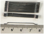
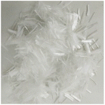
In this work, PO 42.5 ordinary Portland cement (in Chinese standard) was used. The chemical composition of cement, as shown in Table 1, was measured by X-ray fluorescence method. The fineness modulus of natural river sand was 2.71. Hooked-ended steel fibers (SF) and polypropylene fibers (PPF) were used, and their physical parameters are shown in Table 2. NaCl powder (analytical reagent) and deionized water were used for the preparation of NaCl solution.2.2 Mix proportion and specimen preparation
The water-to-cement ratio (W/C) was maintained at 0.5, and a constant mass ratio of cement to sand of 1![[thin space (1/6-em)]](https://www.rsc.org/images/entities/char_2009.gif) :
:![[thin space (1/6-em)]](https://www.rsc.org/images/entities/char_2009.gif) 3 was used. For SF mortars, the amounts of steel fibers were 0, 0.5%, 1.0% and 1.5% (by volume fraction), respectively. Meanwhile, for the mortars blended with PPF, the volume fractions of polypropylene fibers were 0, 0.1%, 0.3% and 0.5%, respectively. For the investigation of chloride transport in mortars, specimens with a height of 200 mm and diameter of 100 mm were prepared and cured in water for 60 days.29 In addition, cubic specimens (100 mm in the side length) were molded and cured at 20 °C/95% RH for 28 days, and Table 3 shows their compressive strengths. It can be seen that the compressive strength of mortar increases gradually with the SF content increasing from 0% to 1.5%, while the addition of 0–0.5% PPF has no significant effect on the compressive strength of mortar.
3 was used. For SF mortars, the amounts of steel fibers were 0, 0.5%, 1.0% and 1.5% (by volume fraction), respectively. Meanwhile, for the mortars blended with PPF, the volume fractions of polypropylene fibers were 0, 0.1%, 0.3% and 0.5%, respectively. For the investigation of chloride transport in mortars, specimens with a height of 200 mm and diameter of 100 mm were prepared and cured in water for 60 days.29 In addition, cubic specimens (100 mm in the side length) were molded and cured at 20 °C/95% RH for 28 days, and Table 3 shows their compressive strengths. It can be seen that the compressive strength of mortar increases gradually with the SF content increasing from 0% to 1.5%, while the addition of 0–0.5% PPF has no significant effect on the compressive strength of mortar.
| Type of fiber | W/C | Cement to sand ratio | Fiber content (%) | Compressive strength (MPa) |
|---|---|---|---|---|
| SF | 0.5 | 1![[thin space (1/6-em)]](https://www.rsc.org/images/entities/char_2009.gif) : :![[thin space (1/6-em)]](https://www.rsc.org/images/entities/char_2009.gif) 3 3 |
0 | 41.9 |
| 0.5 | 42.6 | |||
| 1.0 | 46.4 | |||
| 1.5 | 48.2 | |||
| PPF | 0.5 | 1![[thin space (1/6-em)]](https://www.rsc.org/images/entities/char_2009.gif) : :![[thin space (1/6-em)]](https://www.rsc.org/images/entities/char_2009.gif) 3 3 |
0 | 41.9 |
| 0.1 | 42.1 | |||
| 0.3 | 43.6 | |||
| 0.5 | 39.2 |
2.3 Experiment methods
 | (1) |
According to the chloride content distribution, Fick's second law with error function solution was used to calculate the chloride diffusion coefficient,30 as follows:
 | (2) |
3. Results and analysis
3.1 Effect of steel fiber content on chloride transport
 | ||
| Fig. 2 Chloride content distribution of unsaturated mortars with different SF contents immersed in NaCl solution for different time. (a) 4 months, (b) 8 months and (c) 12 months. | ||
| Exposure time (months) | SF content (%) | CS (%) | D (×10−11 m2 s−1) | R2 |
|---|---|---|---|---|
| 4 | 0 | 0.44 | 8.29 | 0.973 |
| 0.5 | 0.39 | 7.27 | 0.955 | |
| 1.0 | 0.39 | 6.49 | 0.913 | |
| 1.5 | 0.35 | 6.36 | 0.960 | |
| 8 | 0 | 0.36 | 7.36 | 0.956 |
| 0.5 | 0.37 | 7.02 | 0.882 | |
| 1.0 | 0.35 | 6.04 | 0.958 | |
| 1.5 | 0.34 | 5.39 | 0.911 | |
| 12 | 0 | 0.44 | 6.53 | 0.967 |
| 0.5 | 0.43 | 5.88 | 0.943 | |
| 1.0 | 0.39 | 5.41 | 0.921 | |
| 1.5 | 0.35 | 4.84 | 0.951 |
 | ||
| Fig. 3 Chloride content distribution of saturated mortars with different SF contents immersed in NaCl solution for different time. (a) 4 months, (b) 8 months and (c) 12 months. | ||
| Exposure time (months) | SF content (%) | CS (%) | D (×10−12 m2 s−1) | R2 |
|---|---|---|---|---|
| 4 | 0 | 0.12 | 9.15 | 0.979 |
| 0.5 | 0.16 | 12.10 | 0.984 | |
| 1.0 | 0.19 | 13.0 | 0.961 | |
| 1.5 | 0.21 | 10.8 | 0.984 | |
| 8 | 0 | 0.19 | 7.64 | 0.995 |
| 0.5 | 0.26 | 9.89 | 0.995 | |
| 1.0 | 0.28 | 11.90 | 0.988 | |
| 1.5 | 0.29 | 8.88 | 0.990 | |
| 12 | 0 | 0.26 | 8.10 | 0.994 |
| 0.5 | 0.35 | 9.08 | 0.978 | |
| 1.0 | 0.33 | 10.80 | 0.984 | |
| 1.5 | 0.34 | 8.07 | 0.980 |
3.2 Effect of polypropylene fiber content on chloride transport
 | ||
| Fig. 4 Chloride content distribution of unsaturated mortars with different PPF contents immersed in NaCl solution for different time. (a) 4 months, (b) 8 months and (c) 12 months. | ||
| Exposure time (months) | PPF content (%) | CS (%) | D (×10−11 m2 s−1) | R2 |
|---|---|---|---|---|
| 4 | 0 | 0.51 | 4.36 | 0.944 |
| 0.1 | 0.56 | 3.12 | 0.99 | |
| 0.3 | 0.65 | 3.33 | 0.958 | |
| 0.5 | 0.69 | 3.29 | 0.982 | |
| 8 | 0 | 0.49 | 2.50 | 0.845 |
| 0.1 | 0.51 | 2.09 | 0.934 | |
| 0.3 | 0.67 | 2.12 | 0.891 | |
| 0.5 | 0.71 | 2.13 | 0.88 | |
| 12 | 0 | 0.59 | 2.31 | 0.891 |
| 0.1 | 0.59 | 2.03 | 0.944 | |
| 0.3 | 0.66 | 2.05 | 0.886 | |
| 0.5 | 0.70 | 2.05 | 0.89 |
 | ||
| Fig. 5 Chloride content distribution of saturated mortars with different PPF contents immersed in NaCl solution for different time. (a) 4 months, (b) 8 months and (c) 12 months. | ||
| Exposure time (months) | PPF content (%) | CS (%) | D (×10−12 m2 s−1) | R2 |
|---|---|---|---|---|
| 4 | 0 | 0.35 | 16.40 | 0.992 |
| 0.1 | 0.34 | 12.00 | 0.992 | |
| 0.3 | 0.35 | 17.60 | 0.98 | |
| 0.5 | 0.4 | 18.90 | 0.976 | |
| 8 | 0 | 0.46 | 6.32 | 0.982 |
| 0.1 | 0.45 | 6.06 | 0.983 | |
| 0.3 | 0.54 | 7.84 | 0.989 | |
| 0.5 | 0.53 | 9.86 | 0.975 | |
| 12 | 0 | 0.55 | 4.47 | 0.942 |
| 0.1 | 0.5 | 4.12 | 0.978 | |
| 0.3 | 0.66 | 4.82 | 0.993 | |
| 0.5 | 0.74 | 4.96 | 0.99 |
3.3 Microstructure of fiber reinforced mortars
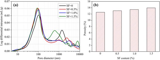 | ||
| Fig. 6 Pore structure of mortars with different contents of SF. (a) Pore size distribution, (b) total porosity. | ||
As we know, the cement-based material is a typical porous material, since the pore size spans over three scales (micro, meso and macro) and several orders of magnitude (10−9–10−3 m), including gel pores, capillary pores and voids.34 Chloride transport in the cement-based material is governed by the pore structure (pore size, porosity, and connectivity) and interfacial transition zone, and usually the micro-pores provide continuous paths for chloride migration, no matter under saturated and unsaturated conditions.35,36 The addition of 0–1.5% SF has no significant effect on the pore structure of mortars, therefore, it does not obviously change the chloride diffusion coefficients.
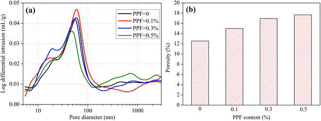
Fig. 7 shows the pore structure of PPF mortars. The PPF content has a significant effect on the pore structure of mortar. With the PPF content increasing from 0% to 0.5%, the pore size distribution has a small movement to the left (the smaller pore diameter), but not significantly. Especially, when the PPF content comes up to 0.5%, the proportion of small pores (<100 nm) has an obvious decrease while the proportion of large pores (200–1000 nm) increases slightly. As shown in Fig. 7b, the total porosity of mortar increases from 12.55% to 17.67% when the PPF content increases from 0% to 0.5%. Overall, adding PPF increases the total porosity of mortar but has a decrease in pore size. This is the reason that the addition of PPF has no significant effect on chloride transport in mortars under unsaturated and saturated conditions.
4. Conclusions
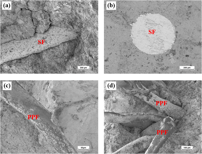
The effect of polypropylene fiber and steel fiber content on chloride transport in unsaturated and saturated mortars was investigated in detail. Moreover, the pore structure of fiber reinforced mortars and the micromorphology of fiber–mortar interface were detected.(1) When the SF content increases from 0 to 1.5%, the chloride diffusion coefficient of mortar has insignificant variation under both of the unsaturated and saturated conditions. This is because the addition of 0–1.5% SF has unremarkable effect on the pore structure of mortars, including pore size distribution and total porosity. Besides, the interfacial effect caused by the incorporation of SF is insignificant.
(2) Compared with the mortars without fibers, the addition of 0.1–0.5% PPF has no obvious effect on the chloride diffusion coefficient, no matter under unsaturated and saturated conditions. However, when the PPF content increases from 0% to 0.5%, the pore size of mortar has a slight decrease while the total porosity increases from 12.55% to 17.67%, mainly caused by the agglomerate of PPFs. With the addition of 0–0.5% PPF, the influence of pore size refinement and porosity improvement on chloride transport counteracts each other.
(3) Overall, with the addition of 0–1.5% SF or 0–0.5% PPF, chloride transport in the mortars has no insignificant variation. However, the chloride diffusion coefficient in unsaturated mortar is an order of magnitude higher than the saturated mortar. The saturation degree is a critical factor influencing the chloride transport.
Data availability
All data generated or used during the study appear in the submitted article.Conflicts of interest
The authors declare that they have no known competing financial interests or personal relationships that could have appeared to influence the work reported in this paper.Acknowledgements
This work was supported by the National Natural Science Foundation of China (No. 52078468 & 51808508), Natural Science Foundation of Henan Province (No. 222300420080) and the First-class Project Special Funding of Yellow River Laboratory (No. YRL22LT04). The authors extend their appreciation to the administrators.References
- K. Celik, C. Meral, M. Mancio, P. K. Mehta and P. Monteiro, A comparative study of self-consolidating concretes incorporating high-volume natural pozzolan or high-volume fly ash, Constr. Build. Mater., 2014, 67, 14–19 CrossRef.
- H. Chang, X. Wang, Y. Wang, S. Li, J. Wang, J. Liu and P. Feng, Influence of low vacuum condition on mechanical performance and microstructure of hardened cement paste at early age, Constr. Build. Mater., 2022, 346, 128358 CrossRef CAS.
- Q. F. Liu, Z. Hu, X. E. Wang, H. Zhao, K. Qian, L. J. Li and Z. Meng, Numerical study on cracking and its effect on chloride transport in concrete subjected to external load, Constr. Build. Mater., 2022, 325, 126797 CrossRef CAS.
- Z. Meng, Q. F. Liu, J. Xia, Y. Cai, X. Zhu, Y. Zhou and L. Pel, Mechanical-transport-chemical modelling of electrochemical repair methods for corrosion-induced cracking in marine concrete, Comput.-Aided Civ. Infrastruct. Eng., 2022, 37, 1854–1874 CrossRef.
- L. Yang, D. Gao, Y. Zhang and W. She, Study on water and chloride transport in cracked mortar using X-ray CT, gravimetric method and natural immersion method, Constr. Build. Mater., 2018, 76, 652–664 CrossRef.
- H. A. Toutanji, Properties of polypropylene fiber reinforced silica fume expansive-cement concrete, Constr. Build. Mater., 1999, 13, 171–177 CrossRef.
- S. T. Kang, Y. Lee, Y. D. Park and J. K. Kim, Tensile fracture properties of an Ultra High Performance Fiber Reinforced Concrete (UHPFRC) with steel fiber, Compos. Struct., 2010, 92, 61–71 CrossRef.
- X. Luo, W. Sun and S. Chan, Characteristics of high-performance steel fiber-reinforced concrete subject to high velocity impact, Cem. Concr. Res., 2000, 30(6), 907–914 CrossRef CAS.
- S. Abbas, A. M. Soliman and M. L. Nehdi, Exploring mechanical and durability properties of ultra-high performance concrete incorporating various steel fiber lengths and dosages, Constr. Build. Mater., 2015, 75, 429–441 CrossRef.
- J. P. Hwang, M. S. Jung, M. Kim and K. Y. Ann, Corrosion risk of steel fibre in concrete, Constr. Build. Mater., 2015, 101, 239–245 CrossRef.
- S. Teng, V. Afroughsabet and C. P. Ostertag, Flexural behavior and durability properties of high performance hybrid-fiber-reinforced concrete, Constr. Build. Mater., 2018, 182, 504–515 CrossRef CAS.
- C. G. Berrocal, K. Lundgren and I. Lofgren, Corrosion of steel bars embedded in fibre reinforced concrete under chloride attack: State of the art, Cem. Concr. Res., 2016, 80, 69–85 CrossRef CAS.
- C. Frazao, A. Camoes, J. Barros and D. Goncalves, Durability of steel fiber reinforced self-compacting concrete, Constr. Build. Mater., 2015, 80, 155–166 CrossRef.
- A. A. Ramezanianpour, M. Esmaeili, S. A. Ghahari and M. H. Najafi, Laboratory study on the effect of polypropylene fiber on durability, and physical and mechanical characteristic of concrete for application in sleepers, Constr. Build. Mater., 2013, 44, 411–418 CrossRef.
- K. Behfarnia and A. Behravan, Application of high performance polypropylene fibers in concrete lining of water tunnels, Mater. Des., 2014, 55, 274–279 CrossRef CAS.
- B. Park, S. Y. Jang, J. Y. Cho and J. Y. Kim, A novel short-term immersion test to determine the chloride ion diffusion coefficient of cementitious materials, Constr. Build. Mater., 2014, 57, 169–178 CrossRef.
- V. Elfmarkova, P. Spiesz and H. J. H. Brouwers, Determination of the chloride diffusion coefficient in blended cement mortars, Cem. Concr. Res., 2015, 78, 190–199 CrossRef CAS.
- P. Gao, J. Wei, T. Zhang, J. Hu and Q. Yu, Modification of chloride diffusion coefficient of concrete based on the electrical conductivity of pore solution, Constr. Build. Mater., 2017, 145, 361–366 CrossRef CAS.
- ASTM C1202, Standard Test Method for Electrical Indication of Concrete's Ability to Resist Chloride Ion Penetration, 2022 Search PubMed.
- Y. Wang and K. Fu, Comparisons of instantaneous chloride diffusion coefficients determined by RCM method and chloride natural diffusion test, Constr. Build. Mater., 2019, 223, 595–604 CrossRef CAS.
- P. A. M. Basheer, R. J. Andrews, D. J. Robinson and A. E. Long, 'PERMIT' ion migration test for measuring the chloride ion transport of concrete on site, NDT&E Int., 2005, 38(3), 219–229 CrossRef CAS.
- Y. Huang, J. Wei, R. Dong and H. Zeng, Chloride Ion Transmission Model under the Drying-wetting Cycles and Its Solution, J. Wuhan Univ. Technol., Mater. Sci. Ed., 2014, 29(3), 445–450 CrossRef CAS.
- X. Xie, Q. Feng, Z. Chen and W. Lu, Effect of the Electric Field on the Distribution Law of Chloride Ions and Microstructure in Concrete with the Addition of Mineral Admixtures, Materials, 2019, 12(9), 1380 CrossRef CAS PubMed.
- NT BUILD 443, Concrete hardened: Accelerated chloride penetration, 1995 Search PubMed.
- ASTM C1556, Standard Test Method for Determining the Apparent Chloride Diffusion Coefficient of Cementitious Mixtures by Bulk Diffusion, 2016 Search PubMed.
- Y. Zhang, M. Zhang and G. Ye, Influence of moisture condition on chloride diffusion in partially saturated ordinary Portland cement mortar, Mater. Struct., 2018, 51(2), 36 CrossRef.
- C. Zhou, W. Chen, W. Wang and F. Skoczylas, Unified determination of relative molecular diffusivity and fluid permeability for partially saturated cement-based materials, Cem. Concr. Res., 2015, 67, 300–309 CrossRef CAS.
- T. Simčič, S. Pejovnik, G. De Schutter and V. B. Bosiljkov, Chloride ion penetration into fly ash modified concrete during wetting–drying cycles, Constr. Build. Mater., 2015, 93, 1216–1223 CrossRef.
- ASTM C192/C192M, Standard Practice for Making and Curing Concrete Test Specimens in the Laboratory, 2017 Search PubMed.
- J. Liu, Y. Jia, J. Wang and G. Yu, Prediction of the durable life of prestressed concrete structures eroded by chloride ions under salt freezing in seasonally frozen areas, J. Harbin Eng. Univ., 2018, 39(10), 1625–1632 Search PubMed.
- L. Yang, K. Kang, D. Gao, J. Li, Y. Wang and C. Liu, Effect of saturation degree on chloride transport in mortars under two conditions: diffusion and continuous immersion, Mater. Struct., 2022, 55(7), 178 CrossRef CAS.
- M. Abrycki and A. Zajdzinski, Effect of fibres on corrosion of steel reinforcement, Master of Science Thesis Tech. rep, Chalmers University of Technology, 2012.
- Y. Wang, D. Niu and Y. Miao, Influence of steel fibre on micropore structure of concrete, Mater. Res. Innovations, 2015, 19, 1135–1139 Search PubMed.
- P. K. Mehta and P. J. M. Monteiro, Concrete: Microstructure, Properties and Materials, The McGraw-Hill Companies, Inc, New York, 4th edn, 2014 Search PubMed.
- Y. Zhang and G. Ye, A model for predicting the relative chloride diffusion coefficient in unsaturated cementitious materials, Cem. Cem. Concr. Res., 2019, 115, 133–144 CrossRef CAS.
- F. Moodi, A. Ramezanianpour and E. Jahangiri, Assessment of some parameters of corrosion initiation prediction of reinforced concrete in marine environments, Comput. Concr., 2014, 13(1), 71–82 CrossRef.
- D. Niu, D. Huang and Q. Fu, Experimental investigation on compressive strength and chloride permeability of fiber-reinforced concrete with basalt-polypropylene fibers, Adv. Struct. Eng., 2019, 22(10), 2278–2288 CrossRef.
| This journal is © The Royal Society of Chemistry 2023 |

