DOI:
10.1039/D3RA00833A
(Paper)
RSC Adv., 2023,
13, 6564-6572
Passivation of precipitation-hardened UNS N07718 in a shallow sour aqueous solution
Received
8th February 2023
, Accepted 18th February 2023
First published on 1st March 2023
Abstract
Passivation of precipitation-hardened UNS N07718 in 5 wt% NaCl + 0.5 wt% CH3COOH was investigated. Cyclic potentiodynamic polarisation revealed that the alloy surface was passivated without active-passive transition behaviour. The alloy surface was in a stable passive state during potentiostatic polarisation at 0.5 VSSE for 12 h. Bode and Mott–Schottky plots showed that the passive film became electrically resistive and less defective with n-type semiconductive properties during the polarisation. X-ray photoelectron spectra revealed that Cr- and Fe-enriched hydro/oxide layers were formed on the outer and inner layers of the passive film, respectively. The thickness of the film was almost constant with the increase of the polarisation time. The outer Cr-hydroxide layer changed into a Cr-oxide layer during the polarisation, resulting in a decreased donor density in the passive film. The film's composition change during the polarisation should be related to the corrosion resistance of the alloy in the shallow sour conditions.
1. Introduction
UNS N07718, a nickel-based alloy that can be precipitation-hardened, is widely used because of its high strength and corrosion resistance in aqueous environments, such as in oil-field, marine, and high-temperature applications.1–4 The UNS N07718 alloy is corrosion-resistive in oil fields, such as fasteners, bolts, and nuts, where a shallow sour (sweet) condition is associated with the localised corrosion.5,6 The sweet wells are mildly corrosive to Ni-based alloys due to the passive film on the alloy surfaces, which governs the localised corrosion resistance during service in the environments. For these reasons, the precipitation-hardened UNS N07718 alloy provides the desired mechanical properties7,8 and localised corrosion resistance in sour environments.4
Understanding the electrochemical properties of the passive film formed on the surface of the alloy exposed to corrosive environments is necessary, because the localised corrosion resistance of the UNS N07718 alloy is strongly related to these properties. Some researchers have demonstrated the composition2 and electrochemical properties9,10 of the passive film formed on the UNS N07718 alloy in acidic solutions. Zhang et al. reported that the passive film, formed on the surface of additively manufactured UNS N07718 in sulfuric acid, mainly consists of chromium oxide.2 Luo et al. showed that an electrochemically resistive passive film is formed after solution heat treatment is applied on a selectively-laser-melted surface of UNS N07718 in an NaCl solution.9 Amirjan et al. suggested that the scan rate during the additive manufacturing process affects the charge-transfer resistance of the passive film formed on UNS N07718 in an NaCl solution.10
The properties of the passive film formed on the surfaces of Fe–Cr–Ni alloys change over time. Some changes in the film, i.e., thickness, chemical composition, electrochemical properties, and partial or entire degradation of the film, are related to localised corrosion. Fujimoto et al. reported that an increase in chromium composition in the passive film during electrochemical polarisation suppresses the initiation of localised corrosion on austenitic stainless steel.11 Saito et al. suggested that the induction period is related to the thickness, composition, and electrochemical properties of the passive film formed on stainless steel in a neutral chloride solution.12 Sugimoto et al. demonstrated that chloride ions decrease the thickness of the passive film formed on austenitic stainless steel, leading to its breakdown during the passivation.13 Vignal et al. revealed that long-term electrochemical ageing of the passive film results in a less defective amorphous oxide film on duplex stainless steel.14 Usually, ageing of the passive film formed on stainless steel enhances the localised corrosion resistance, because of the depletion of defects in the film, in a chloride-free environment.15–17 In a neutral chloride solution, the Cr/Fe ratio and film thickness gradually increase during the ageing of the passive film formed on austenitic and duplex stainless steels.18,19 Wang et al. revealed that the pre-passivated UNS S31603 surface in sulfuric acid blocks the chloride ions during the ageing of the film in an acidic chloride solution.20 According to these reported studies, changes in the chemical composition of the film enhance the localised corrosion resistance of stainless steel in chloride-containing solutions.18–22
A comparison between the passivity of stainless steel and that of UNS N07718 reveals lack of sufficient information on the passive behaviour of UNS N07718. However, the changes in the composition, thickness and electrochemical properties of the passive film formed on the surface of UNS N07718 over time have not yet been reported. From a scientific and valuable perspective, it is important to comprehend how UNS N07718's passive film properties vary as it ages. Therefore, it is essential to understand the effect of variations in film composition, thickness and electrochemical properties of UNS N07718 over time. Furthermore, this information will aid in elucidating the localised corrosion behaviour of the alloy in corrosive environments. This study was focused on the evaluation of changes in the properties of the passive film formed on UNS N07718 in an acidic chloride solution, using electrochemical and surface analytical techniques.
2. Experimental
2.1. Materials preparation
The UNS N07718 (SeAH CSS Corp.) alloy was prepared in the form of a rod (diameter: 26 mm) with a chemical composition of 19.3 wt% Fe, 18.4 wt% Cr, 5.2 wt% Nb, 2.9 wt% Mo and 0.8 wt% Ti and Ni-balance. The rod was solution heat treated at 1050 °C for 2.5 h and then water quenched. Finally, the solution-treated specimen was aged at 780 °C for 8 h and air-cooled.
2.2. Electrochemical measurements
A three-electrode system, containing a platinum plate with a surface area of 10 cm2 (counter electrode), an Ag/AgCl electrode immersed in saturated KCl (reference electrode; silver–silver chloride reference electrode; SSE), and UNS N07718 with an area of 1 cm2 (working electrode), was employed for the electrochemical measurements. The UNS N07718 specimen was embedded in epoxy resin after being soldered with a copper wire using an Sn wire and was ground using a 600-grit SiC paper.
The working electrode was anodically polarised from −0.05 V, based on the rest potential, to the potential until the current density reached 5 mA cm−2 with a scan rate of 0.167 mV s−1. After monitoring the electrode potential for 3600 s, the working electrode was polarised at 0.5 VSSE for 12 h. Electrochemical impedance spectroscopy (EIS) and Mott–Schottky (M–S) analysis were carried out for examining the UNS N07718 surface after polarisation at 0.5 VSSE for 300 s (5 min), 3600 s (1 h), 21![[thin space (1/6-em)]](https://www.rsc.org/images/entities/char_2009.gif) 600 s (6 h) and 43200 s (12 h). In the EIS analysis, the electrode potential was applied at 0.5 VSSE in the frequency range from 105 Hz to 10−2 Hz with a ±10 mV amplitude. In the M–S analysis, the electrode potential was changed from 0.5 VSSE to −1.0 VSSE at a rate of 50 mV s−1 and 10 Hz. All the electrochemical measurements were performed in a deaerated solution containing 5 wt% NaCl + 0.5 wt% CH3COOH at room temperature.
600 s (6 h) and 43200 s (12 h). In the EIS analysis, the electrode potential was applied at 0.5 VSSE in the frequency range from 105 Hz to 10−2 Hz with a ±10 mV amplitude. In the M–S analysis, the electrode potential was changed from 0.5 VSSE to −1.0 VSSE at a rate of 50 mV s−1 and 10 Hz. All the electrochemical measurements were performed in a deaerated solution containing 5 wt% NaCl + 0.5 wt% CH3COOH at room temperature.
2.3. Surface analyses
After mirror-polishing by a 1 μm diamond suspension, the surface of the UNS N07718 specimen was polarised at 0.5 VSSE for 300, 3600, 21600 and 43200 s and analysed by X-ray photoelectron spectroscopy (XPS; VG SCIENTIFIC, NOVA). In the XPS analysis, a sample area with a diameter of 1 mm was illuminated by monochromatic Al Kα radiation (210 W, 15 kV, 14 mA). The depth profile was recorded by Ar+ sputtering performed at a rate of 0.125 nm s−1; Ta2O5 was used as the reference material for the depth profiling. The carbon C 1s peak at 285.0 eV, originating from carbon contamination, was used as the reference peak for deconvoluting the spectra.
3. Results and discussion
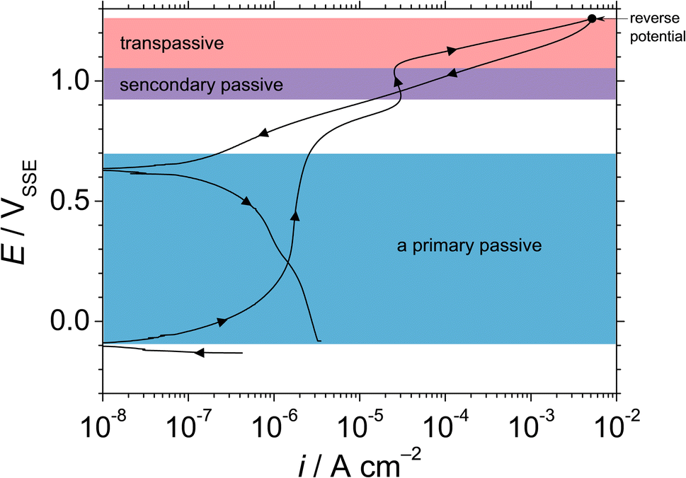
Fig. 1 shows the cyclic potentiodynamic polarisation curve of UNS N07718 in 5 wt% NaCl + 0.5 wt% CH3COOH. The alloy surface does not exhibit an active-to-passive transition, indicating that the surface is immediately passivated in the experimental solution. From the corrosion potential to 0.7 VSSE, the anodic current increases from ca. 0.01 μA cm−2 to reach a stable passive current density lower than ca. 2 μA cm−2. At potentials >0.7 VSSE, the anodic current increases and peaks ca. 30 μA cm−2 at 0.9 VSSE, which indicates further oxidation reactions on the alloy surface. These oxidation reactions reportedly represent secondary oxidation of metallic elements (Cr, Fe or Ni) or metal cations on the surface of Ni–Cr–Fe alloys in acidic solutions.23–25 At potentials >0.9 VSSE, the anodic current decreases owing to the secondary passivation of the alloy surface. At potentials >1.1 VSSE, the anodic current increases until 5 mA cm−2, then decreases to its value obtained at the applied potential and reverses negative potential direction towards the corrosion potential. During the reverse scan, the reverse curve intersects the forward curve at ca. 0.95 VSSE, which represents the repassivation potential for the secondary passivation on the alloy surface. Since the repassivation potential for the secondary passive state is higher than the primary passive region from the corrosion potential to ca. 0.7 VSSE, the UNS N07718 surface remained in a stable primary passive state without the passive film breakdown in the experimental solution.
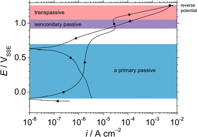 |
| | Fig. 1 Cyclic potentiodynamic polarisation curve of UNS N07718 in 5 wt% NaCl + 0.5 wt% CH3COOH. | |
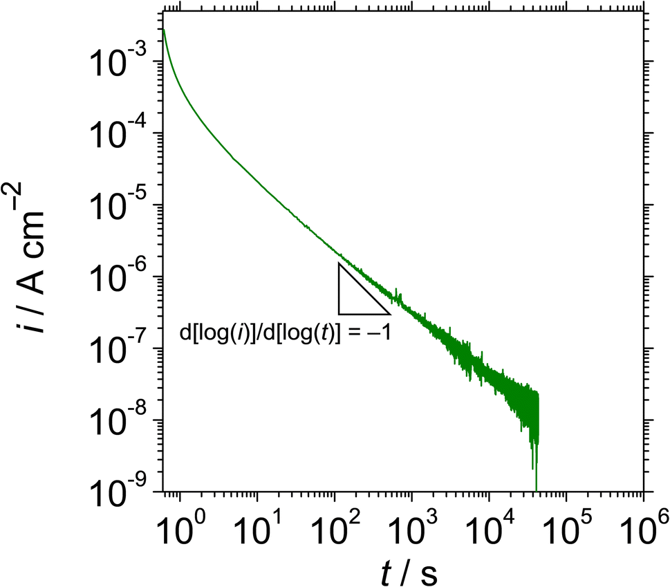
Fig. 2 shows the double logarithmic plot of current density with time at 0.5 VSSE for UNS N07718 in 5 wt% NaCl + 0.5 wt% CH3COOH. The current gradually decreases as the polarisation time increases, up to a slope of −0.85 for 10 s, demonstrating that the passive oxide grows through the consumption of the ionic current, based on the high-field mechanism,26 on the alloy surface. After 10 s of polarisation, the current decreases to <80 nA cm−2, and a slope of −0.85 is maintained for 43200 s, indicating that the passive oxide formation is sustained during the polarisation.
 |
| | Fig. 2 Double logarithmic plot of current density with time at 0.5 VSSE for UNS N07718 in 5 wt% NaCl + 0.5 wt% CH3COOH. | |
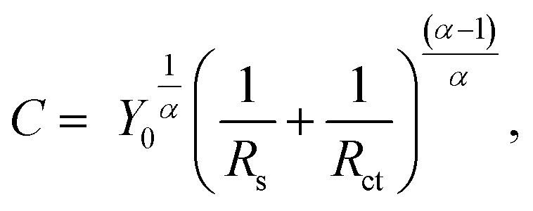
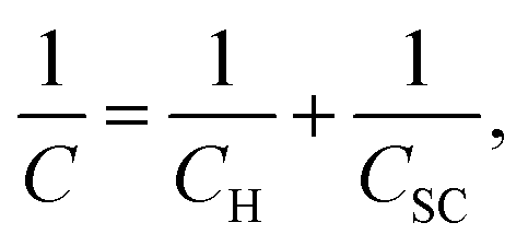
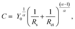
Fig. 3 shows (a) Bode and (b) Nyquist plots of UNS N07718 polarised at 0.5 VSSE for 300, 3600, 21600 and 43200 s in 5 wt% NaCl + 0.5 wt% CH3COOH. The resistance and phase shift values are fitted with the equivalent electronic circuit model, CPE-Rct–Rs, where CPE is the constant phase element, and Rct and Rs are the charge-transfer and solution resistances, respectively. The CPE is converted into interfacial capacitance C, which includes the capacitance of the Helmholtz and space-charge layers, by using the following equation:
| |
 | (1) |
where
Y0 is the CPE constant, and
α is the symmetric angle constant of the loop. The Kramer–Kronig transformation condition is satisfied at most frequencies. The Kramers–Kronig transformation is a mathematical relation between the imaginary and real components of responses obtained from a system that complies with certain assumptions. The relevant responses in EIS are the real and imaginary parts, or the phase and magnitude, of the impedance at a specific frequency. The real part can be calculated using Kramers–Kronig transformations if the imaginary part is known across the entire frequency range. Similarly, if the real part is known across the entire frequency range, it is possible to calculate the imaginary part. The phase shift values are close to −85° at a frequency lower than 100 Hz, indicating that the capacitive property of the alloy surface is dominant during the polarisation.
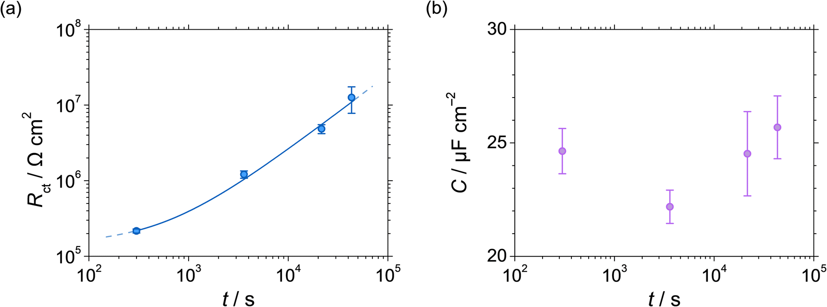
Rct increases, while
C is almost constant, during the polarisation, suggesting that the polarisation makes the alloy surface electrically resistive (
Fig. 4 and
Table 1).
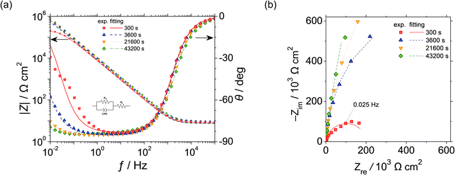 |
| | Fig. 3 (a) Bode and (b) Nyquist plots of UNS N07718 polarised at 0.5 VSSE for 300, 3600, 21600 and 43200 s in 5 wt% NaCl + 0.5 wt% CH3COOH. | |
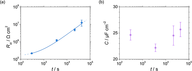 |
| | Fig. 4 (a) Charge-transfer resistance Rct and (b) capacitance C at 0.5 VSSE as functions of polarisation time of UNS N07718 in 5 wt% NaCl + 0.5 wt% CH3COOH. | |
Table 1 Parameters obtained by fitting the EIS spectra
| Polarisation time/s |
Rs/Ω cm2 |
Rct/106 Ω cm2 |
C/μF cm2 |
| 600 |
8.39 ± 0.19 |
0.22 ± 0.013 |
24.6 ± 1.00 |
| 3600 |
8.60 ± 0.83 |
1.21 ± 0.13 |
22.2 ± 0.73 |
| 21600 |
7.73 ± 0.97 |
4.85 ± 0.66 |
24.5 ± 1.86 |
| 43200 |
7.96 ± 0.69 |
12.6 ± 4.82 |
25.7 ± 1.39 |
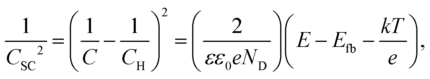
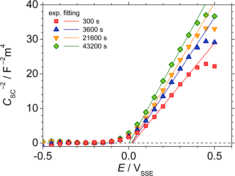
Fig. 5 shows the M–S plot of UNS N07718 polarised at 0.5 VSSE for 300, 3600, 21600 and 43200 s in 5 wt% NaCl + 0.5 wt% CH3COOH. The capacitance is obtained at a frequency of 10 Hz, as shown in Fig. 3, and includes the capacitances of the Helmholtz and space-charge layers:
| |
 | (2) |
where
CH and
CSC represent the capacitances of the Helmholtz and space-charge layers, respectively. Because the value of
CH is greater than that of
CSC,
C is close to
CSC. The M–S equation of a semiconductive oxide is expressed as follows:
| |
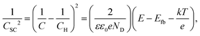 | (3) |
where
ε is the dielectric constant; for
n-type Cr hydroxides,
ε = 25;
27 ε0 is the permittivity constant in vacuum;
e is the charge value;
ND is the donor density;
Efb is the flatband potential;
k is Boltzmann's constant; and
T is the absolute temperature. A decrease in the capacitance at potentials >0.4 V
SSE is observed because of the accumulation of charge carriers due to the flow of a non-faradaic current during an electrical time delay before the initiation of the M–S measurements. A positive slope is observed at potential <0.4 V
SSE, indicating that the alloy surface has n-type semiconductive characteristics. In acidic solutions of Ni-based alloy
28 and pure Cr,
29 an n-type surface oxide layer is formed, suggesting that chromium hydroxide is formed on the surface. Moreover, the p-type property of the Cr-oxide layer formed on Fe–Cr alloys in acidic solutions is evident from the negative slope observed the M–S plot at a potential <0.5 V
SSE.
30,31 However, when the potential shifts to negative potential values, which are lower than the corrosion potential, the passive layer can be damaged by cathodic reactions, such as reduction in film thickness or mechanical degradation by hydrogen evolution on the surface. This potential shift implies that it is difficult to identify the p-type property of the UNS N07718 surface at potentials <−0.1 V
SSE. Therefore, in this study, the capacitance is measured in the potential range of 0.5 V
SSE to −0.5 V
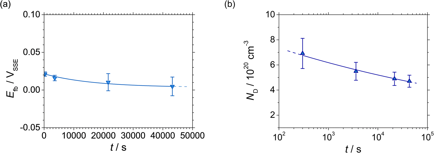
SSE. During the polarisation, the flatband potential (
Fig. 6(a)) shifts towards the negative direction, and the donor density decreases (
Fig. 6(b)), indicating that the passive oxide formed on the alloy surface becomes less defective.
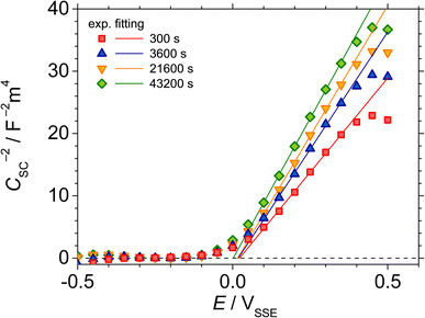 |
| | Fig. 5 M–S plots of UNS N07718 polarised at 0.5 VSSE for 300, 3600, 21600 and 43200 s in 5 wt% NaCl + 0.5 wt% CH3COOH. | |
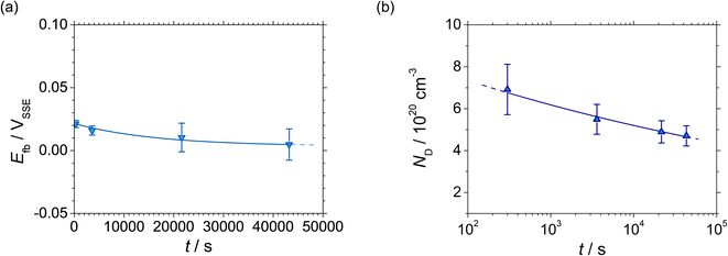 |
| | Fig. 6 (a) Flatband potential Efb, and (b) donor density ND at 0.5 VSSE as functions of polarisation time of UNS N07718 in 5 wt% NaCl + 0.5 wt% CH3COOH. | |
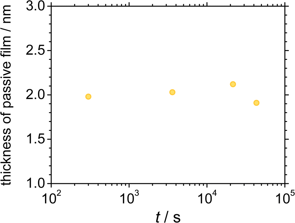
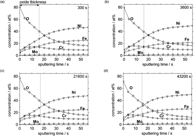
Fig. 7 shows the XPS depth profiles of the UNS N07718 surface polarised at 0.5 VSSE for (a) 300, (b) 3600, (c) 21600, and (d) 43200 s in 5 wt% NaCl + 0.5 wt% CH3COOH. The presence of O with a high atomic concentration at the outer layer indicates that the alloy surface was covered with an oxide layer. An interface transition can be assumed between the oxide and the metal substrate, with an O concentration that is half of that of the maximum O concentration. Based on this assumption, the passive oxide film thickness is estimated as ca. 2 nm based on the sputter rate of reference Ta2O5 for 0.125 nm s−1. Evidently, the atomic concentration of elemental Cr is higher than that of elemental Fe and Ni at the outermost layer of the film. The Cr atomic concentration is maximum at the interface between the oxide and the substrate and then gradually decreases, while that of Fe and Ni gradually increases as the sputtering time is increased. The photoelectron spectra obtained by X-ray irradiation contain depth information for a depth of ca. 2 nm on the surface, including that of the oxide film as well as the metallic substrate. As the sputtering time increases, the population of the photoelectrons emitted from the metallic state increase, suggesting that the photoelectrons emitted by O indicate the oxidation state of the oxide, and the thickness of the film can be estimated from this information. After each polarisation time, the XPS depth profiles corresponding to the atomic concentration show similar behaviours, indicating that the compositional ratios of the elements in the film remain similar. Fig. 8 shows the passive film thickness calculated from the XPS depth profiles of the alloy surface during the polarisation at 0.5 VSSE. The film thickness is almost constant at ca. 2 nm during the polarisation, indicating that the thickness of the passive film does not significantly change.
 |
| | Fig. 7 XPS depth profile of UNS N07718 polarised at 0.5 VSSE with polarisation time of (a) 300, (b) 3600, (c) 21600 and (d) 43200 s in 5 wt% NaCl + 0.5 wt% CH3COOH. | |
 |
| | Fig. 8 Estimated thickness of the passive film as a function of polarisation time at 0.5 VSSE. | |
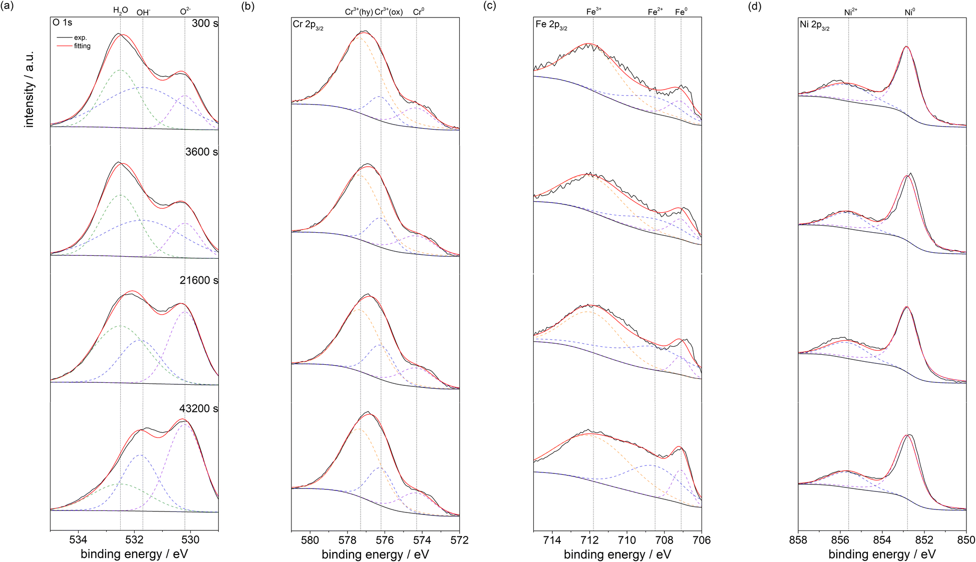
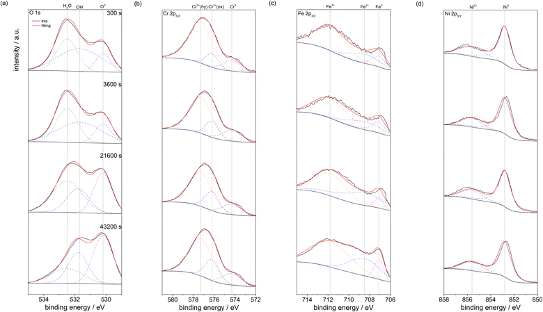
Fig. 9 shows the photoelectron spectra of (a) O 1s, (b) Cr 2p3/2, (c) Fe 2p3/2 and (d) Ni 2p3/2 for UNS N07718 polarised at 0.5 VSSE for 300, 3600, 21600, and 43200 s in 5 wt% NaCl + 0.5 wt% CH3COOH; in this case, the surface is not sputtered. The oxidation states of H2O, OH− and O2− for oxygen, those of Cr3+ (hydroxide), Cr3+(oxide) and Cr0 for chromium, those of Fe3+, Fe2+ and Fe0 for iron, and those of Ni2+ and Ni0 for nickel can be identified in the spectra. After Shirley background subtraction from narrow-scan spectra, the spectra are deconvoluted into individual spectrum corresponding to the oxidation states of oxygen, chromium, iron and nickel using the XPS peak binding energies shown in Table 2. The spectra of Mo 3d are not analysed owing to their low intensities. Because deconvoluting the spectrum of 2p orbital is complicated, in this study, the 2p3/2 spin data were used.
 |
| | Fig. 9 Photoelectron spectra of (a) O 1s, (b) Cr 2p3/2, (c) Fe 2p3/2 and (d) Ni 2p3/2 obtained for UNS N07718 polarised at 0.5 VSSE with polarisation time of 300, 3600, 21600 and 43200 s in 5 wt% NaCl + 0.5 wt% CH3COOH. | |
Table 2 Parameters for deconvolution of XPS spectra
| Element |
Peak |
Binding energy, eV |
Ref. |
| Fe |
2p3/2 |
Fe0 |
707.1 |
32 and 33 |
| Fe2+ |
708.5 |
34 and 35 |
| Fe3+ |
711.8 |
36 and 37 |
| Cr |
2p3/2 |
Cr0 |
574.3 |
38 and 39 |
| Cr3+(oxide) |
576.2 |
38–40 |
| Cr3+(hydroxide) |
577.3 |
38 and 39 |
| Ni |
2p3/2 |
Ni0 |
852.8 |
36 and 41 |
| |
Ni2+ |
855.6 |
37, 42 and 43 |
| O |
1s |
O2– |
530.2 |
35–39 |
| OH− |
531.7 |
36, 39 and 43 |
| H2O |
532.5 |
44 |
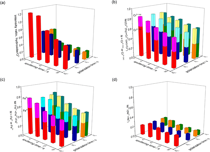
Fig. 10 shows the peak intensity ratios hydroxide/O2−; M/(Cr3+(hydroxide) + Cr3+(oxide) + Cr0), where M = Cr3+(hydroxide) or Cr3+(oxide); N/(Fe2+ + Fe3+ + Fe0), where N = Fe2+ or Fe3+; and Ni2+/(Ni2+ + Ni0) in each spectrum of the polarised surfaces. For all the polarisation durations of the surfaces (Fig. 10(a)), the hydroxide/O2− ratio is higher at the outermost layer of the film, and the ratio gradually decreases as the sputtering time increases. Further, the hydroxide/O2− ratio of the passive film decreases when the polarisation increases. It is presumed that the hydroxide layer is formed on the outermost layer of the passive film, and the hydroxide becomes an oxide in the film during the polarisation. The Cr3+(hydroxide)/(Cr3+ (hydroxide) + Cr3+(oxide) + Cr0) and Fe3+/(Fe2+ + Fe3+ + Fe0) ratios are higher than the Cr3+(oxide)/(Cr3+(hydroxide) + Cr3+(oxide) + Cr0) and Fe3+/(Fe2+ + Fe3+ + Fe0) ratios at the outermost layer of the film, while the Cr3+(hydroxide)/(Cr3+ (hydroxide)+Cr3+(oxide)+Cr0) and Fe3+/(Fe2+ + Fe3+ + Fe0) ratios decrease with the sputtering time. Moreover, the Cr3+(hydroxide)/(Cr3+(hydroxide) + Cr3+(oxide) + Cr0) and Fe3+/(Fe2+ + Fe3+ + Fe0) ratios gradually decrease in the film with the increasing polarisation time (Fig. 10(b) and (c)). The Ni0/(Ni2+ + Ni0) ratio is greater than Ni2+/(Ni2+ + Ni0) ratio irrespective of the polarisation time (Fig. 10(d)), indicating that the Ni cation is a minor component in the passive film.
 |
| | Fig. 10 Peak intensity ratio of the oxidation states of the elements (a) O (b) Cr (c) Fe and (d) Ni, present in the passive film, as a function of polarisation time. | |
The XPS results reveal that the passive film formed on UNS N07718 is composed of a Cr-(hydro)oxide and Fe-oxide layer followed by an outer and inner layer enriched with Cr-hydro/oxide and Fe oxide, respectively. During the ageing, the Cr hydroxide in the outer layer of the film changes to a Cr-oxide layer, while the thickness of the film is almost constant at ca. 2 nm (Fig. 11). Elemental Cr is reportedly enriched in the passive film formed on the additively-manufactured UNS N07718 surface in sulfuric acid.2 However, the structure of the oxide layer as the inner (or outer) layer of the film has not been elucidated.
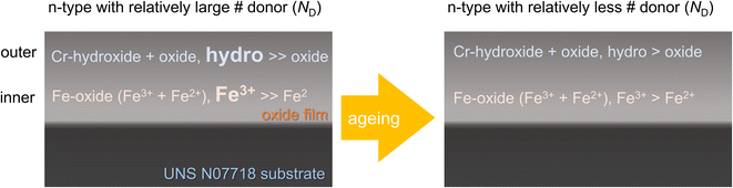 |
| | Fig. 11 Schematic illustration for the ageing of passive film formed on UNS N07718. | |
The passive film formed on UNS N07718 becomes electrically resistive with a decrease in the defect density during the polarisation. The film exhibits n-type characteristics with a space-charge layer thickness of <1 nm, as evident from the M–S plot. This result is obtained by assuming that the semiconductive property, revealed from the electrochemical experiments, is strongly related to the Cr hydro/oxide and Fe oxide in the film. Since n-type semiconductors contain defects such as metal cationic interstitials and oxygen vacancies, the decrease in the defect density during the polarisation is believed to be mainly associated with the increase in the oxide concentration in the film:
where M is a metal (Cr, Fe or Ni). During the polarisation, the dehydrated oxide layer, without the growth of the film, becomes electrochemically less reactive.
For Fe–Cr–Ni alloys, the passive film contains Fe oxide and Cr oxide at the outer and inner layers.18–20 When the film comes in contact with Cl−, Cl− is adsorbed on the Fe-oxide layer of the film, and Fe–Cl complexes are formed. The complex dissolves in the solution, and the film becomes thin. This phenomenon is known as the adsorption mechanism, which degrades the passive film.44 Recently, Auger spectroscopic results have revealed that the thickness of a passive film formed on austenitic stainless steel decreases significantly in a concentrated Cl− solution. The thinned film accelerates additional charge transfer from the surface states to the metallic substrate through the n-type conduction band edge of the film.45 Compared with Fe-based alloys, Ni-based alloys are more resistant to localised corrosion in chloride-containing environments. The findings of the present study demonstrate that the passive film formed on the UNS N07718 surface has Cr oxide and Fe oxide in its outer and inner layers. When UNS N07718 comes in contact with Cl−, Cr–Cl complexes might form because of the adsorption of Cl− on the Cr-oxide layer. These Cr–Cl complexes are insoluble, while the Fe–Cl complexes, i.e. FeCl2 and FeCl3, are soluble; up to 65.0 g of FeCl2 and 91.2 g of FeCl3 can be completely dissolved in 0.1 L of water.46 It is speculated that the film formed on the UNS N07718 surface, enriched in Cr oxide at the outer layer, suppresses the degradation of the film in Cl-containing solutions, and this minimised degradation is related to the localised corrosion resistance of UNS N07718.
4. Conclusion
The ageing of the passive film on UNS N07718 was investigated in a shallow sour condition of 5 wt% NaCl + 0.5 wt% CH3COOH. The UNS N07718 surface was in a passive state during polarisation at 0.5 VSSE in the solution for 12 h, and the passive film formed on the alloy became relatively stable owing to the formation of an electrochemically resistive n-type oxide layer with less defects. XPS analysis revealed that the film comprised Cr- and Fe-enriched hydro/oxide outer and inner layers. Moreover, the film sustained its thickness at ca. 2 nm during the polarisation, while the outer Cr-hydroxide layer changed into a Cr-oxide layer. The first investigation of the passivation behaviour of UNS N07718 over polarisation time revealed that the passive surface maintained its passive state during the polarisation because the dehydrated oxide layer produced during the polarisation could change into a resistive and less-defective passive film.
Author contributions
Jun-Seob Lee: conceptualization; formal analysis; funding acquisition; investigation; methodology; project administration; supervision; Validation; Writing – original draft; writing – review & editing, Ye-Jin Lee: methodology; data curation; formal analysis; validation, Soon il Kwon: data curation; resources, Jungho Shin: resources; project administration, Sung Kang: data curation, funding acquisition; Seung-Hoon Baek: data curation; formal analysis, Je-Hyun Lee: project administration; funding acquisition.
Conflicts of interest
There are no conflicts to declare.
Acknowledgements
This research was supported by Basic Science Research Program through the National Research Foundation of Korea (NRF) funded by the Ministry of Education (No. NRF-2019R1I1A3A010409902019-0249). This work was supported by Korea Institute of Energy Technology Evaluation and Planning (KETEP) grant funded by the Korea government (MOTIE) (20214000000480, Development of R&D engineers for combined cycle power plant technologies).
References
- C.-M. Kuo, Y.-T. Yang, H.-Y. Bor, C.-N. Wei and C.-C. Tai, Mater. Sci. Eng., 2009, 510, 289 CrossRef
 .
. - L. N. Zhang and O. A. Ojo, J. Alloys Compd., 2020, 829, 154455 CrossRef CAS .
- B. Zhang, M. Xiu, Y. T. Tan, J. Wei and P. Wang, Appl. Surf. Sci., 2019, 490, 556 CrossRef CAS .
- H. S. Klapper and J. Stevens, Corrosion, 2014, 70, 899 CrossRef PubMed .
- Z. F. Yin, W. Z. Zhao, W. Y. Lai and X. H. Zhao, Corros. Sci., 2009, 51, 1702 CrossRef CAS .
- U. Martin, J. Ress, J. Bosch and D. M. Bastidas, Metals, 2020, 10, 204 CrossRef CAS .
- G. A. Rao, M. Kumar, M. Srinivas and D. S. Sarma, Mater. Sci. Eng. A, 2003, 355, 114 CrossRef .
- X. L. An, L. Zhou, B. Zhang, J. J., C. L. Chu, L. Y. Han, H. G. Y. and P. K. Chu, Mater. Res. Express, 2019, 6, 075803 CrossRef CAS .
- S. Luo, W. Huang, H. Yang, J. Yang, Z. Wang and X. Zeng, Addit. Manuf., 2019, 30, 100875 CAS .
- M. Amirjan, M. Bozorg and H. Sakiani, Mater. Chem. Phys., 2021, 263, 124368 CrossRef CAS .
- S. Fujimoto, T. Yamada and T. Shibata, J. Electrochem. Soc., 1998, 145, L79 CrossRef CAS .
- H. Saito, T. Shibata and G. Okamoto, Corros. Sci., 1979, 19, 693 CrossRef CAS .
- K. Sugimoto, S. Matsuda, Y. Ogiwara and K. Kitamura, J. Electrochem. Soc., 1985, 132, 1791 CrossRef CAS .
- V. Vignal, H. Krawiec, O. Heintz and D. Mainy, Corros. Sci., 2013, 67, 109 CrossRef CAS .
- T. Ohtsuka, M. Ueda and M. Abe, J. Electrochem. Soc., 2016, 163, C459 CrossRef CAS .
- M. E. Curley-Fiorino and G. M. Schmid, Corros. Sci., 1980, 20, 313 CrossRef CAS .
- K. Oh, S. Ahn, K. Eom, K. Jung and H. Kwon, Corros. Sci., 2014, 79, 34 CrossRef CAS .
- R. Devaux, D. Vouagner, A. M. D. Becdelievre and C. Duret-Thual, Corros. Sci., 1994, 36, 11 CrossRef .
- V. Vignal, H. Zhang, O. Delrue, O. Heintz, I. Popa and J. Peultier, Corros. Sci., 2011, 53, 894 CrossRef CAS .
- Z. Wang, A. Seyeux, S. Zanna, V. Maurice and P. Marcus, Electrochim. Acta, 2020, 329, 135159 CrossRef CAS .
- Y. Qiao, X. Wang, L. Yang, X. Wang, J. Chen, Z. Wang, H. Zhou, J. Zou and F. Wang, J. Mater. Sci. Technol., 2022, 107, 197 CrossRef .
- Y. Zhang, J. Yu, X. L. P. Guo, X. Yu, S. Zhang, J. Liu and W. Huang, Corros. Sci., 2022, 205, 110439 CrossRef CAS .
- J. R. Myers, F. H. Beck and M. G. Fontana, Corrosion, 1956, 21, 277 CrossRef .
- M. Bojinov, I. Betova, G. Fabricius, T. Laitinen, R. Raicheff and T. Saario, Corros. Sci., 1999, 41, 1557 CrossRef CAS .
- C. T. Liu and J. K. Wu, Corros. Sci., 2007, 49, 2198 CrossRef CAS .
- N. Cabrera and N. F. Mott, Rep. Prog. Phys., 1949, 12, 163 CrossRef CAS .
- T. P. Moffat and R. M. Latanision, J. Electrochem. Soc., 1992, 130, 1869 CrossRef .
- J.-S. Lee and R. Bäßler, Corros. Eng., Sci., 2018, 53, 302 CrossRef CAS .
- Ž. Petrović, N. Lajçi, M. Metikoš-Huković and R. Babić, J. Solid State Electrochem., 2011, 15, 1201 CrossRef .
- N. Zakerin and K. Morshed-Behbahani, Metall. Mater. Trans. A, 2021, 52, 3247 CrossRef CAS .
- J. Huang, X. Wu and E.-H. Han, Corros. Sci., 2009, 51, 2976 CrossRef CAS .
- A. S. Lim and A. Atrens, Appl. Phys. A, 1990, 51, 411 CrossRef .
- R. Idczak, K. Idczak and R. Konieczny, Corrosion, 2018, 74, 623 CrossRef CAS PubMed .
- N. S. McIntyre and D. G. Zetaruk, Anal. Chem., 1977, 49, 1521 CrossRef CAS .
- T. L. Barr, J. Phys. Chem., 1978, 82, 1801 CrossRef CAS .
- J. Chastain, and R. C. King Jr, Handbook of X-ray photoelectron spectroscopy, Perkin-Elmer Corporation, 1992, vol. 40, p. 221 Search PubMed .
- B. Stypula and J. Stoch, Corros. Sci., 1994, 36, 2159 CrossRef CAS .
- M. C. Biesinger, C. Brown, J. R. Mycroft, R. D. Davidson and N. S. McIntyre, Surf. Interface Anal., 2004, 36, 1550 CrossRef CAS .
- A. Lebugle, U. Axelsson, R. Nyholm and N. Mårtensson, Phys. Scr., 1981, 23, 825 CrossRef CAS .
- I. Olefjord, B. Brox and U. Jelvestam, J. Electrochem. Soc., 1985, 132, 2854 CrossRef CAS .
- N. S. McIntyre and M. G. Cook, Anal. Chem., 1975, 47, 2208 CrossRef CAS .
- C. E. Dubé, B. Workie, S. P. Kounaves, A. Robbat Jr, M. L. Aksub and G. Davies, J. Electrochem. Soc., 1995, 142, 3357 CrossRef .
- S. Jin and A. Atrens, Appl. Phys. A, 1987, 42, 149 CrossRef .
- J. M. Kolotyrkin, Corrosion, 1963, 19, 261t CrossRef .
- J.-S. Lee, T. Kawano, T. Ishii, Y. Kitagawa, T. Nakanishi, Y. Hasegawa and K. Fushimi, J. Electrochem. Soc., 2017, 164, C1 CrossRef CAS .
- D. R. Lide, CRC Handbook of Chemistry and Physics, CRC Press, Boca Raton, 9th edn, 2010, vol. 4, pp. 58–69 Search PubMed .
|
| This journal is © The Royal Society of Chemistry 2023 |
Click here to see how this site uses Cookies. View our privacy policy here. 
 Open Access Article
 This Open Access Article is licensed under a Creative Commons Attribution-Non Commercial 3.0 Unported Licence
 *ab,
Ye-Jin Leeb,
Soon il Kwonc,
Jungho Shinc,
Sung Kangd,
Seung-Hoon Baekd and
Je-Hyun Leeab
*ab,
Ye-Jin Leeb,
Soon il Kwonc,
Jungho Shinc,
Sung Kangd,
Seung-Hoon Baekd and
Je-Hyun Leeab