 Open Access Article
Preferential dissolution behaviour of the austenite phase in Fe–27Cr–xC high chromium cast iron
Jun-Seob Lee *ab,
Jun-Hyeong Leebc,
Seo-Young Rhob,
Yoon-Hwa Leeb,
Ye-Jin Leeb,
Jun-Seok Ohad and
Je-Hyun Leeab
aSchool of Materials Science and Engineering, Changwon National University, Changwondaehak-ro, Changwon, 51140, South Korea. E-mail: junseoblee@changwon.ac.kr; Fax: +82-55-261-7017; Tel: +82-55-213-3691
bDepartment of Materials Convergence and System Engineering, Changwon National University, Changwondaehak-ro, Changwon, 51140, South Korea
cCOTEC, Ungnam-ro, Changwon, 51553, South Korea
di-Casting Tech Ltd., Gomo-ro, Gimhae, 50875, South Korea
First published on 26th June 2023
Abstract
Preferential dissolution behaviour of the austenite (γ) phase in Fe–27Cr–xC high chromium cast irons (HCCIs) immersed in 0.1 mol dm−3 H2SO4 + 0.05 mol dm−3 HCl was investigated. Potentiodynamic and potentiostatic polarisation revealed that the primary and eutectic γ phases dissolved preferentially at –0.35 and 0.00 VSilver Silverchloride Electrode potential in sat. KCl (SSE), respectively. The immersion of the HCCIs in the solution showed that the dissolution of the primary γ phase dominated for ca. 1 h, while the primary and eutectic γ phases dissolved after ca. 1 h. However, the carbide phases remained undissolved during the dissolution of the γ phases. Furthermore, the corrosion rate of the HCCIs increased with the increasing C content owing to the increase in the contact potential difference values of the γ and carbide phases. The change in electromotive force due to C addition was related to the accelerated corrosion rate of the γ phases.
1. Introduction
Cast iron, containing 2.0 to 3.0 wt% of carbon and 14.0 to 28.0 wt% of chromium as its main alloying elements, is known as high chromium cast iron (HCCI). Because of its higher C and Cr contents compared to that of carbon steel and stainless steel, respectively, HCCI is more resistant to corrosion and wear in acoustic environments, such as acidic chloride environments. As a result, HCCI is widely applied in the rolls, moulds, and slurry pumps in flue gas desulphurization (FGD) facilities.1–5 Although various types of HCCIs are employed in the slurry pumps used in FGD plants, HCCIs with 27 wt% of Cr are preferred, because their corrosion resistance is higher than that of the other HCCIs.2,6–11 The alloys used in the FGD systems frequently experience localised corrosion, stress corrosion cracking, or general corrosion in highly corrosive environments like acidic chloride solutions. It was considered that experimental solutions were simulated as a mixture of sulfuric and hydrochloric acids as representatives of a corrosive environment for FGD facilities.12–14Hypoeutectic HCCI (<3.0 wt% of C) comprises eutectic γ and carbide (mainly M7C3) phases as well as a dendritic primary γ phase.3,15 The fractions of the carbide and γ phases influence the mechanical properties and corrosion resistance of the HCCI. In particular, C, one of the main alloying elements of HCCIs, affects the fractions of the carbide and γ phases in HCCIs.3,15,16 The relation between the γ and carbide phases plays an important role in the corrosion behaviour of HCCI. For example, the anodic reaction at the γ phase or that at the interface between the carbide and γ phases is accelerated by the carbide phase, which, in contrast to the γ phase, typically acts as a local cathode in the HCCI.8,11,17
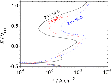
In our previous study, the HCCI 27Cr–x(2.1 wt% < x < 2.8 wt%)C exhibited both primary and eutectic γ with carbide phases. The phase fractions of γ and carbide can be significantly affected by changing the composition of the main alloying element, i.e. C.18,19 Increasing the C content in the HCCI decreases the fraction of γ, while the carbide phase fraction increases. Moreover, it was the first report that the active dissolution of the primary and eutectic γ in the HCCI was revealed by two designated peaks observed in the active-state potentiodynamic polarisation curves obtained in 0.1 mol dm−3 H2SO4 + 0.05 mol dm−3 HCl (Fig. 1 (ref. 18)). The first and second peaks at the potential of approximately −0.35 and 0.1 VSSE were related to the preferential dissolution of the primary and eutectic γ phases, respectively. The carbide phase did not dissolve during the polarisation, irrespective of the C addition in the HCCI. The carbide phase acted as a cathode, whereas the γ (primary and eutectic) phases functioned as the anode, indicating that the galvanic dissolution of the γ phases is important to understand the general corrosion of HCCIs. When the C content in the HCCIs increases, the chemical composition and fraction of the comprised phases change.19 Galvanic dissolution may accelerate the preferential dissolution of the γ phases in the HCCIs. It is important to explore the preferential dissolution of austenite phases in the HCCI to elucidate the initiation behaviour of corrosion which can trigger the propagation of localised or stress corrosion cracking in the FGD environments. However, the preferential dissolution behaviour of the γ phases in Fe–27Cr–xC HCCIs with time remains hitherto unexplored.
This study investigated the preferential dissolution of the γ phases in the HCCIs during immersion in an acidic solution. The effect of C addition on the corrosion behaviour of the HCCI was evaluated as well.
2. Experimental procedures
The HCCI specimens were prepared with a chemical composition of 2.1, 2.4 and 2.8 wt% of C with 27 wt% of Cr balanced with Fe. Induction-melted HCCI rods of 13 mm diameter were cut into 5 mm-thick specimens and ground with SiC papers down to 3000 grit.The identification of crystallographic phases was conducted using an electron-backscattered diffraction (EBSD) pattern using a scanning electron microscope (JSM-6510, JEOL). A database of crystallographic models was used to approximate the diffraction patterns. Additionally, phase fractions were obtained from colour images of the HCCI surfaces analyzed by an image analyzer.
The electrochemical measurements were performed using a three-electrode system in 0.1 mol dm−3 H2SO4 + 0.05 mol dm−3 HCl at room temperature. The HCCI specimens, with a surface area of 1.13 cm2, were used as the working electrode. The reference electrode was Ag/AgCl filled with saturated KCl (silver–silver chloride electrode; SSE), and glassy carbon with a surface area of 18 cm2 was used as the counter electrode. The transient electrode potential was monitored in 0.1 mol dm−3 H2SO4 + 0.05 mol dm−3 HCl for 24 h.
The HCCI specimens were also immersed in the 0.1 mol dm−3 H2SO4 + 0.05 mol dm−3 HCl solution for 24 h. Then, all the specimens were ultrasonically rinsed with deionized water, ethanol, and acetone for 5 min after specific immersion times of 0.16, 0.50, 1, 2, 3, 6, 12 and 24 h. Subsequently, the weights of the specimens were measured, and finally, the surfaces of the HCCI specimens were observed using an optical microscope.
Scanning Kelvin Probe Force Microscopy (SKPFM) was performed using a commercial atomic force microscope (XE-100, Park Systems), working in the electrostatic force microscope mode in air at room temperature. A conductive cantilever (NSC36-A, Park Systems) with a Cr/Au coat, resonance frequency of 25–115 kHz and spring constant of 0.06–2.7 N m−1 was used. The scans were performed over an area of 30 × 30 μm2 with a scan rate of 0.1 Hz.
3. Results
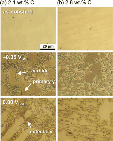
Fig. 1 shows the potentiodynamic polarisation curves of the Fe–27Cr–xC HCCIs with different C contents of 2.1, 2.4 and 2.8 wt%. An active-to-passive transition behaviour is evident for the corrosion potential up to approximately 0.2 VSSE. As the C content increases in the HCCIs, the corrosion potential shifts in a more noble direction, from –0.421 to –0.410 VSSE, and the corrosion current density decreases from 1.4 × 10⁻³ to 0.6 × 10⁻³ A cm−2. In addition, active regions with critical current densities are observed in the two regions from ca. –0.40 VSSE or ca. 0.00 to 0.20 VSSE. In the active region, the critical current density at potential ca. –0.3 VSSE decreases, while the critical current density at potential ca. 0.1 VSSE increases with an increase in C content in the HCCIs. The anodic current decreases at the potential range from ca. 0.20 to 0.50 VSSE, and the HCCI surfaces exhibit a passive state. In the passive region, the passive current density increases from 4.3 × 10⁻⁴ to 2.6 × 10⁻³ A cm−2 with an increase in C content in the HCCIs. At potentials >0.50 VSSE, the anodic current sharply increases with the polarisation, indicating the transpassive behaviour of the HCCI.Fig. 2 presents the optical microscopic images of the Fe–27Cr–xC HCCI surfaces with different C contents of (a) 2.1 and (b) 2.8 wt% before and after the potentiostatic polarisation at –0.35 or 0.00 VSSE, respectively, for 0.16 h. The applied potentials, –0.35 and 0.00 VSSE, correspond to the anodic dissolution peaks observed in Fig. 1. Irrespective of the C content in the HCCIs, the dissolution behaviour dominates in the primary or the eutectic γ phase at –0.35 or 0.00 VSSE, respectively. This preferential dissolution behaviour is associated with the two active dissolution peaks in the potentiodynamic polarisation curves. These peak current densities change as the fractions and chemical compositions of the primary and eutectic γ phases change with the C content in the HCCI.
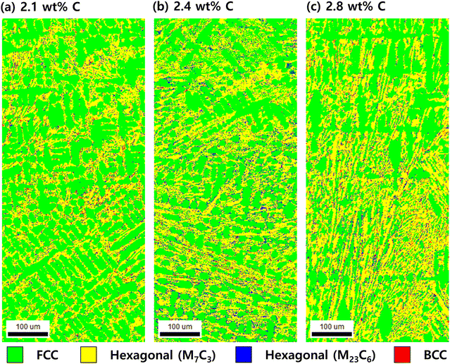
Fig. 3 shows EBSD phase map images of the Fe–27Cr–xC HCCIs before the polarisation. The green phase represents face-centred cubic (FCC), the yellow phase represents hexagonal (M7C3; M = Fe and Cr), the navy blue phase represents hexagonal (M23C6), and the red phase represents the crystal structure of body-centred cubic (BCC) or body centred tetragonal (BCT). The FCC is identified as the austenite phase, hexagonal as carbides, and BCC/BCT as either ferrite or martensite. Regardless of the C content, the microstructure of the HCCIs consists of primary γ phase with dendritic or cellular morphology, eutectic γ phase, hexagonal carbide phase, and ferrite or martensite phase. As the C content increases from 2.1 wt% to 2.8 wt%, the proportion of γ phase decreases from 59.4% to 46.6%, while the proportion of carbide phase (M7C3) increases from 38.1% to 51.9%. On the other hand, the proportion of ferrite or martensite phase does not show a significant difference depending on the C content. The proportion of the dendritic phase decreases as the C content of HCCI increases, while the proportion of the non-dendritic γ phase increases with an increase in C content. Since it is difficult to distinguish between BCC and BCT structures from the EBSD phase map, the proportions of ferrite and martensite phases were not separately distinguished.
Fig. 4 shows the transient electrode potentials, during the open circuit condition of the HCCI electrodes with the C contents of 2.1, 2.4 and 2.8 wt%, observed for 24 h in 0.1 mol dm−3 H2SO4 + 0.05 mol dm−3 HCl. The potential values rise sharply from ca. –0.36 to –0.30 VSSE in the initial stage for 1 h and then gradually shift towards a positive potential direction to ca. –0.26 VSSE for 24 h. Since the active dissolution of austenite phases in the HCCIs occurs at the potential range from ca. –0.40 to 0.20 VSSE, as shown in Fig. 1, the HCCIs experience active dissolution during their immersion for 24 h, irrespective of the C content in the HCCIs.
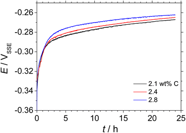 | ||
| Fig. 4 Transient of electrode potential for the Fe–27Cr–xC HCCI: x = 2.1 wt%, 2.4 wt% and 2.8 wt%. For this analysis, the HCCIs were immersed in 0.1 mol dm−3 H2SO4 + 0.05 mol dm−3 HCl for 24 h. | ||
Fig. 5 demonstrates the changes in the corrosion rates of the Fe–27Cr–xC HCCIs, with C contents of 2.1, 2.4 and 2.8 wt%, in 0.1 mol dm−3 H2SO4 + 0.05 mol dm−3 HCl for 0.16, 0.50, 1, 2, 3, 6 and 24 h. The corrosion rate is determined based on the weight loss of the HCCIs after immersion for a specific time as follows:
 | (1) |
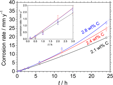 | ||
| Fig. 5 Corrosion rates of the Fe–27Cr–xC HCCIs immersion for 24 h in 0.1 mol dm−3 H2SO4 + 0.05 mol dm−3 HCl: x = 2.1 wt%, 2.4 wt% and 2.8 wt%. | ||
Fig. 6 shows the optical microscopic images of the Fe–27Cr–xC HCCI surfaces, with different C contents of (a) 2.1 and (b) 2.8 wt%, after 0.16, 1, 2, 3, 6 and 24 h of immersion in 0.1 mol dm−3 H2SO4 + 0.05 mol dm−3 HCl. A previous study suggested that the microstructure of the HCCIs consists of dendritic primary γ with eutectic γ and carbide phases.15,18,20 After the initial 0.16 h of immersion, the phase boundary between γ and the carbide is etched, and the γ phases are slightly corroded. The dendritic primary γ phase dissolves after 1 h of immersion, whereas the eutectic γ (interspace between the carbide phase) phase dissolves after 2 h. Beyond 2 h, except the carbide phase, the γ phases are completely dissolved. Finally, only the carbide phase remains after 24 h of immersion. This dissolution progress indicates the preferential dissolution of the primary γ phase rather than the eutectic γ. Further, the carbide phase acts as a relatively inert area during the active dissolution in the acidic solution.
 | ||
| Fig. 6 Optical microscopic images of the Fe–27Cr–xC HCCIs obtained after immersion for 0.16, 1, 2, 3, 6 and 24 h in 0.1 mol dm−3 H2SO4 + 0.05 mol dm−3 HCl: x = (a) 2.1 wt% and (b) 2.8 wt%. | ||
Fig. 7 displays the (a) topography and (b) contact potential difference (CPD) images obtained by SKPFM as well as the (c) height and (d) CPD profiles with varying scanning distances on the as-polished the HCCIs with C content of (a and c) 2.1 and (b and d) 2.8 wt%. The carbide phases protrude from the surface of the polished specimens depending on the difference between the hardness of the carbides and substrate (Fig. 7(a) and (c)). The CPD between the cantilever tip and the substrate is higher at the carbides than at the substrate. The CPD values of the primary γ phase are lower than that of the eutectic γ phases (Fig. 7(d)), irrespective of the C content in the HCCIs. The relative CPDs of the primary γ, i.e., ΔmV/Vprimary γ, are in the order of carbide > eutectic γ > primary γ, irrespective of the C content in the HCCIs (Fig. 8). This result implies that the electrochemical nobility is in the order of carbide > eutectic γ > primary γ. As the C content increases in the HCCI, the ΔmV/Vprimary γ values of the eutectic and carbide phases increase from 4.0 to 10.3 and from 12.3 to 37.9, respectively, considering that the C addition in the HCCI changes the electrochemical nobility of both the carbide and γ phases.
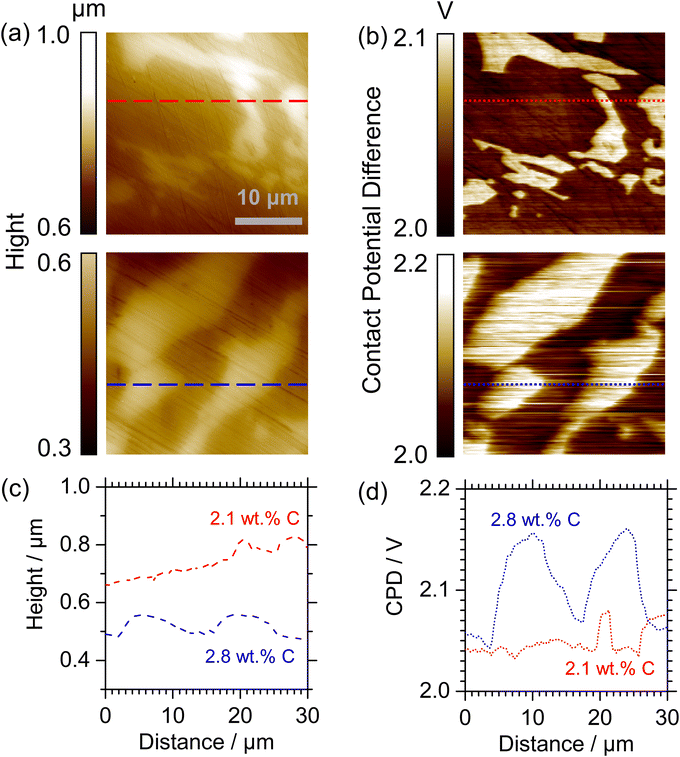 | ||
| Fig. 7 (a) Topography and (b) CPD images; (c) height and (d) CPD profiles at different distances on the Fe–27Cr–xC HCCI with x = 2.1 wt% and 2.8 wt%. | ||
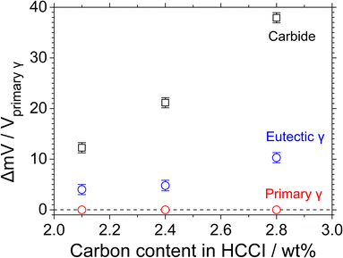 | ||
| Fig. 8 Relative CPDs with respect to the primary γ phase for the Fe–27Cr–xC HCCIs with x = 2.1 wt%, 2.4 wt% and 2.8 wt%. | ||
4. Discussion
The Fe–27Cr–xC HCCIs investigated in this study are composed of γ and carbide phases. The preferential dissolution behaviour of the primary and eutectic γ phases are determined from the potentiostatic polarisation curves at –0.35 and 0.00 VSSE, respectively. Because the primary and eutectic γ dominantly dissolve at the electrode potential range from ca. –0.40 to ca. –0.30 VSSE and from ca. –0.30 to ca. 0.10 VSSE (Fig. 1), respectively, the primary γ phase in the HCCIs actively dissolve after immersion for 1 h (Fig. 6). This result can be attributed to the change in the electrode potential of the HCCIs from –0.36 to –0.29 VSSE. After immersion for 1 to 24 h, when the electrode potential of the HCCIs shifts from –0.30 to –0.26 VSSE, the eutectic γ phase also dissolves, whereas the carbide phase sustains without undergoing active dissolution. When the C content increases in the HCCIs, the corrosion rate increases (Fig. 5), because the decrease in the volume fraction of the γ phase15,18,20 accelerates the preferential dissolution rate of the γ in the HCCI.According to a previous study, when C is added to the Fe–27Cr–xC HCCIs, the Cr/Fe ratio of the γ phase decreases from 0.247 to 0.206 and that of the carbide phase decreases from 3.04 to 2.23. In contrast, the M (Fe and Cr)/C ratio of the γ phase decreases from 26.8 to 22.8, whereas that of the carbide phase remains almost constant.20 The C–Fe atomic bond is less covalent (more ionic) than the C–Cr bond in both the γ and carbide phases in the HCCIs.21,22 As a result, the decrease in the Cr/Fe ratio of the phases leads to the strengthening of both the metallic and ionic C–M bonds in the γ and carbide phases. Although the metallic bond is relatively weaker than the ionic and covalent bonds, the metallic bond strength is strongly associated with the electron work function (EWF).21,22 High electron densities between metal atoms lead to high metallic bond strengths, which are related to high EWF values. When the C content is increased in the HCCIs, the CPD values increase owing to the increase in the metallicity of both the γ and carbide phases (Fig. 8).
On the one hand, the CPD, ΔmV/Vprimary γ, values of the γ and carbide phases increase with the increasing C addition in the HCCIs, because the electrochemical nobility difference between the cathode and the anode also increases. A high electrochemical nobility difference between these phases generates a high electrochemical motive force difference between the cathode and the anode, resulting in an increased local-galvanic current between the electrodes. Finally, the increase in the local galvanic current accelerates the dissolution of the γ phases in the HCCIs.
On the other hand, the change in the CPD, expressed as ΔmV/Vprimary γ shows an increase in γ phases as C addition in the HCCIs increases. It is reported that the anodic dissolution rate is strongly related to the EWF, which involves the ionisation energies (work functions) of atoms in the alloys.23 Kadowai et al. reported that the anodic dissolution was suppressed when C was added to martensitic steel in acid solutions.24 Since the C addition in the HCCIs decreases the EWF in the γ phases, the anodic dissolutions of the γ phase increase.
In our previous study, the passivity of the HCCIs was strongly associated with the C addition in the HCCIs. Electrochemical and surface investigations demonstrated that incorporating C in the HCCI led to higher defect densities in the semiconductive oxide layers, specifically the n-type and p-type, associated with the austenite and carbide phases, respectively.20 The potentiodynamic polarisation (Fig. 1) of the HCCI in this study also revealed that the passivated surfaces of the HCCIs become conductive by the C addition in the HCCIs.
This study focused on the preferential dissolution behaviour of the γ phase with increasing C content in the HCCIs. This preferential dissolution behaviour was evaluated via time-dependent immersion and surface analyses of the γ and carbide phases. Previous studies were focused on the localized or tribological corrosion behaviour of HCCIs in certain corrosive media.1,2,5,8 To the best of the authors' knowledge, this is the first report on the preferential corrosion behaviour of γ phases in HCCIs. In particular, this study is the first approach to elucidate the preferential dissolution of the γ phase in terms of CPD changes with C addition in the HCCIs. In future studies, we will fabricate an independent single-phase (carbide or γ phase) electrode to precisely calculate the preferential corrosion rate of the γ phase. The galvanic corrosion effect between the two phases will be reported in the near future.
5. Conclusions
We investigated the preferential dissolution behaviour of the γ phase in Fe–27Cr–xC HCCIs for different immersion times in an acidic chloride solution. The potentiodynamic polarisation curves of the HCCIs at −0.35 and 0.00 VSSE indicated the preferential dissolution of the primary and eutectic γ phases, respectively. Immersion in the acidic solution for 24 h confirmed that the primary γ phase preferentially dissolved at ca. 1 h. After ca. 1 h, both the eutectic and primary γ phases dissolved, while the carbide phases remained without dissolution. As the C content increased in the HCCIs, the dissolution rate of the HCCIs increased. The SKPFM analysis revealed that the CPD values of the phases in the HCCI are in the order of primary γ < eutectic γ < carbide phases. The addition of C in the HCCIs changed the CPD values of the phases in the HCCIs. This result can be attributed to the strong correlation between the CPD values and the atomic bonding strengths of the Fe–C and Cr–C bonds of the γ and carbide phases. Because of this strong correlation, the galvanic corrosion of the γ phases in the HCCIs is accelerated.Author contributions
Jun-Seob Lee: conceptualization; formal analysis; funding acquisition; investigation; methodology; project administration; supervision; validation; writing – original draft; writing – review & editing, Jun-Hyeong Lee: methodology; data curation; formal analysis; validation, Seo-Young Rho: data curation; formal analysis, Yoon-Hwa Lee: data curation; formal analysis, Ye-Jin Lee: data curation, Jun-Seok Oh: resources, Je-Hyun Lee: project administration; funding acquisition.Conflicts of interest
There are no conflicts to declare.Acknowledgements
This work was supported by Korea Institute of Energy Technology Evaluation and Planning (KETEP) grant funded by the Korean government (MOTIE) (20214000000480, Development of R&D Engineers for Combined Cycle Power Plant Technologies). Following are the results of a study on the “Leaders in Industry-University Cooperation 3.0” Project, supported by the Ministry of Education and National Research Foundation of Korea. This research is funded by the Mid-level professor Financial Program at Changwon National University in 2023.References
- C. H. Pitt and Y. M. Chang, Corrosion, 1986, 42, 312 CrossRef CAS.
- A. Neville, F. Reza, S. Chiovelli and T. Revega, Metall. Mater. Trans. A, 2006, 37, 2339 CrossRef.
- U. P. Nayak, M. A. Guitar and F. A. Mücklich, Metals, 2020, 10, 30 CrossRef CAS.
- J. R. Davis, ASM Specialty Handbook – Cast Irons, ASM International, 1996, pp. 107–122 Search PubMed.
- R. J. Chung, X. Tang, D. Y. Li, B. Hinckley and K. Dolman, Wear, 2009, 267, 356 CrossRef CAS.
- C. P. Tabrett, I. R. Sare and M. R. Ghomashchi, Int. Mater. Rev., 1996, 41, 59 CrossRef CAS.
- I. Chakrabarty and A. Basak, J. Mater. Sci. Lett., 1987, 6, 1399 CrossRef CAS.
- N. Fu, X. Tang, D. Y. Li, L. Parent and H. Tian, J. Solid State Electrochem., 2015, 19, 337 CrossRef CAS.
- A. Wiengmoon, J. T. H. Pearce and T. Chairuangsri, Mater. Chem. Phys., 2011, 125, 739 CrossRef CAS.
- A. Wiengmoon, T. Chairuangsri, N. Poolthong and J. T. H. Pearce, Mater. Sci. Eng., A, 2008, 480, 331 CrossRef.
- H. D. T. Hong, H. N. Hong, M. N. Ngoc and Q. H. T. Ngoc, ISIJ Int., 2021, 61, 1660 CrossRef.
- D. P. Le, W. S. Ji, J. G. Kim, K. J. Jeong and S. H. Lee, Corros. Sci., 2008, 50, 1195 CrossRef CAS.
- Z. Wang, D. Mei, W. Zhang, E. Han and Y. Wang, Engineering, 2011, 3, 653 CrossRef CAS.
- J.-S. Lee, K. Fushimi, T. Nakanishi, Y. Hasegawa and Y. S. Park, Corros. Sci., 2014, 89, 111 CrossRef CAS.
- J.-S. Oh, Y.-G. Song, B.-G. Choi, C. Bhamornsut, R. Nakkuntod, C.-Y. Jo and J.-H. Lee, Metals, 2021, 11, 1579 CrossRef.
- D. Li, L. Liu, Y. Zhang, C. Ye, X. Ren, Y. Yang and Q. Yang, Mater. Des., 2009, 30, 340 CrossRef CAS.
- V. Marimuthu and K. Kannoorpatti, Journal of Bio- and Tribo-Corrosion, 2016, 2, 29 CrossRef.
- J.-S. Lee, J.-H. Lee, J.-S. Oh and J.-H. Lee, Corros. Sci. Technol., 2021, 20, 367 CAS.
- J.-S. Lee, J.-H. Lee, J.-S. Oh, J. G. Kim and J.-H. Lee, Corros. Sci. Technol., 2022, 21, 418 CAS.
- J.-S. Lee, J.-H. Lee, J.-S. Oh, S. Kang, S.-H. Baek, J. H. Ahn, S. Z. Han and J.-H. Lee, RSC Adv., 2023, 13, 586 RSC.
- J. Cui, L. Guo, H. Lu and D. Y. Li, Wear, 2017, 376–377, 587 CrossRef CAS.
- L. Guo, Y. Tang, J. Cui, J. Li, J. R. Yang and D. Y. Li, Scr. Mater., 2021, 190, 168 CrossRef CAS.
- M. Yoshitake, Y. Aparna and K. Yoshihara, Appl. Surf. Sci., 2001, 169, 666 CrossRef.
- M. Kadowai, A. Saengdeejing, I. Muto, Y. Chen, T. Doi, K. Kawano, Y. Sugawara and N. Hara, J. Electrochem. Soc., 2021, 168, 11503 CrossRef.
| This journal is © The Royal Society of Chemistry 2023 |

