 Open Access Article
Reinforcement effect in tandemly sulfonated, partially fluorinated polyphenylene PEMs for fuel cells†
Lin Guo a,
Akihiro Masudab and
Kenji Miyatake
 *cde
*cde
aIntegrated Graduate School of Medicine, Engineering and Agricultural Science, University of Yamanashi, Kofu, Yamanashi 400-8510, Japan
bToray Research Center, Inc., Otsu 520-8567, Japan
cClean Energy Research Center, University of Yamanashi, Kofu, Yamanashi 400-8510, Japan. E-mail: miyatake@yamanashi.ac.jp
dFuel Cell Nanomaterials Center, University of Yamanashi, Kofu, Yamanashi 400-8510, Japan
eDepartment of Applied Chemistry, and Research Institute for Science and Engineering, Waseda University, Tokyo 169-8555, Japan
First published on 11th April 2023
Abstract
The mechanical and chemical durability is one of the most crucial properties for proton exchange membranes in practical fuel cell applications. In the present paper, we report the physical reinforcement of chemically stable, highly proton conductive tandemly sulfonated, partially fluorinated polyphenylenes using porous polyethylene (PE). With the PE pores completely and homogeneously filled by ionomers through a push coating approach, the resulting reinforced membranes were more proton conductive (183.1–389.2 mS cm−1) than the commercial perfluorinated ionomer (Nafion: 120.6–187.2 mS cm−1) membrane at high humidity (80–95% RH). Benefiting from the tough PE supporting layer, the reinforced membranes outperformed the parent ionomer membranes in stretchability with maximum strain up to 453%. The combination of intrinsic chemical stability of partially fluorinated polyphenylene ionomers and physical reinforcement with PE substrates contributed for the reinforced membranes to achieving superior durability to survive more than 20![[thin space (1/6-em)]](https://www.rsc.org/images/entities/char_2009.gif) 000 cycles in severe accelerated durability test combining OCV hold and wet/dry frequent cycling.
000 cycles in severe accelerated durability test combining OCV hold and wet/dry frequent cycling.
Introduction
Fuel cells are expected to play a major role in achieving a carbon neutral society because of their zero emission and fuel renewability.1,2 While proton exchange membrane fuel cells (PEMFCs) have been commercialized to passenger vehicles and residential co-generation systems, those with higher energy density than diesel engines and lithium ion batteries have become a practical consideration for heavy-duty applications such as buses and trucks.3,4 For the purpose, performance, durability, and cost of constituent materials (e.g., electrocatalysts, membranes, gas diffusion layers, and bipolar plates) have to be further improved. Serving as the electrolyte to support catalysts, transport protons and water, and prevent gas-crossover, PEMs are the key component in PEMFCs. Perfluorosulfonic acid (PFSA) ionomer membranes such as Nafion form Du Pont are the benchmark PEMs and have been most used due to their outstanding mechanical strength, chemical stability, proton conductivity, and fuel cell performance.5,6 However, their intrinsic drawbacks such as the complicated and costly production, high gas permeability, and low thermal stability have prompted a development of alternative PEMs.7,8 Aromatic polymer-based PEMs have been investigated for more than a decade because of easily modifiable chemical structures, gas impermeability, thermal stability, and high proton conductivity. Among a number of the alternative PEMs, sulfonated polyphenylene PEMs have recently attracted a considerable interest due to their intrinsic chemical stability to oxidation and hydrolysis.9–11 Holdcroft et al. reported sulfonated phenylated polyphenylene PEMs (sPPB-H+) synthesized by Diels–Alder polymerization, which exhibited remarkably high proton conductivity (268 mS cm−1 at 80 °C and 95% relative humidity (RH)) and peak power density (1237 mW cm−2 at 80 °C, 100% RH, H2/O2) and in situ chemical stability (only 111 mV loss in open circuit voltage (OCV) after 100 h in accelerated stress test).12 The performance and durability outperformed state-of-the-art Nafion membrane under the same test conditions. We proposed a simpler version of sulfonated polyphenylene PEMs (SPP-QP) without extra substituents to achieve high proton conductivity (220 mS cm−1 at 80 °C and 95%), chemical stability (99% molecular weight and 100% IEC remaining in extremely oxidative Fenton's test) and comparable fuel cell performance to Nafion membrane.13 Kim et al. developed another sulfonated polyphenylene membranes via sulfonation of polyphenylene with pendant benzoyl groups (Parmex 1200) with 30% fuming sulfuric acid.14 The resulting S-Parmax membranes achieved excellent oxidative stability (>85% remaining molecular weight in Fenton's test) and comparable peak power density (650 mW cm−2, 80 °C, 100% RH, H2/O2) to Nafion membrane. A weakness of the aromatic PEMs, however, includes large water absorbability and insufficient mechanical strength (in particular, small stretchability) and most polyphenylene PEMs also suffer from this issue. The above-mentioned sPPB-H+, SPP-QP, and S-Parmax membranes absorbed more than 40 wt% water at high humidity (≥90% RH), which was more than 2 times higher than that of Nafion membrane at the same conditions. Such high water absorbability and accordingly large swelling often resulted in low mechanical strength and eventual mechanical failure in operating fuel cells with frequent changes in current density and/or humidity.Reinforcing with more mechanically robust substrates is an effective and promising approach to improve the mechanical robustness of PEMs without scarifying inherent advantages of parent ionomers. In fact, PFSA membranes (e.g., GORE-SELECT and Nafion XL membranes) being used in commercial PEMFCs are reinforced with expanded polytetrafluoroethylene (ePTFE).15,16 We have also reported reinforced SPP-QP membranes with porous polyethylene (PE) substrates.17 The highly conductive SPP-QP ionomer was effectively impregnated into the nanopores of PE via push-coating method. The reinforced SPP-QP-PE membranes exhibited improved mechanical properties (maximum stress = 28–47 MPa, maximum strain = 106–134%, compared to 34 MPa maximum stress and 68% maximum strain of the parent SPP-QP membrane at 80 °C and 60% RH). In operando fuel cells, the reinforced membrane was durable for 3850 cycles in wet/dry cycle test (in nitrogen). Pintauro et al. fabricated a composite membrane (cPPSA-ePTFE) from sulfonated polyphenylene copolymer (cPPSA) and ePTFE.18 The cPPSA-ePTFE membrane exhibited improved mechanical properties (maximum stress = 25 MPa (machine direction) and 21 MPa (transverse direction), maximum strain = 10% (machine direction) and 18% (transverse direction), at 25 °C and 50% RH) compared to the parent cPPSA membrane. The fuel cell performance of cPPSA-ePTFE membrane (maximum power density = 690 mW cm−2 (100% RH) and 600 mW cm−2 (50% RH) at 80 °C with H2/O2) was significantly greater than that of the commercial Nafion XL membrane (maximum power density = 632 mW cm−2 (100% RH) and 485 mW cm−2 (50% RH), at 80 °C with H2/O2).
More recently, we have developed sulfonated polyphenylene membranes containing tandemly linked sulfophenylene groups (BSP-TP-f), which showed superior proton conductivity (10.7 mS cm−1 at 80 °C and 20% RH) as well as comparable fuel cell performance (power density (at 0.6 V) = 593.7 mW cm−2, 80 °C and 30% RH, H2/O2) with Nafion membrane (power density (at 0.6 V) = 601.6 mW cm−2, 80 °C and 30% RH, H2/O2).19 However, the large water absorbability (81.4% at 80 °C and 95% RH) and insufficient mechanical strength (maximum stress = 39.6 MPa and maximum strain = 90% at 80 °C and 60% RH) impeded its longevity (1640 cycles) in wet/dry cycle test at OCV. Herein, we report reinforced membranes composed of BSP-TP-f and porous expanded PE substrate via push coating method. The properties and fuel cell performance/durability of the reinforced membranes have been assessed.
The prepared reinforced membranes BSP-TP-f-4.1/PE and BSP-TP-f-4.5/PE exhibited robust mechanical properties (maximum strain = 284% or 453%, 80 °C and 60% RH), much higher than the above-mentioned physically reinforced SPP-QP-PE7 (maximum strain = 134%, 80 °C and 60% RH) and cPPSA-ePTFE (maximum strain = 10% (machine direction) and 18% (transverse direction), 25 °C and 50% RH).17,18 The proton conductivity of BSP-TP-f-4.1/PE and BSP-TP-f-4.5/PE (6.9–389.2 mS cm−1, 80 °C, 20–95% RH) was comparable or even higher compared to that of the benchmark Nafion membrane (7.9–187.2 mS cm−1, 80 °C, 20–95% RH) under the same conditions. In the accelerated durability test, the reinforced membranes presented longevity with 40![[thin space (1/6-em)]](https://www.rsc.org/images/entities/char_2009.gif) 673 cycles (BSP-TP-f-4.1/PE) and 22
673 cycles (BSP-TP-f-4.1/PE) and 22![[thin space (1/6-em)]](https://www.rsc.org/images/entities/char_2009.gif) 235 cycles (BSP-TP-f-4.5/PE) with wet/dry frequently cycling under OCV conditions, exceeding the US-DOE target (20
235 cycles (BSP-TP-f-4.5/PE) with wet/dry frequently cycling under OCV conditions, exceeding the US-DOE target (20![[thin space (1/6-em)]](https://www.rsc.org/images/entities/char_2009.gif) 000 cycles).19
000 cycles).19
Experimental methods
Materials
BSP-TP-f polymer was prepared according to the literature.20 Briefly, BSP monomer and TP-f monomer were copolymerized in DMSO with an Ni(0) promoter. The obtained polymers were washed with hydrochloric acid and water three times, respectively, and then dried in vacuum overnight.Porous polyethylene (PE) substrate (thickness = 7 μm, porosity = 44%, pore size = 62 nm) was kindly supplied by Toray Industries Inc. Nafion membrane (Nafion NR211, 25 μm thick) was purchased from the Chemours Company.
Preparation of the BSP-TP-f-4.1 (4.5)/PE membranes
The reinforced membrane was prepared by push coating method from the polymer solution and porous PE substrate (see ESI† for details).Fuel cell operation
The prepared catalyst coated membrane (CCM, see ESI† for details), two gas distribution layers (GDLs), and gaskets were mounted into a single cell, which contained carbon separators with serpentine flow channels on both sides. Linear sweep voltammetry (LSV) was conducted to evaluate the H2 permeability by monitoring the oxidation current of H2 permeated from the anode to the cathode through the membrane. LSV measurement was carried out at 80 °C at 100%, 53% and 30% RH feeding H2 and N2 to the anode and the cathode at 100 mL min−1, respectively. The cathode potential was swept at a rate of 0.5 mV s−1 from 0.15 V to 0.6 V vs. RHE. To evaluate the cell performance, polarization (IV) curves were measured at 80 °C and 100%, 50% or 30% RH feeding pure H2 and O2 (or air) to the anode and the cathode, respectively, without backpressure. The gas utilizations at the anode and the cathode were 70% and 40%, respectively. The anode and cathode stoichiometries were 2 and 1, respectively. The high-frequency resistance of the cell was measured with an AC milliohm meter (Model 3356, Tsuruga Electric Corporation) at 1.0 kHz.Accelerated durability test
The accelerated durability test (at 90 °C) was conducted to evaluate the combined chemical/mechanical durability of the membrane, in which the wet (fully humidified at 90 °C)/dry conditions of gases for both anode and cathode were frequently changed under the OCV conditions. H2 and air were supplied to the anode and cathode both at a flow rate of 60 mL min−1 without backpressure. The durations of wet and dry gases were determined to be 2 s and 15 s, respectively, to ensure the ohmic resistance at dry was >2.5 times larger than that at wet according to the US-DOE accelerated durability test protocol.Results and discussion
Preparation of reinforced membranes
BSP-TP-f ionomer (Fig. 1a) with two different target IEC values (4.1 and 4.5 mequiv. g−1) was prepared according to the literature.19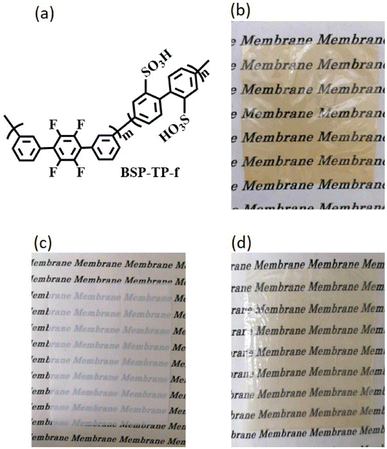 | ||
| Fig. 1 (a) Chemical structure of BSP-TP-f, and photos of (b) BSP-TP-f-4.1 membrane, (c) porous PE substrate, and (d) BSP-TP-f-4.1/PE reinforced membrane. | ||
The resulting BSP-TP-f ionomers were of high-molecular-weight (Mw = 242.4–533.0 kDa, Mn = 86.6–148.6 kDa) (Table 1) with good solubility in polar organic solvents such as N,N-dimethylacetamide and dimethyl sulfoxide but insoluble in water. From the 1H NMR spectra, the IEC was estimated to be 4.09 and 4.39 mequiv. g−1, respectively, nearly comparable to the target values. The ionomers provided brown, transparent, bendable membranes by solution casting (Fig. 1b), whose titrated IECs were 3.45 and 3.75 mequiv. g−1, indicating ca.16% of the sulfonic acid groups did not participate in the ion exchange reactions for both membranes probably because they were located in the hydrophobic domains. BSP-TP-f-4.1 and BSP-TP-f-4.5 ionomers were composited with the porous PE substrate (Fig. 1c) to obtain reinforced membranes (BSP-TP-f-4.1/PE and BSP-TP-f-4.5/PE) by a push coating method. Compared to the semi-transparent PE substrate, the reinforced membranes were more transparent without detectable defects such as pinholes and wrinkles (Fig. 1d). The titrated IECs of the BSP-TP-f-4.1/PE and BSP-TP-f-4.5/PE membranes were 1.97 and 2.31 mequiv. g−1 (Table 1), respectively, which were slightly higher than the calculated IEC values, 1.86 mequiv. g−1 for BSP-TP-f-4.1/PE and 2.19 mequiv. g−1 for BSP-TP-f-4.5/PE, taking the porosity and density of the PE substrate and assuming the full impregnation of the ionomers in the pores. The results suggest the existence of pure ionomer layer(s) with the composite layer, which is discussed below with the cross-sectional SEM images.
| Sample | IEC (mmol g−1) | Molecular weightd (kDa) | |||||||||||||||||||||||||||||||||||||||||||||||||||||||||||||||||||||||||||||||||||||||||||||||||
|---|---|---|---|---|---|---|---|---|---|---|---|---|---|---|---|---|---|---|---|---|---|---|---|---|---|---|---|---|---|---|---|---|---|---|---|---|---|---|---|---|---|---|---|---|---|---|---|---|---|---|---|---|---|---|---|---|---|---|---|---|---|---|---|---|---|---|---|---|---|---|---|---|---|---|---|---|---|---|---|---|---|---|---|---|---|---|---|---|---|---|---|---|---|---|---|---|---|---|---|
| Targeta | NMRb | Titratedc | Mw | Mn | Mw/Mn | ||||||||||||||||||||||||||||||||||||||||||||||||||||||||||||||||||||||||||||||||||||||||||||||
| a Calculated from the feed monomer ratio.b Calculated from the integrals of the relevant peaks in the 1H NMR spectra.c Determined by acid-base titration.d Determined by GPC. | |||||||||||||||||||||||||||||||||||||||||||||||||||||||||||||||||||||||||||||||||||||||||||||||||||
| BSP-TP-f-4.1 | 4.1 | 4.09 | 3.45 | 533.0 | 148.6 | 3.6 | |||||||||||||||||||||||||||||||||||||||||||||||||||||||||||||||||||||||||||||||||||||||||||||
| BSP-TP-f-4.5 | 4.5 | 4.39 | 3.75 | 242.4 | 86.6 | 2.8 | |||||||||||||||||||||||||||||||||||||||||||||||||||||||||||||||||||||||||||||||||||||||||||||
| BSP-TP-f-4.1/PE | — | — | 1.97 | — | — | — | |||||||||||||||||||||||||||||||||||||||||||||||||||||||||||||||||||||||||||||||||||||||||||||
| BSP-TP-f-4.5/PE | — | — | 2.31 | — | — | — | |||||||||||||||||||||||||||||||||||||||||||||||||||||||||||||||||||||||||||||||||||||||||||||
The cross-sectional SEM images of the reinforced membranes are shown in Fig. 2a and c, in which the sandwich-like structures (triple layers) were observed in both reinforced membranes. The top and bottom layers were composed of the parent, pure BSP-TP-f ionomer while the middle layer contained BSP-TP-f ionomer and PE substrate. The composite layers were homogeneous with pores fully impregnated with the ionomer throughout the view. The parent ionomer layers in the top and bottom were well-adhered to the middle composite layers, suggesting good interfacial compatibility between the BSP-TP-f ionomer and PE substrate. The thickness of each layer of the BSP-TP-f-4.1/PE membrane was ca. 4 μm (top), 7 μm (middle), and 3 μm (bottom), respectively, making up the total 14 μm-thickness. The thickness of the BSP-TP-f-4.5/PE reinforced membrane was similar (13.5 μm) with ca. 3 μm (top), 7 μm (middle), and 3.5 μm (bottom) thickness of each layer. The triple layer structure was responsible for the slightly higher titrated IEC of the reinforced membranes than the calculated values as mentioned above. The cross-sectional sulfur distribution in the EDS analyses revealed that the sulfur intensity was much smaller in the middle layer than in the top and bottom layers as expected (Fig. 2b and d). With normalizing the maximum sulfur density of the top or bottom layer as 100%, the average sulfur density of the middle layer was ca. 39% in BSP-TP-f-4.1/PE and ca. 41% in BSP-TP-f-4.5/PE, respectively, corresponding to the porosity of the PE substrate to further support the complete impregnation of the ionomers.
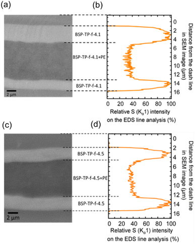 | ||
| Fig. 2 (a) and (c) Cross-sectional SEM images and (b and d) relative sulfur atom (Kα1) intensity in the EDS of the reinforced BSP-TP-f membranes. | ||
Properties of the reinforced membranes
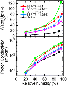
Fig. 3 compares humidity dependence of water uptake and proton conductivity of the parent and reinforced BSP-TP-f membranes, and Nafion at 80 °C. The parent BSP-TP-f-4.1 (23 μm thick, titrated IEC = 3.45 meq. g−1) and BSP-TP-f-4.5 (25 μm thick, titrated IEC = 3.75 meq. g−1) membranes showed much higher proton conductivity and water uptake than those of Nafion (25 μm, titrated IEC = 0.91 meq. g−1) due to their higher IEC values. In particular, the effect was more pronounced at high humidity. The highest conductivity was 560.8 mS cm−1 and 714.0 mS cm−1 at 95% RH for BSP-TP-f-4.1 and BSP-TP-f-4.5 membranes, respectively, compared to 187.2 mS cm−1 of Nafion at the same humidity. The reinforced BSP-TP-f-4.1/PE (14 μm thick, titrated IEC = 1.97 meq. g−1) and BSP-TP-f-4.5/PE (13.5 μm thick, titrated IEC = 2.31 meq. g−1) membranes exhibited smaller water uptake at minor expense of the proton conductivity, which was better understood by plotting proton conductivity as a function of water uptake at 80 °C (Fig. S1 and Table S1†). The water uptake of the reinforced BSP-TP-f-4.1/PE and BSP-TP-f-4.5/PE membranes at low humidity (20% RH) was 10.8% and 11.3%, which was 6.6% and 3.8% smaller than those of the parent BSP-TP-f-4.1 (17.4%) and BSP-TP-f-4.5 (15.1%) membranes, respectively. The conductivity of the reinforced BSP-TP-f-4.1/PE and BSP-TP-f-4.5/PE membranes at the same humidity (20% RH) was 6.9 mS cm−1 and 7.4 mS cm−1 compared with the parent BSP-TP-f-4.1 (10.7 mS cm−1) and BSP-TP-f-4.5 (8.5 mS cm−1) membranes. The similar effect was observed at higher humidity. The reinforced effect was also observed in the swelling ratio of the reinforced BSP-TP-f-4.1/PE (9% in-plane and 13% through-plane) and BSP-TP-f-4.5/PE (12% in-plane and 17% through-plane) membranes, compared with those of the parent BSP-TP-f-4.1 (27% in-plane and 25% through-plane) and BSP-TP-f-4.5 (40% in-plane and 51% through-plane) membranes (Table S2†).The reinforcement effect with the porous PE substrate for the BSP-TP-f ionomer membranes was also evaluated by stress/strain curves (Fig. 4 and Table S3†) and dynamic mechanical analyses (DMA) (Fig. S2†). The parent BSP-TP-f-4.1 and BSP-TP-f-4.5 membranes exhibited high Young's modulus (0.61 and 0.48 GPa) and yield stress (25.9 and 21.9 MPa) and maximum stress (39.6 and 28.5 MPa) but relatively low maximum strain (90% and 63%), typical for polyphenylene ionomer membranes. Compared with the parent membranes, the reinforced membranes BSP-TP-f-4.1/PE and BSP-TP-f-4.5/PE exhibited similarly high Young's modulus (0.36 and 0.27 GPa) and somewhat lower maximum stress but much larger maximum strain (453% and 284%), proving the significant reinforcement effect. In fact, the maximum strain of the reinforced membranes was comparable or even higher than that of Nafion membrane (335%).
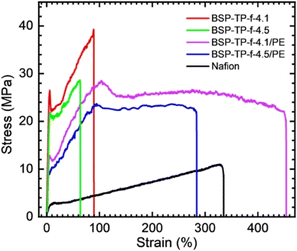 | ||
| Fig. 4 Stress–strain curves of parent and reinforced BSP-TP-f and Nafion membranes at 80 °C and 60% RH. | ||
The viscoelastic properties were measured at 80 °C as a function of the humidity (Fig. S2†). The storage moduli (E′) of parent and reinforced BSP-TP-f membranes was 0.7 × 10⁸–2.9 × 10⁹ Pa at dry condition and higher than that of Nafion (9.2 × 10⁷–1.5 × 10⁸ Pa). All membranes showed loss in E′ as increasing the humidity due to the softening effect of the absorbed water.21 There were no obvious peaks related with the glass transition in the loss moduli (E′) and tan![[thin space (1/6-em)]](https://www.rsc.org/images/entities/char_2009.gif) δ (=E′′/E′) curves.
δ (=E′′/E′) curves.
Fuel cell performance and accelerated durability
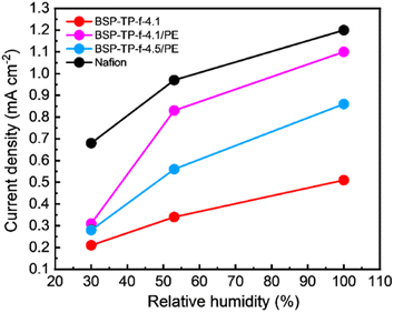
The parent BSP-TP-f-4.1 membrane (23 μm thick), reinforced BSP-TP-f-4.1/PE (14 μm thick) and BSP-TP-f-4.5/PE (13.5 μm thick) membranes and Nafion membrane (25 μm thick) were fabricated into membrane electrode assembly (MEA) with Nafion ionomer as the electrode binder and Pt/C as the catalyst in the catalyst layers for fuel cell evaluation (see ESI† for details). Unfortunately, the parent BSP-TP-f-4.5 membrane was not available due to mechanical failure caused by its high swelling (40% in-plane and 51% through-plane). Prior to the IV measurement, linear sweep voltammograms (LSVs) were measured (anode: H2, cathode: N2) to check the hydrogen permeability through the membrane (Fig. 5 and S3†). The hydrogen crossover current density was in the order of BSP-TP-f-4.1 < BSP-TP-f-4.5/PE < BSP-TP-f-4.1/PE < Nafion. As a typical perfluorosulfonic acid ionomer membrane, Nafion exhibited the highest current density despite its largest thickness among the tested membranes. The reinforced BSP-TP-f-4.1/PE and BSP-TP-f-4.5/PE membranes both provided higher current density than that of the parent BSP-TP-f-4.1 membrane. Taking the thickness into account, the hydrogen permeation current density at 100% RH was 11.37 mA cm−1, 14.3 mA cm−1, and 11.61 mA cm−1 for BSP-TP-f-4.1, BSP-TP-f-4.1/PE, and BSP-TP-f-4.5/PE, respectively. Hydrogen was probably permeable more through the hydrophobic PE substrate than the ionomers. The hydrogen permeation increased as increasing the humidity for all membranes because of the swelling. Although the humidity dependence of hydrogen permeation was more pronounced for the reinforced BSP-TP-f-4.1/PE and BSP-TP-f-4.5/PE membranes, the permeability was still smaller than that of Nafion membrane even at 100% RH.Fuel cells were evaluated with the parent BSP-TP-f-4.1 membrane, reinforced BSP-TP-f-4.1/PE and BSP-TP-f-4.5/PE, and Nafion membranes at 80 °C and 100% RH, 53% RH and 30% RH (Fig. 6). When feeding O2 as the oxidant, the open circuit voltages (OCVs) of the BSP-TP-f-4.1 (0.997 V), BSP-TP-f-4.1/PE (1.006 V) and BSP-TP-f-4.5/PE (0.999 V) cells at 100% RH were all higher than 0.99 V, supporting the aforementioned lower hydrogen permeability although they were only slightly lower than that of Nafion (1.024 V) at the same conditions. At 53% RH and 30% RH, the OCVs decreased to 0.993 V (53% RH) and 0.968 V (30% RH) for BSP-TP-f-4.1, 1.002 V (53% RH) and 0.962 V (30% RH) for BSP-TP-f-4.1/PE, 0.997 V (53% RH) and 0.991 V (30% RH) for BSP-TP-f-4.5/PE, and 1.021 V (53% RH) and 1.060 V (30% RH) for Nafion, respectively, because of the higher partial pressure of oxygen at lower humidity. The power density at 0.6 V were in the order of Nafion (0.944 W cm−2) > BSP-TP-f-4.1 (0.903 W cm−2) > BSP-TP-f-4.5/PE (0.837 W cm−2) > BSP-TP-f-4.1/PE (0.718 W cm−2) with feeding O2 as the oxidant at 100% RH (Table 2). The performance was in the same order at 53% RH and 30% RH. It is noted that the fuel cell performance of the reinforced BSP-TP-f-4.5/PE was nearly comparable to the parent BSP-TP-f-4.1 and Nafion at 100% RH and 53% RH. The minimum ohmic resistance at 100% RH was in the order of Nafion (0.073 Ω cm2) < BSP-TP-f-4.1 (0.065 Ω cm2) < BSP-TP-f-4.5/PE (0.086 Ω cm2) < BSP-TP-f-4.1/PE (0.101 Ω cm2), which were somewhat higher than those calculated from the membrane thickness and in-plane proton conductivity at 80 °C and 95% RH (0.013 Ω cm2 for Nafion, 0.004 Ω cm2 for BSP-TP-f-4.1, 0.003 Ω cm2 for BSP-TP-f-4.5/PE and 0.005 Ω cm2 for BSP-TP-f-4.1/PE) probably due to the contact resistance with the catalyst layers. The ohmic resistance became higher as decreasing the humidity as expected due to the lowered proton conductivity.
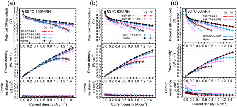 | ||
| Fig. 6 IR-included polarization curves, power densities and ohmic resistances for BSP-TP-f-4.1, BSP-TP-f-4.1/PE, BSP-TP-f-4.5/PE and Nafion fuel cells at 80 °C, (a) 100% RH, (b) 53% RH, (c) 30% RH. | ||
| Membrane | Minimum ohmic resistance (Ω cm2) | Power density at 0.6 V (W cm−2) | ||||
|---|---|---|---|---|---|---|
| 100% RH | 53% RH | 30% RH | 100% RH | 53% RH | 30% RH | |
| Nafion | 0.073 | 0.108 | 0.114 | 0.944 | 0.778 | 0.602 |
| BSP-TP-f-4.1 | 0.065 | 0.095 | 0.113 | 0.903 | 0.778 | 0.568 |
| BSP-TP-f-4.5/PE | 0.086 | 0.113 | 0.169 | 0.837 | 0.656 | 0.444 |
| BSP-TP-f-4.1/PE | 0.101 | 0.144 | 0.206 | 0.718 | 0.495 | 0.376 |
In the case of supplying air as the oxidant, the power density at 0.6 V of the pristine BSP-TP-f-4.1 cell decreased from 0.555 W cm−2 at 100% RH to 0.382 W cm−2 at 53% RH and 0.183 W cm−2 at 30% RH, which were comparable to those of the Nafion cell (100% RH: 0.560 W cm−2; 53% RH: 0.368 W cm−2; 30% RH: 0.223 W cm−2) (Table 3). The power density at 0.6 V of the reinforced BSP-TP-f-4.5/PE cell was 0.487 W cm−2 (100% RH), 0.300 W cm−2 (53% RH) and 0.123 W cm−2 (30% RH), only slightly lower than those of the pristine BSP-TP-f-4.1 cell. The fuel cell performance of the reinforced BSP-TP-f-4.1/PE cell was more dependent on the humidity than the other cells probably because the reinforced membrane tended to lose water with air supplied at high flow rate (>80 mL min−1 when the current density was larger than 0.5 A cm−2). The idea was supported by the larger ohmic resistance of the reinforced membrane cells with air than that with oxygen, in particular, at low humidity (30% RH).
| Membrane | Minimum ohmic resistance (Ω cm2) | Power density at 0.6 V (W cm−2) | ||||
|---|---|---|---|---|---|---|
| 100% RH | 53% RH | 30% RH | 100% RH | 53% RH | 30% RH | |
| Nafion | 0.069 | 0.119 | 0.214 | 0.560 | 0.368 | 0.223 |
| BSP-TP-f-4.1 | 0.059 | 0.115 | 0.165 | 0.555 | 0.382 | 0.183 |
| BSP-TP-f-4.5/PE | 0.082 | 0.149 | 0.409 | 0.487 | 0.300 | 0.123 |
| BSP-TP-f-4.1/PE | 0.099 | 0.198 | 0.687 | 0.497 | 0.227 | 0.073 |
The IR-free polarization curves are plotted in Fig. S4.† The performance of the reinforced BSP-TP-f-4.1/PE and BSP-TP-f-4.5/PE cells were comparable or only slightly lower than those of the parent BSP-TP-f-4.1 and Nafion cells, indicating good compatibility with the Nafion-binded catalyst layers. For more quantitative discussion, the mass activity of the Pt catalyst in the cathode at 0.85 V was calculated assuming negligibly small anodic overpotential and is summarized in Table S4.† The reinforced BSP-TP-f-4.1/PE (136.6 A gPt−1) and BSP-TP-f-4.5/PE (138.2 A gPt−1) membrane cells exhibited higher mass activity than that of the parent BSP-TP-f-4.1 (112.5 A gPt−1) membrane cell at 100% RH with O2 as the oxidant. The difference became even larger at lower humidity. With air as the oxidant, the mass activity was lower than that with O2, in particular, at low humidity. The reinforced BSP-TP-f-4.1/PE and BSP-TP-f-4.5/PE membrane cells still showed higher mass activity than that of the parent BSP-TP-f-4.1 membrane cell at any humidity investigated. The results suggest that the compatibility with the catalyst layers as well as small thickness of the reinforced BSP-TP-f-4.1/PE (14 μm thick) and BSP-TP-f-4.5/PE (13.5 μm thick) membranes contributed to higher utilization of the catalysts.
Fig. 7 shows durability of the cells using parent BSP-TP-f-4.1, reinforced BSP-TP-f-4.1/PE and BSP-TP-f-4.5/PE, and Nafion membranes in the accelerated durability test (wet/dry cycle test under OCV conditions), where the ohmic resistances at dry were ensured to be larger than 2.5 times than those at wet according to the US-DOE protocol.20 The initial OCV, accelerated durability, and average OCV decay are summarized in Table 4. The initial OCV at wet was 0.895 V for parent BSP-TP-f-4.1 cell, 0.912 V for reinforced BSP-TP-f-4.1/PE cell, 0.903 V for reinforced BSP-TP-f-4.5/PE cell and 0.905 V for Nafion cell, respectively, all slightly lower than those in the polarization curves (>0.97 V) due to the lower Pt loading (0.1 ± 0.02 mg cm−2 in the cathode and 0.2 ± 0.02 mg cm−2 in the anode) in the accelerated durability test. The OCV gradually decreased with the testing time until a sudden drop which was aroused by mechanical failure of the membranes. The accelerated durability (number of cycles at the time of the sudden drop of OCV) was in the order of BSP-TP-f-4.1/PE (40![[thin space (1/6-em)]](https://www.rsc.org/images/entities/char_2009.gif) 673 cycles) > BSP-TP-f-4.5/PE (22
673 cycles) > BSP-TP-f-4.5/PE (22![[thin space (1/6-em)]](https://www.rsc.org/images/entities/char_2009.gif) 235 cycles) > Nafion (8788 cycles) > BSP-TP-f (1640 cycles). The average decay of the OCV was 5.90 mV h−1 for BSP-TP-f-4.1 cell, 0.47 mV h−1 for BSP-TP-f-4.1/PE cell, 1.16 mV h−1 for BSP-TP-f-4.5/PE cell and 2.40 mV h−1 for Nafion cell, respectively. The durability of BSP-TP-f-4.1/PE and BSP-TP-f-4.5/PE membranes both exceeded the requirement in the US-DOE protocol (20
235 cycles) > Nafion (8788 cycles) > BSP-TP-f (1640 cycles). The average decay of the OCV was 5.90 mV h−1 for BSP-TP-f-4.1 cell, 0.47 mV h−1 for BSP-TP-f-4.1/PE cell, 1.16 mV h−1 for BSP-TP-f-4.5/PE cell and 2.40 mV h−1 for Nafion cell, respectively. The durability of BSP-TP-f-4.1/PE and BSP-TP-f-4.5/PE membranes both exceeded the requirement in the US-DOE protocol (20![[thin space (1/6-em)]](https://www.rsc.org/images/entities/char_2009.gif) 000 cycles). In particular, the durability of BSP-TP-f-4.1/PE membrane was more than 2 times larger than the US-DOE target. The superior durability of the reinforced BSP-TP-f-4.1/PE and BSP-TP-f-4.5/PE membranes than the parent BSP-TP-f-4.1 membrane was based on their improved mechanical properties acquired by the reinforcement.
000 cycles). In particular, the durability of BSP-TP-f-4.1/PE membrane was more than 2 times larger than the US-DOE target. The superior durability of the reinforced BSP-TP-f-4.1/PE and BSP-TP-f-4.5/PE membranes than the parent BSP-TP-f-4.1 membrane was based on their improved mechanical properties acquired by the reinforcement.
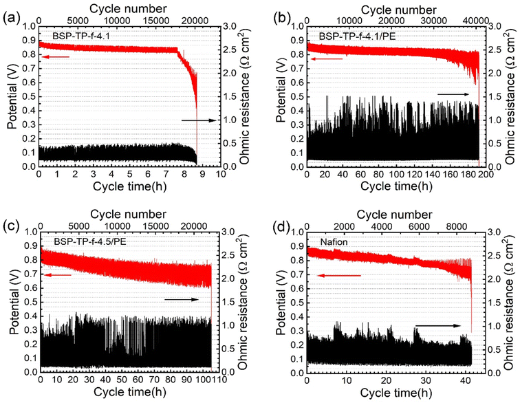 | ||
| Fig. 7 The accelerated durability test at 90 °C with H2 and air of (a) BSP-TP-f-4.1, (b) BSP-TP-f-4.1/PE, (c) BSP-TP-f-4.5/PE, and (d) Nafion cells. | ||
| Membrane | Initial OCVa (V) | Accelerated durability (cycles) | OCV decayb (mV h−1) | ||||||||||||||||||||||||||||||||||||||||||||||||||||||||||||||||||||||||||||||||||||||||||||||||
|---|---|---|---|---|---|---|---|---|---|---|---|---|---|---|---|---|---|---|---|---|---|---|---|---|---|---|---|---|---|---|---|---|---|---|---|---|---|---|---|---|---|---|---|---|---|---|---|---|---|---|---|---|---|---|---|---|---|---|---|---|---|---|---|---|---|---|---|---|---|---|---|---|---|---|---|---|---|---|---|---|---|---|---|---|---|---|---|---|---|---|---|---|---|---|---|---|---|---|---|
| a Initial OCV at wet condition (100% RH).b Calculated from (drop off OCV − initial OCV)/test time, where the drop off OCV and test time were determined at the cycle where the potential suddenly dropped. | |||||||||||||||||||||||||||||||||||||||||||||||||||||||||||||||||||||||||||||||||||||||||||||||||||
| BSP-TP-f-4.1 | 0.895 | 1640 | −5.90 | ||||||||||||||||||||||||||||||||||||||||||||||||||||||||||||||||||||||||||||||||||||||||||||||||
| BSP-TP-f-4.1/PE | 0.912 | 40![[thin space (1/6-em)]](https://www.rsc.org/images/entities/char_2009.gif) 673 673 |
−0.47 | ||||||||||||||||||||||||||||||||||||||||||||||||||||||||||||||||||||||||||||||||||||||||||||||||
| BSP-TP-f-4.5/PE | 0.903 | 22![[thin space (1/6-em)]](https://www.rsc.org/images/entities/char_2009.gif) 235 235 |
−1.16 | ||||||||||||||||||||||||||||||||||||||||||||||||||||||||||||||||||||||||||||||||||||||||||||||||
| Nafion | 0.905 | 8788 | −2.40 | ||||||||||||||||||||||||||||||||||||||||||||||||||||||||||||||||||||||||||||||||||||||||||||||||
After the test, the reinforced BSP-TP-f-4.1/PE and BSP-TP-f-4.5/PE membranes were recovered from the cells and the ionomers were extracted with DMSO and analyzed by NMR spectra and GPC (Fig. S5 and Table S5†). While the 19F NMR spectrum did not change, the 1H NMR spectra of the recovered ionomers showed minor changes. The peak integral indicated that the post-test BSP-TP-f-4.1 and BSP-TP-f-4.5 ionomers lost ca. 32% and ca. 27% of the sulfonic acid groups, respectively. The residual molecular weight was ca. 67% and 74% (based on Mw) for BSP-TP-f-4.1 and BSP-TP-f-4.5, respectively. The larger losses in IEC and molecular weight of the BSP-TP-f-4.1 were probably attributed to its longer durability cycles.
Conclusions
Mechanically and chemically robust, reinforced ionomer membranes were successfully prepared from fluorinated, tandemly sulfonated polyphenylene (BSP-TP-f) and porous polyethylene (PE) substrate via push coating method. The reinforced membranes contained dense and homogeneous triple layer structure with a total thickness smaller than 15 μm, where composite layers were sandwiched by pure BSP-TP-f thin layers. The reinforced membranes exhibited improved mechanical properties, in particular, the maximum strains became 5.0 (BSP-TP-f-4.1/PE) and 4.5 (BSP-TP-f-4.5/PE) times greater than those of the corresponding parent ionomer membranes. Despite incorporated with the non-conductive PE substrates, the reinforced membranes exhibited high proton conductivity of 303.2–389.2 mS cm−1 at 80 °C and high humidity (95% RH) attributable to the void-free impregnation of the ionomers into nanometer-sized pores of PE substrate with high porosity (44%). The maximum power density of fuel cells operated at 80 °C and 30% RH was of 0.444 W cm−2 and 0.376 W cm−2 for the reinforced BSP-TP-f-4.5/PE and BSP-TP-f-4.1/PE membranes and lower than that of the parent BSP-TP-f-4.1 membrane (0.568 W cm−2) due to the larger through-plane ohmic resistance. Although the reinforced membranes presented lower fuel cell performance than the parent membrane at low humidity, excellent durability was achieved in the accelerated durability test. The reinforced membranes survived for 40![[thin space (1/6-em)]](https://www.rsc.org/images/entities/char_2009.gif) 673 cycles (BSP-TP-f-4.1/PE) and 22
673 cycles (BSP-TP-f-4.1/PE) and 22![[thin space (1/6-em)]](https://www.rsc.org/images/entities/char_2009.gif) 235 cycles (BSP-TP-f-4.5/PE) in the accelerated durability test with wet/dry cycling under OCV conditions, much longer than that of the parent membrane and the US-DOE target. BSP-TP-f-4.1/PE and BSP-TP-f-4.5/PE membranes retained 67% and 74% in ionomer molecular weight (based on Mw) after the accelerated durability test, respectively. The excellent chemical stability and the improved mechanical durability of the reinforced membranes both contributed to the outstanding longevity in the accelerated durability test.
235 cycles (BSP-TP-f-4.5/PE) in the accelerated durability test with wet/dry cycling under OCV conditions, much longer than that of the parent membrane and the US-DOE target. BSP-TP-f-4.1/PE and BSP-TP-f-4.5/PE membranes retained 67% and 74% in ionomer molecular weight (based on Mw) after the accelerated durability test, respectively. The excellent chemical stability and the improved mechanical durability of the reinforced membranes both contributed to the outstanding longevity in the accelerated durability test.
Author contributions
Lin Guo: membrane preparation, investigation, and writing. Akihiro Masuda: structural analyses of membranes. Kenji Miyatake: conceptualization, supervision, writing, reviewing and editing, funding acquisition, and project administration.Conflicts of interest
There are no conflicts to declare.Acknowledgements
This work was partly supported by the New Energy and Industrial Technology Development Organization (NEDO), the Ministry of Education, Culture, Sports, Science and Technology (MEXT), Japan, through Grants-in-Aid for Scientific Research (18H05515) and MEXT Program: Data Creation and Utilization Type Material Research and Development Project (JPMXP1122712807), and JKA promotion funds from AUTORACE.References
- M. K. Singla, P. Nijhawan and A. S. Oberoi, Environ. Sci. Pollut. Res., 2021, 28, 15607–15626 CrossRef CAS PubMed.
- L. Fan, Z. Tu and S. H. Chan, Energy Rep., 2021, 7, 8421–8446 CrossRef.
- D. A. Cullen, K. C. Neyerlin, R. K. Ahluwalia, R. Mukundan, K. L. More, R. L. Borup, A. Z. Weber, D. J. Myers and A. Kusoglu, Nat. Energy, 2021, 6, 462–474 CrossRef CAS.
- K. Jiao, J. Xuan, Q. Du, Z. Bao, B. Xie, B. Wang, Y. Zhao, L. Fan, H. Wang, Z. Hou, S. Huo, N. P. Brandon, Y. Yin and M. D. Guiver, Nature, 2021, 595, 361–369 CrossRef CAS PubMed.
- P. C. Okonkwo, I. Ben Belgacem, W. Emori and P. C. Uzoma, Int. J. Hydrogen Energy, 2021, 46, 27956–27973 CrossRef CAS.
- L.-Y. Zhu, Y.-C. Li, J. Liu, J. He, L.-Y. Wang and J.-D. Lei, Pet. Sci., 2022, 19, 1371–1381 CrossRef CAS.
- M. Pan, C. Pan, C. Li and J. Zhao, Renewable Sustainable Energy Rev., 2021, 141, 110771 CrossRef CAS.
- J. Walkowiak-Kulikowska, J. Wolska and H. Koroniak, Phys. Sci. Rev., 2017, 2, 20170018 Search PubMed.
- F. Liu and K. Miyatake, J. Mater. Chem. A, 2022, 10, 7660–7667 RSC.
- R. S. Raja Rafidah, W. Rashmi, M. Khalid, W. Y. Wong and J. Priyanka, Polymers, 2020, 12, 1061 CrossRef PubMed.
- P. Khomein, W. Ketelaars, T. Lap and G. Liu, Renewable Sustainable Energy Rev., 2021, 137, 110471 CrossRef CAS.
- M. Adamski, T. J. G. Skalski, B. Britton, T. J. Peckham, L. Metzler and S. Holdcroft, Angew. Chem., Int. Ed. Engl., 2017, 56, 9058–9061 CrossRef CAS PubMed.
- J. Miyake, T. Mochizuki, R. Shimizu, R. Akiyama, M. Uchida and K. Miyatake, Sci. Adv., 2017, 3, eaao0476 CrossRef PubMed.
- H. Jang, T. Hong, J. Yoo, S. Lee, J. Pyo, S. C. Sutradhar, H. Ju and W. Kim, Int. J. Hydrogen Energy, 2015, 40, 14364–14370 CrossRef CAS.
- Electronic Components & Electrochemical Materials, https://www.gore.com/products/categories/electronic-components-electrochemical-materials, accessed February, 2023 Search PubMed.
- Perfluorosulfonic Acid (PFSA) Membranes for Fuel Cells, https://5.imimg.com/data5/FQ/TQ/MY-3121249/nafion-membrane-xl.pdf, accessed February, 2023 Search PubMed.
- J. Miyake, T. Watanabe, H. Shintani, Y. Sugawara, M. Uchida and K. Miyatake, ACS Mater. Au, 2021, 1, 81–88 CrossRef CAS PubMed.
- Z. Shang, M. M. Hossain, R. Wycisk and P. N. Pintauro, J. Power Sources, 2022, 535, 231375 CrossRef CAS.
- U.S. Department of Energy, Fuel Cell Technical Team Roadmap, https://www.energy.gov/sites/default/files/2017/11/f46/FCTT_Roadmap_Nov_2017_FINAL.pdf, accessed February, 2023 Search PubMed.
- L. Guo and K. Miyatake, ACS Appl. Energy Mater., 2022, 5, 5525–5530 CrossRef CAS.
- J. Ahn, R. Shimizu and K. Miyatake, J. Mater. Chem. A, 2018, 6, 24625–24632 RSC.
Footnote |
| † Electronic supplementary information (ESI) available. See DOI: https://doi.org/10.1039/d3ra01041d |
| This journal is © The Royal Society of Chemistry 2023 |

