 Open Access Article
Fabrication and characterization of glucose-oxidase–trehalase electrode based on nanomaterial-coated carbon paper†
Yanqing Zhang‡
a,
Varshini Selvarajan‡a,
Ke Shia and
Chang-Joon Kim *ab
*ab
aDepartment of Chemical Engineering and RIGET, Gyeongsang National University, Jinju, Republic of Korea. E-mail: cj_kim@gnu.ac.kr
bDepartment of Materials Engineering and Convergence Technology, Gyeongsang National University, 501, Jinju-daero, Jinju, Gyeongnam 52828, Republic of Korea
First published on 20th November 2023
Abstract
Multienzyme systems are essential for utilizing di-, oligo-, and polysaccharides as fuels in enzymatic fuel cells effectively. However, the transfer of electrons generated by one enzymatic reaction in a multienzyme cascade at the electrode may be impeded by other enzymes, potentially hindering the overall efficiency. In this study, carbon paper was first modified by incorporating single-walled carbon nanotubes (SWCNTs) and gold nanoparticles (AuNPs) sequentially. Subsequently, glucose oxidase (GOx) and a trehalase–gelatin mixture were immobilized separately on the nanostructured carbon paper via layer-by-layer adsorption to mitigate the electron transfer hindrance caused by trehalase. The anode was first fabricated by immobilizing GOx and trehalase on the modified carbon paper, and the cathode was then fabricated by immobilizing bilirubin oxidase on the nanostructured electrode. The SWCNTs and AuNPs were distributed adequately on the electrode surface, which improved the electrode performance, as demonstrated by electrochemical and morphological analyses. An enzymatic fuel cell was assembled and tested using trehalose as the fuel, and a maximum power density of 23 μW cm−2 was obtained at a discharge current density of 60 μA cm−2. The anode exhibited remarkable reusability and stability.
1. Introduction
Enzymatic fuel cells (EFCs) produce electricity by utilizing biomolecules, such as sugars and amino acids. They are attractive power sources for biological or medical applications, such as implantable and patchable electronic devices.1 Numerous attempts have been made thus far to fabricate single-enzyme electrodes for EFCs by utilizing monosaccharides, such as glucose, although there are other types of sugars. If di-, oligo-, and polysaccharides are used in such EFCs, the applicable range of sugars can be expanded, but there are no single enzymes that can oxidize these saccharides directly.2 Therefore, electrodes are often modified with several enzymes working parallelly or showing cascade functions to further extract the energy stored in these sugar substrates.2 Co-immobilization of multiple enzymes allows direct transfer of the reaction intermediates between the enzyme active sites to reduce diffusion limitations, thereby increasing the reaction rate.3,4 However, in multienzyme electrodes, electron transfer from the active site of one enzyme to the electrode may be inhibited by the other enzymes. We considered that this problem could be overcome using highly conductive nanomaterials as electrodes and immobilizing the enzymes on the electrode surfaces separately. In a previous study, we found that the current generation was improved by separately immobilizing glucose oxidase (GOx) and trehalase (TREH) on the surface of a gold electrode using agarose and by incorporating single-walled carbon nanotubes (SWCNTs) in the GOx layers to fabricate the anode.5SWCNTs have large surface areas, high electrical conductivity, chemical stability, and mechanical strength, and their use as electrode material provides additional electronic properties.6–8 Gold nanoparticles (AuNPs) are also an attractive material for fabricating enzyme electrodes owing to their high conductivity and high surface-to-volume ratio.9 Furthermore, the covalent attachment of AuNPs on SWCNTs10 or AuNP/SWCNT films11–13 can enhance the electrochemical performance of the GOx electrode. In addition to these nanomaterials, carbon paper (CP) has garnered attention for fabricating flexible electrodes for patchable biosensors, fuel cells, and redox flow batteries because of its high conductivity, chemical stability, and large surface area owing to the gathered structure of the fine carbon fibers.14
In this study, a bienzyme electrode was developed to generate a large amount of electricity using trehalose, a disaccharide, as fuel. Highly conductive electrodes were fabricated by modifying the surface of CP with SWCNTs and different loadings of AuNPs to compare their electrochemical performances. TREH and GOx were immobilized on the SWCNT-AuNP-modified CP by separating the two enzymes with gelatin. Gelatin is a biocompatible, flexible, and stable natural biopolymer that has been used as a matrix for enzyme immobilization.15–17 The performance of the GOx-TREH anode was evaluated by electrochemical and biochemical analyses. A cathode was also fabricated by immobilizing bilirubin oxidase (BOD) on the SWCNT-AuNP-modified CP. An EFC consisting of an anode and a cathode was constructed and evaluated by measuring the cell potential under a discharge current.
2. Experimental methods
2.1 Chemicals
Trehalose-degrading enzyme (TREH) from recombinant Escherichia coli (E-TREH, 4200 U mL−1, 303 U mg−1) was purchased from Megazyme (Wicklow, Ireland). Before use, the salts in the TREH solution were removed with a dialysis membrane having a molecular cutoff of 12–14 kDa (Spectra/Por®, Spectrum Labs, CA, USA), and the solution was concentrated with Amicon Ultra® centrifugation filters with 10 kDa molecular cutoff (Millipore, Ireland). GOX from Aspergillus niger (100![[thin space (1/6-em)]](https://www.rsc.org/images/entities/char_2009.gif) 000 units per g, product no. G2133), BOD from Myrothecium verrucaria, 5 nm AuNPs (product no. 741949), potassium dihydrogen phosphate (K2HPO4), sodium chloride (NaCl), potassium chloride (KCl), disodium hydrogen phosphate (Na2HPO4), citric acid monohydrate, 2,2′-azino-bis(3-ethylbenzothiazoline-6-sulfonic acid) diammonium salt (ABTS), ferrocene-methanol (FcMeOH), sodium citrate tribasic dihydrate, gelatin from porcine skin (powder, gel strength ∼300 g, Bloom), and other chemicals were purchased from Sigma-Aldrich (MO, USA). Nafion™ 117 (thickness: 183 μm) was purchased from Chemours (DE, USA), and carboxylic-acid-functionalized SWCNTs were purchased from Sigma-Aldrich (product no. 652490). According to the manufacturer's information and a previous report,18 the SWCNTs were produced by electric arc discharge with a carbonaceous content of 80–90% and metallic (nickel) impurities of 5–10%; they were then purified with nitric acid and left in a highly functionalized form with carboxylic acid. The average diameter of a single SWCNT is 1.4 ± 0.1 nm, and the bundle dimensions are 4–5 nm × 0.5–1.5 nm. All solutions were prepared in deionized (DI) water (1834 M cm) unless otherwise noted. The CP (HCP-020N) was purchased from WizMAC (Seoul, Korea), and polyvinyl chloride (PVC) film (thickness: 200 μm) was purchased from Office Depot (Seoul, Korea).
000 units per g, product no. G2133), BOD from Myrothecium verrucaria, 5 nm AuNPs (product no. 741949), potassium dihydrogen phosphate (K2HPO4), sodium chloride (NaCl), potassium chloride (KCl), disodium hydrogen phosphate (Na2HPO4), citric acid monohydrate, 2,2′-azino-bis(3-ethylbenzothiazoline-6-sulfonic acid) diammonium salt (ABTS), ferrocene-methanol (FcMeOH), sodium citrate tribasic dihydrate, gelatin from porcine skin (powder, gel strength ∼300 g, Bloom), and other chemicals were purchased from Sigma-Aldrich (MO, USA). Nafion™ 117 (thickness: 183 μm) was purchased from Chemours (DE, USA), and carboxylic-acid-functionalized SWCNTs were purchased from Sigma-Aldrich (product no. 652490). According to the manufacturer's information and a previous report,18 the SWCNTs were produced by electric arc discharge with a carbonaceous content of 80–90% and metallic (nickel) impurities of 5–10%; they were then purified with nitric acid and left in a highly functionalized form with carboxylic acid. The average diameter of a single SWCNT is 1.4 ± 0.1 nm, and the bundle dimensions are 4–5 nm × 0.5–1.5 nm. All solutions were prepared in deionized (DI) water (1834 M cm) unless otherwise noted. The CP (HCP-020N) was purchased from WizMAC (Seoul, Korea), and polyvinyl chloride (PVC) film (thickness: 200 μm) was purchased from Office Depot (Seoul, Korea).
2.2 Modification of CP with SWCNTs and AuNPs
The PVC film was attached to one side of a 3 M double-sided adhesive tape with a transparent film as the support matrix, and the CP (3 cm × 0.3 cm) was attached to the other side of the tape. The middle part of the CP was covered with the PVC film while the lower (0.5 cm × 0.3 cm) and upper parts were exposed for enzyme immobilization and connection to a potentiostat, respectively. The CP surface was modified with SWCNTs as follows: 6 mg of SWCNT powder was placed in a glass tube containing 6 mL of distilled water and sonicated in an ultrasonic bath (160HT, Sonicclean Pty Ltd., Seoul, Korea) for 3 h to obtain good dispersion. The supernatant was then separated from the slurry by centrifugation at 1106g and 25 °C for 10 min. The concentration of SWCNTs in the supernatant was 650 μg mL−1 when measured using a UV/vis spectrophotometer (UV-1601, Shimadzu, Japan) according to a previously reported method.19 About 30 μL of the supernatant was next placed on the exposed surface (0.15 cm2) of the CP and dried at room temperature for 2 h. This SWCNT-modified CP (CP-SWCNT) was further modified with AuNPs as necessary: 10–30 μL of the AuNP solution was placed on the surface of the CP-SWCNT and dried at room temperature (CP-SWCNT-AuNP) (Scheme 1).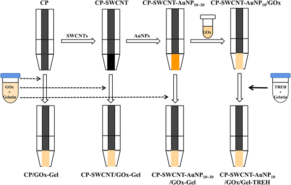 | ||
| Scheme 1 Modification of CP with SWCNTs or AuNPs and immobilization of GOx and TREH on the nanostructured electrodes. | ||
2.3 Fabrication of enzyme electrode
Various types of anodes were fabricated by immobilizing GOx or TREH on the modified CP by physical adsorption. The GOx solution was prepared by dissolving lyophilized GOx in 0.1 M phosphate-buffered saline (PBS, pH 7.0).5 Solutions of GOx (20 mg mL−1) and gelatin (20 mg mL−1) were mixed in a 1![[thin space (1/6-em)]](https://www.rsc.org/images/entities/char_2009.gif) :
:![[thin space (1/6-em)]](https://www.rsc.org/images/entities/char_2009.gif) 1 ratio, and about 10 μL of the mixture was dropped on the surface of the CP, CP-SWCNT, and CP-SWCNT-AuNP10–30 before drying at room temperature for 2 h; these electrodes correspond to CP/GOx-Gel, CP-SWCNT/GOx-Gel, and CP-SWCNT-AuNP10–30/GOx-Gel, respectively. The bienzyme electrode (CP-SWCNT-AuNP10/GOx/Gel-TREH) was fabricated by immobilizing GOx and TREH on CP-SWCNT-AuNP10 through layer-by-layer adsorption. About 10 μL of the GOx solution (10 mg mL−1) was first placed on the surface of the CP-SWCNT-AuNP10; then, 10 μL of the TREH–gelatin mixture (210 U mL−1 TREH and 10 mg mL−1 gelatin) was placed on the surface of GOx (Scheme 1). The BOD-based cathode was then fabricated by sequential immobilization of BOD (1.25 U) and gelatin (0.1 mg).
1 ratio, and about 10 μL of the mixture was dropped on the surface of the CP, CP-SWCNT, and CP-SWCNT-AuNP10–30 before drying at room temperature for 2 h; these electrodes correspond to CP/GOx-Gel, CP-SWCNT/GOx-Gel, and CP-SWCNT-AuNP10–30/GOx-Gel, respectively. The bienzyme electrode (CP-SWCNT-AuNP10/GOx/Gel-TREH) was fabricated by immobilizing GOx and TREH on CP-SWCNT-AuNP10 through layer-by-layer adsorption. About 10 μL of the GOx solution (10 mg mL−1) was first placed on the surface of the CP-SWCNT-AuNP10; then, 10 μL of the TREH–gelatin mixture (210 U mL−1 TREH and 10 mg mL−1 gelatin) was placed on the surface of GOx (Scheme 1). The BOD-based cathode was then fabricated by sequential immobilization of BOD (1.25 U) and gelatin (0.1 mg).
2.4 Surface characterizations and biochemical analyses of the electrodes
Transmission electron microscopy (TEM) images were obtained using a TF30ST (FEI, Hillsboro, USA) at an operating voltage of 300 kV to observe the SWCNTs in the dispersion or supernatant. The surface morphology of the modified CP was observed by field-emission scanning electron microscopy (FE-SEM, Apero 2S, Thermo Fisher Scientific) coupled with energy-dispersive X-ray spectroscopy (EDS, Oxford Instrument, Aztec Software) at an accelerating voltage of 20 kV. Prior to analysis, all samples were mounted on carbon tape and coated with Pt using a Cressington sputter coater 208HR to a thickness of about 0.1–10 nm under a vacuum pressure of 0.1 mbar.The activity of the immobilized GOx was measured using a coupled enzyme assay. The assay solution containing o-dianisidine, glucose, and horseradish peroxidase was saturated with oxygen by bubbling air for 30 min, and a 3 mL aliquot was used to treat a solution of free GOx (0.1 mL, 0.1 mg mL−1) or the GOx-immobilized electrode in a spectrophotometer cuvette. The increase in absorbance at 460 nm was measured at 1 min intervals using a UV/vis spectrophotometer. The specific activity of GOx was calculated from the initial linear portion of the obtained curve for a known GOx content. One unit of GOx activity is defined as the amount of enzyme that catalyzes the oxidation of 1 μmol of glucose per minute at room temperature and pH 6.0. The equation for calculating GOx activity is noted in a previous work.5
2.5 Electrochemical analyses of the enzyme electrodes and EFC performance
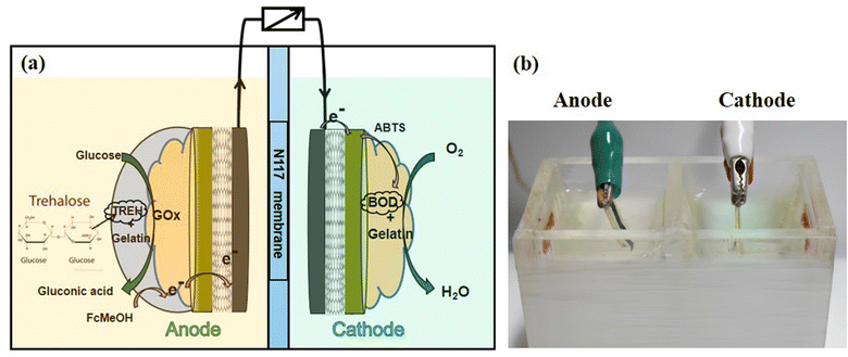
The electrochemical cell was a three-electrode system with a working electrode, a counter electrode (Pt), and an Ag/AgCl reference electrode (LF-2, Innovative Instruments Inc., Tampa, FL, USA). Cyclic voltammetry (CV) was performed at a scan rate of 25 mV s−1 in 8 mL of 10 mM PBS (pH 6.0) containing 0.1 mM FcMeOH for evaluation of the modified CP. The electrode was incubated in electrolyte for 15 min prior to applying a constant oxidation potential of around 0.3 V (vs. Ag/AgCl) to the electrochemical system for chronoamperometry (CA). The electrolyte was supplemented with glucose (30 mM) and trehalose (30 mM) for CV analyses of the GOx- and GOx-TREH-immobilized electrodes, respectively, whereas the electrochemical properties of the BOD electrode were measured using 100 mM citrate buffer (pH 5.0) containing 1 mM ABTS under saturated O2 conditions.The EFC was assembled with a CP-SWCNT-AuNP10/GOx/Gel-TREH anode and CP-SWCNT-AuNP10/BOD/Gel cathode, as shown in Fig. 1. The chambers of the EFC were separated by an N117 membrane. The anodic chamber was filled with 10 mM PBS (pH 6.0) containing trehalose (30 mM) and FcMeOH (0.1 mM), whereas the cathodic chamber was filled with 100 mM citrate buffer (pH 5.0) supplemented with 1 mM ABTS. Electrochemical measurements were performed at room temperature using an electrochemical workstation (CH Instruments, model 660D, Houston, TX, USA). The discharge curves of the EFC were recorded at variable discharge currents. The current and power densities were calculated based on the geometric area (0.15 cm2) of the bare CP.
3. Results and discussion
3.1 Characterization of SWCNT-AuNP-modified CP electrodes
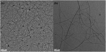
As shown in the TEM image, entangled SWCNT bundles were observed in the SWCNT dispersion while most of the SWCNTs in the supernatant were not bundled (Fig. 2). Owing to their aromatic structure, the CNTs tend to bundle via strong cohesive van der Waals interactions and are insoluble in water.20 Carboxylated SWCNTs were used because the hydrophilic carboxylic group allows dispersion of the SWCNTs.20 In addition, a sonication step was adopted to improve the dispersion of the SWCNTs in an aqueous medium. It has been reported that sonication induces high shear forces by acoustic cavitation, which causes clefts in the SWCNT bundles; the SWCNT surfaces in these clefts are then exposed to the aqueous solution.21,22 The results clearly show that carboxylated SWCNTs are dispersed well in the aqueous solution by sonication; further, the nanotube bundles and aggregates can be successfully removed by centrifugation.The supernatant containing well-dispersed SWCNTs was used to modify the surface of the CP. The SEM images show the surface morphologies of the bare, SWCNT-, and SWCNT-AuNP-modified CPs (Fig. S1†). The network of SWCNTs is clearly observed on the surface of the SWCNT-modified CP, whereas smooth stacked sheets are seen on the bare CP. This demonstrates that the SWCNTs are evenly and adequately adsorbed on the surface of the CP. The AuNPs decorating the SWCNTs were also dispersed along the nanotubes and exhibited spherical forms on the SWCNT-AuNP-modified CP. The SWCNTs can be clearly observed under the AuNP layer and are compactly attached to the walls of the nanotubes, suggesting the formation of an SWCNT-AuNP nanocomposite on the CP. The cross-sectional morphologies of the CP before and after modification with SWCNTs and AuNPs were further characterized as shown in Fig. 3. Chemical information on the electrodes was also revealed via EDS analysis. The CP was characterized as interconnected carbon fibers and carbon flakes that are randomly scattered over the surface and interior. It is noted that the SWCNTs are seamlessly integrated into the carbon fiber network comprising the CP, effectively bridging any gaps and enveloping the entire surface. The atomic percentage of oxygen over a circular area of the corresponding CP-SWCNT electrode increased to 9.44% after modification from 4.06% of the bare CP. Correspondingly, the O/C ratio of the CP-SWCNT increased to 0.1 from 0.04 of the CP. There are oxygen-containing groups, such as carbonyl (–CO–) and ether (–C–O–C–), in the carboxylated SWCNTs;23 therefore, the increase in O/C ratio indicates the incorporation of SWCNTs on the surface of the CP. The EDS spectra confirm the presence of AuNPs on the surface of CP-SWCNT-AuNP10, and the atomic percentage of gold (Au) acquired from representative areas of the CP-SWCNT-AuNP10 was 0.24%. However, there was no substantial variation in the Au content among CP-SWCNT-AuNP10, CP-SWCNT-AuNP20, and CP-SWCNT-AuNP30 (data not presented), which is likely attributable to the uneven distribution of AuNPs on the CP-SWCNT or limitations of quantitative analysis when using SEM-EDS. Nevertheless, it was confirmed using SEM and EDS that both SWCNTs and AuNPs were successfully adsorbed on the surface of the CP.
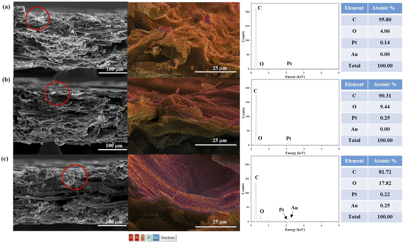 | ||
| Fig. 3 SEM images and EDS mappings of the cross sections of (a) CP, (b) CP-SWCNT, and (c) CP-SWCNT-AuNP10. | ||
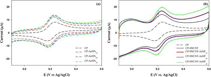
The electrochemical properties of the bare and modified CPs were investigated by CV. As shown in Fig. 4 and Table 1, the cyclic voltammograms of the bare and modified CPs exhibited a pair of redox waves in the tested potential ranges, and the formal potential of these peaks was taken as the average of Epa and Epc, about 0.2 V, which is near the standard potential of FcMeOH.24 For all electrodes, the responses were similar to that of the reversible one-electron transfer with a peak-to-peak separation of ΔEp = |Eoxp − Eredp| = 40–60 mV, which is close to the theoretical value of 59 mV for the one-electron process.25 Notably, the ΔEp of the modified CP is less than that of the bare CP, indicating better electron transfer kinetics for the modified CP.26 The current generation with the modified CP was significantly higher than that of the bare CP upon covering the CP surface with 10 μL of AuNPs (CP-AuNP10) (Fig. 4(a)). A subtle rise in the current peak was observed as the dosage of AuNPs was augmented to 20 μL. However, there was no further increase in current as the dosage of AuNPs was increased to 30 μL (CP-AuNP30). Upon modifying CP with SWCNTs, a notable increase in current was observed. This increase was further amplified when the CP-SWCNTs were subjected to modification with 10 μL of AuNPs (CP-SWCNT-AuNP10). Moreover, this incremental trend was further noted to be present, albeit slight, upon increasing the AuNPs dosage to 30 μL (CP-SWCNT-AuNP30), as demonstrated in Fig. 4(b) and Table 1. This shows how much conductivity can be increased with relatively few AuNPs on CP and CP-SWCNT, but there is a limit to improving the conductivity of the electrode only by increasing the loading of AuNPs.
| Electrode | Epa (mV) | Epc (mV) | ΔEp (mV) | Ipa (μA) | Ipc (μA) | Ipa/Ipc |
|---|---|---|---|---|---|---|
| CP | 240 ± 3 | 180 ± 3 | 60 ± 1 | 8.2 ± 0.4 | −6.2 ± 0.4 | 1.3 |
| CP-AuNP10 | 230 ± 2 | 180 ± 2 | 50 ± 4 | 12.9 ± 2.0 | −9.9 ± 2.1 | 1.3 |
| CP-AuNP20 | 230 ± 3 | 190 ± 1 | 40 ± 4 | 13.7 ± 0.1 | −11.0 ± 0.2 | 1.2 |
| CP-AuNP30 | 230 ± 2 | 190 ± 2 | 40 ± 0 | 13.1 ± 1.2 | −10.9 ± 0.9 | 1.2 |
| CP-SWCNT | 230 ± 2 | 180 ± 2 | 50 ± 4 | 14.1 ± 0.7 | −11.8 ± 0.2 | 1.2 |
| CP-SWCNT-AuNP10 | 230 ± 2 | 180 ± 4 | 50 ± 5 | 16.9 ± 1.1 | −14.1 ± 1.1 | 1.2 |
| CP-SWCNT-AuNP20 | 230 ± 2 | 190 ± 3 | 40 ± 4 | 13.7 ± 0.5 | −11.0 ± 0.6 | 1.2 |
| CP-SWCNT-AuNP30 | 230 ± 7 | 180 ± 4 | 50 ± 5 | 19.8 ± 1.0 | −17.0 ± 0.7 | 1.2 |
An earlier study demonstrated a substantial conductivity increase with a relatively low gold nanoparticle content but, this effectiveness diminishes when significant agglomeration occurs at high concentrations due to the formation of large electron tunneling gaps between individual nanoparticles during substantial nanoparticle agglomeration, reducing the effective conductive paths for electron transfer.27,28 On the contrary, by integrating SWCNTs and AuNPs, it was found that electrode performance was further improved through the increased loading of AuNPs in this study. Consequently, the CP-SWCNT-AuNP electrode exhibited the highest peak current, achieving a 2.1–2.4-fold increase in current compared to the bare CP by increasing the loading of AuNPs up to 30 μL on CP-SWCNT. This enhancement can be attributed to the large surface-to-volume ratio of the SWCNTs and AuNPs combined with the highly porous structure of the networks of interconnected SWCNTs, which creates a larger interface for electron transfer compared to the CP or CP-AuNP. The results indicated that the electrochemical performance of the electrode was enhanced by the adsorption of SWCNTs and AuNPs on the CP surface, which may be attributable to the increased electrochemical surface area and the enhanced electron transfer ability of the electrode as reported previously.29,30
3.2 Electrochemical characterizations of GOx-immobilized electrodes
Three kinds of GOx electrodes were fabricated by immobilizing GOx on bare CP, CP-SWCNT, and CP-SWCNT-AuNP10. In the absence of glucose, small quasi-reversible oxidation and reduction peaks of FcMeOH were observed at around 0.2 V (vs. Ag/AgCl) for all electrodes (Fig. S2†). Notably, the anodic peak potential of the voltammogram shifted to a slightly more positive value and anodic peak currents increased sharply in the presence of glucose (30 mM) for all electrodes compared to the CVs in the absence of glucose (Fig. 5(a)). The potential shift and S-shaped curves are believed to be caused by the rapid oxidation of glucose by the catalytic enzyme reaction.31 The oxidation current intensity increased in the following order: CP/GOx-Gel < CP-SWCNT/GOx-Gel < CP-SWCNT-AuNP10/GOx-Gel. This indicates that the SWCNTs and AuNPs contribute synergistically to enhance the electrical performance of the GOx electrode.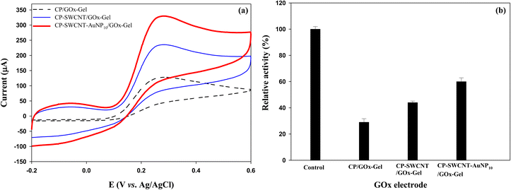 | ||
| Fig. 5 (a) Cyclic voltammograms and (b) relative activities of CP/GOx-Gel, CP-SWCNT/GOx-Gel, and CP-SWCNT-AuNP10/GOx-Gel. | ||
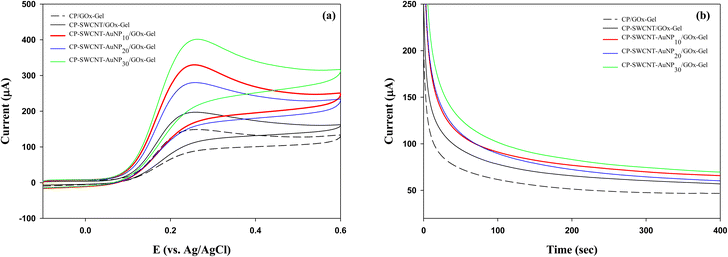
The effect of AuNP loading was further investigated for GOx immobilized on CP-SWCNT-AuNP in an electrolyte supplemented with 30 mM glucose using CV and CA. The cyclic voltammogram (a) and current responses vs. time (b) are shown in Fig. 6. Similar trends were observed for both the CV and CA; a higher current was generated when GOx was immobilized on CP-SWCNT than CP. Attachment of GOx on CP-SWCNT-AuNP resulted in a higher current than on CP-SWCNT. Furthermore, the current increased slightly when the AuNP loading increased from 10 μL to 30 μL, while no significant difference was observed between CP-SWCNT-AuNP10/GOx-Gel and CP-SWCNT-AuNP20/GOx-Gel. It was considered that the presence or absence of a nanomaterial (SWCNTs or AuNPs) influenced the GOx electrode performance critically, whereas the effect of AuNP loading was not critical considering the cost of the AuNPs. Therefore, in all subsequent experiments, CP-SWCNT-AuNP10 was used as the bare electrode.
The activity of the immobilized GOx was measured, and varying activities were observed from the GOx attached to CPs with and without modification (Fig. 5(b)). The highest and lowest activities were observed for CP-SWCNT-AuNP10/GOx-Gel and CP/GOx-Gel, respectively. These biochemical data are consistent with the corresponding electrochemical data. Enhancement of enzyme activity in the presence of AuNPs was demonstrated for various enzymes, including GOx, in previous studies.32,33 It is known that AuNPs may allow proteins to retain their biological activities upon adsorption; therefore, electrode modification with this material provides a microenvironment similar to that of the redox proteins in native systems.34 It has been suggested that the distance between the FAD center and electrode surface is reduced by the partial unfolding of GOx as it is adsorbed on the nanotubes.32 It was previously demonstrated that the electrochemical performance of the GOx electrode could be enhanced by the synergistic interactions of AuNPs and SWCNTs.33,35 Together with these previous demonstrations, we suggest that the SWCNTs and AuNPs cooperate to enhance the performance of the GOx electrode by not only increasing the activity of GOx but also providing extra electron transfer pathways.
3.3. Electrochemical characterizations of GOx-TREH electrodes
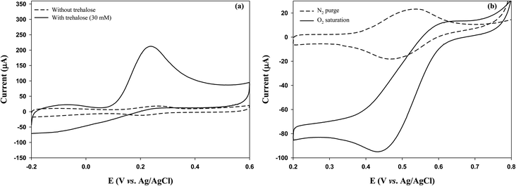
Initially, we investigated whether the GOx electrode could generate electrical current by utilizing trehalose-degradation products. Trehalose solution (30 mM) was treated with TREH (2.1 U) for 3 h, and the GOx electrode (CP-SWCNT-AuNP10/GOx-Gel) was immersed in the TREH-digested solution before performing CV analysis in the presence of FcMeOH (1 mM). The peak current intensity was strong in the presence of the TREH-digested product, whereas a weak current peak was observed in the trehalose solution without breakdown (Fig. S3†). In our previous study, we observed that glucose is readily released during incubation of trehalose solution in the presence of TREH;5 this result clearly indicates that TREH successfully degrades trehalose into glucose to produce electrical energy by the GOx electrode.Next, a bienzyme electrode consisting of GOx and TREH was fabricated. As mentioned above, GOx and TREH were immobilized separately on the electrode surface by attaching the TREH–gelatin mixture to the surface of CP-SWCNT-AuNP10/GOx. Fig. 7(a) shows the electrochemical behaviors of the GOx-TREH electrode (CP-SWCNT-AuNP10/GOx/Gel-TREH) with and without trehalose in the electrolyte. A high anodic peak current of 216 μA was observed at 0.24 V in the presence of trehalose, whereas a small reversible current was noted in the absence of trehalose; this clearly indicates that immobilized TREH can degrade trehalose efficiently with minimal electron transfer resistance from GOx to the electrode. Table 2 summarizes the results of some previous and current research findings. The calculated current density in this study based on the surface area of the bare CP was 1.4 mA cm−2, which is 24 times higher than that reported by Rasmussen.36 To the best of our knowledge, this is one of the highest values obtained for a GOx-TREH electrode using trehalose as the fuel to generate current. This is because the CP provides a large surface area for immobilizing the SWCNTs-AuNPs, which serve as good electron conductors and anchoring points for enzyme immobilization. Additionally, separate immobilizations of GOx and TREH impart dual enzymatic functions to the electrode while minimizing the electron transfer resistance.
| Anode | Cathode | OCV (V) | Max. oxidation current density (mA cm−2) | Power density (μW cm−2) | Ref. |
|---|---|---|---|---|---|
| a CR, carbon rod; PFCE, plastic-formed carbon electrode; CHL, cockroach hemolymph; CC, carbon cloth; CP, carbon paper. | |||||
| CR/PEGDGE-Os-modified polymer-GOx-TREH in insect | CR/PEGDGE-Os-modified polymer-BOD | — | 0.065 at 0.25 V | 55 | 36 |
| PFCE/ferrocene/GOx in CHL with added TREH and mutarotase | PFCE/BOD + air-diffusion | 0.3 | 0.006 | 10.5 | 40 |
| CC/VK3/NADH/GDH in insect with added TREH and mutarotase | CC/ABTS/BOD + air-breathing | 0.75 | 1.18 at 0.6 V | 285 | 41 |
| CP-SWCNT-AuNP10/GOx/Gel-TREH in PBS (pH 6.0) with added trehalose (30 mM) and FcMeOH (0.1 mM) | CP-SWCNT-AuNP10/BOD/Gel in oxygen-saturated 100 mM citrate buffer (pH 5.0) with added ABTS (1 mM) | 0.65 | 1.4 at 0.24 V | 23 | This study |
However, the anodic peak current of CP-SWCNT-AuNP10/GOx/Gel-TREH in the trehalose solution was 1.5 times lower than that obtained with CP-SWCNT-AuNP10/GOx-Gel in the glucose solution. Although these distinctions are intriguing, comparable instances can be observed in other earlier publications; in the three-enzyme cascade oxidation of sucrose using invertase, GOx, and fructose dehydrogenase, it was reported that the cascade reaction was limited by the slow autorotation of the glucose produced from sucrose before being utilized by GOx.37,38 The reaction was accelerated by adding mutarotase to easily transform α-D-glucose to β-D-glucose, which is the proper form of GOx.39 Therefore, we considered that current generation by the GOx-TREH electrode in the trehalose solution could be enhanced by adding mutarotase to the electrode. Furthermore, optimizing the loading of TREH could improve the current generation, as demonstrated in a previous study.5
3.4 Evaluation of CP-SWCNT-AuNP10/GOx/Gel-TREH as an anode for a high-power EFC
Because the EFC needs both an anode and a cathode, the cathode was fabricated by immobilizing BOD on CP-SWCNT-AuNP10 and sequentially covering the surface with gelatin to prevent enzyme leakage. The cathodic performance of the BOD electrode (CP-SWCNT-AuNP10/BOD/Gel) was evaluated in citrate buffer (pH 5.0) supplemented with 1 mM ABTS. It is worth noting that the reduction peak increased significantly in the oxygen-saturated electrolyte, whereas a small reversible current peak was observed in the electrolyte purged with nitrogen (Fig. 7(b)). This result clearly indicates that the immobilized BOD effectively catalyzes the reduction of oxygen to water in cooperation with electrons transferred from the electrode via ABTS.Herein, the EFC was assembled such that the anode (CP-SWCNT-AuNP10/GOx/Gel-TREH) and cathode (CP-SWCNT-AuNP10/BOD/Gel) were separated by a Nafion 117 membrane, as mentioned previously. The EFC shows an open-circuit voltage (OCV) of approximately 0.65 V, but the cell voltage dropped when the current was drawn from the cell. Fig. 8(a) shows the I–V curve of the EFC for different discharge current densities, each of which was calculated by dividing the corresponding discharge current by the area of the bare CP. The cell voltage decreased gradually and then dropped rapidly when the discharge current increased above 60 μA cm−2. The power density (P = J × V) increased with the increase in discharge current density; when the discharge current density was 60 μA cm−2, the cell voltage decreased to 0.38 V, at which point the maximum power density of 23 μW cm−2 was obtained. The cell voltage was maintained in the range of 0.26–0.31 V for more than 40 min during discharge at 60 μA cm−2 (Fig. 8(b)), indicating stable operation of the EFC. The maximum power density observed in this study was twice that obtained by Shoji et al.40 and 1.6 times that obtained by Rasmussen36 in PBS supplemented with trehalose (50 mM). To the best of our knowledge, the EFCs developed in this study produce some of the highest power among trehalose EFCs known thus far. However, the performance of the EFC did not appear to increase as much as that of the anode. Accordingly, we considered that the EFC performance could be further improved by combining a high-performance cathode.
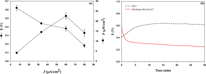 | ||
| Fig. 8 (a) Cell voltage and cell power density curves under different discharge currents; (b) time profiles of the cell voltages under discharge. | ||
3.5 Reusability of CP-SWCNT-AuNP10/GOx/Gel-TREH
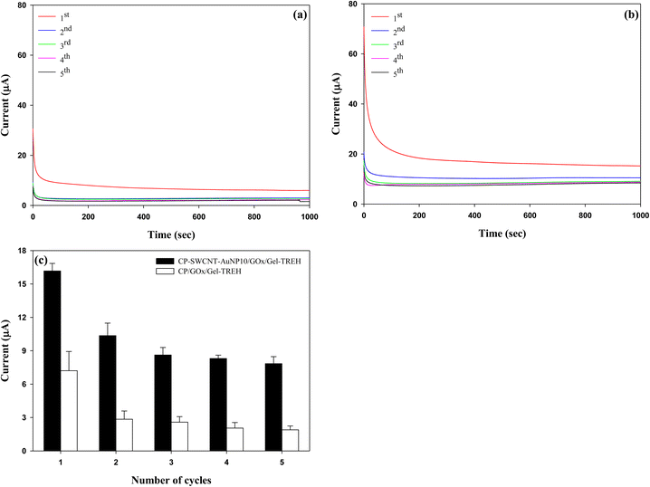
The reusability of a used CP-SWCNT-AuNP10/GOx/Gel-TREH was investigated by replacing the trehalose solution (30 mM) with a freshly prepared solution after each cycle in the chronoamperometric measurements while maintaining a fixed potential of 0.3 V. A parallel analysis was performed with the CP/GOx/Gel-TREH as the control. The current responses of both electrodes achieved steady states within 300 s and remained unchanged throughout the testing time of each cycle, as depicted in Fig. 9(a) and (b). The average currents generated between 300 and 700 s were calculated and compared subsequently, as illustrated in Fig. 9(c). The current responses exhibited similarities across repeated cycles for both electrodes. Although there was a decrease in the current response over the initial three cycles, there was no further decline in the current generation subsequently. Nonetheless, discrepancies were noted in both the degree of current generation and rate of current reduction between the two electrodes: during the initial use, CP-SWCNT-AuNP10/GOx/Gel-TREH yielded a current response of 16.2 μA while CP/GOx/Gel-TREH produced 7.2 μA. With subsequent usage, the current responses of CP-SWCNT-AuNP10/GOx/Gel-TREH and CP/GOx/Gel-TREH decreased to 64% and 39% of their initial cycle values, respectively; during the third usage, the current responses further dropped to 53% and 36% for the corresponding electrode configurations.The decline in current responses observed during the first two cycles may be attributed to detachment of the loosely bound enzymes, because the electrodes can be reused without significant loss of current generation from the third cycle onward. Emphasizing this consistent trend, comparable results have also been documented for lipase immobilized on gelatin blends with alginate.42 As mentioned above, the results clearly demonstrate that bienzyme electrodes integrated with nanomaterials can be used repeatedly while maintaining high enzyme activities through synergistic interplay between the nanomaterials and enzymes. Similar findings have been documented for the beneficial effects of AuNPs after repeated cycles, leading to the conclusion that AuNPs enhance the performance and reusability of an electrode when combined with the GOx.43
4. Conclusion
This study shows that the selection of electrode materials with high conductivities and efficient immobilization of enzymes on the electrode are critical for fabricating high-performance multienzyme electrodes. The enzyme activity and current generation are maximal when GOx is immobilized on CP-SWCNT-AuNP rather than CP or CP-SWCNT, indicating the synergistic contributions of SWCNTs and AuNPs to enhancing the electrical performance of the GOx electrode. Separate immobilizations of GOx and TREH using gelatin impart dual enzymatic functions to the electrode while minimizing the electron transfer resistance. An EFC consisting of a CP-SWCNT-AuNP10/GOx/Gel-TREH anode and CP-SWCNTs-AuNP10/BOD/Gel cathode is shown to stably generate high power. The optimized electrode can be used repeatedly while maintaining high activity. Thus, the structure proposed in this study is expected to contribute towards the fabrication of various multienzyme electrodes for sensors or fuel cells.Author contributions
YZ: methodology, formal analysis, writing – original draft. VS: additional experiments, analysis, writing – revised manuscript. KS: formal analysis. CK: supervision, conceptualization, writing – review & editing.Conflicts of interest
There are no conflicts of interest to declare.Acknowledgements
This work was supported by the National Research Foundation of Korea (NRF) grant funded by the Korea government (MSIT) (NRF-2017R1D1A1B03029032, NRF-2020R1F1A1054433, and 2021RIS-003).References
- X. Xiao, H. Xia, R. Wu, L. Bai, L. Yan, E. Magner, S. Cosnier, E. Lojou, Z. Zhu and A. Liu, Chem. Rev., 2020, 3, 225–244 Search PubMed.
- M. Kizling, M. Dzwonek, A. Nowak, L. Tymecki, K. Stolarczyk, A. Wieckowska and R. Bilewicz, Nanomaterials, 2020, 10, 1534 CrossRef CAS PubMed.
- F. Visser, B. Muller, J. Rose, D. Prufer and G. A. Noll, Sci. Rep., 2016, 6, 30839 CrossRef CAS PubMed.
- E. T. Hwang and S. Lee, ACS Catal., 2019, 9, 4402–4425 CrossRef CAS.
- X. Wang, Y. Q. Zhang, H. Kim and C.-J. Kim, Electrochim. Acta, 2021, 392, 138974 CrossRef CAS.
- M. Sireesha, V. J. Babu, A. S. K. Kiran and S. Ramakrishna, Nanocomposites, 2018, 4, 36–57 CrossRef CAS.
- Y. Liu, J. Zhang, Y. Cheng and S. P. Jiang, ACS Omega, 2018, 3, 667–676 CrossRef CAS PubMed.
- K. Bestman, J. Lee, F. G. M. Wiertz, H. A. Heering and C. Dekker, Nano Lett., 2003, 3, 727–730 CrossRef.
- W. Lipinska, K. Grochowska and K. Siuzdak, Nanomaterials, 2021, 11, 1156 CrossRef CAS PubMed.
- X. Wang, J. H. Kim, Y. B. Choi, H.-H. Kim and C.-J. Kim, Korean J. Chem. Eng., 2019, 36, 1172–1183 CrossRef CAS.
- W. Zhang, Y. Du and M. L. Wang, Sens. Bio-Sens. Res., 2015, 4, 96–102 CrossRef.
- Y.-Z. Song, A.-F. Zhu, H. Zhong, Y. Song, F.-Y. Wu, W. Yang and H. Huang, Mater. Lett., 2011, 65, 3612–3614 CrossRef CAS.
- B.-S. Kong, D.-H. Jung, S.-K. Oh, C.-S. Han and H.-T. Jung, J. Phys. Chem. C, 2007, 111, 8377–8382 CrossRef CAS.
- T. Kuwahara, H. Ohta, M. Kondo and M. Shimomura, Bioelectrochemistry, 2008, 74, 66–72 CrossRef CAS PubMed.
- R. Naomi, H. Bahari, P. M. Ridzuan and F. Othman, Polymers, 2021, 13, 2319 CrossRef CAS PubMed.
- S. Teepoo, P. Dawan and N. Barnthip, Biosensors, 2017, 7, 47 CrossRef PubMed.
- E. Emregul, S. Sungur and U. Akbulut, J. Biomater. Sci., Polym. Ed., 2005, 16, 505–519 CrossRef CAS PubMed.
- S. Pichardo, D. Gutierrrez-Praena, M. Puerto, E. Sanchez, A. Grilo, A. M. Camean and A. Jos, Toxicol. In Vitro, 2012, 26, 672–677 CrossRef CAS PubMed.
- S. Attal, R. Thiruvengadathan and O. Regev, Anal. Chem., 2006, 78, 8098–8104 CrossRef CAS PubMed.
- J. Dai, R. M. F. Fernandes, O. Regev, E. F. Marques and I. Furo, J. Phys. Chem., 2018, 122, 24386–24393 CAS.
- Q. Zaib and F. Ahmad, Optimization of carbon nanotube dispersion in water using response surface methodology, ACS Omega, 2019, 4, 86–92 CrossRef PubMed.
- B. Koh and W. Cheng, Pharm. Nanotechnol., 2015, 104, 2594–2599 CAS.
- A. Kuznetsova, I. Popova, J. T. Yates Jr., M. J. Bronikowski, C. B. Huffman, J. Liu, R. E. Smalley, H. H. Hwu and J. G. Chen, J. Am. Chem. Soc., 2001, 123, 10699–10704 CrossRef CAS PubMed.
- D. Zheng, H. Li, B. Lu, Z. Xu and H. Chen, Thin Solid Films, 2008, 516, 2151–2157 CrossRef CAS.
- M. M. Lounasvuori, M. Rosillo-Lopez, C. G. Salzmann, D. J. Caruana and K. B. Holt, Faraday Discuss., 2014, 172, 293 RSC.
- K. Nishimura, T. Ushiyama, N. X. Viet, M. Inaba, S. Kishimoto and Y. Ohno, Electrochim. Acta, 2019, 295, 157–163 CrossRef CAS.
- K.-Y. Chan, D. Yang, B. Demir, A. P. Mouritz, H. Lin, B. Jia and K.-T. Lau, Compos. B., 2019, 178, 107480 CrossRef CAS.
- C. Zhao, L. Niu, X. Wang and W. Sun, RSC Adv., 2018, 8, 36219–36222 RSC.
- R. Villalonga, P. Diez, M. Eguilaz, P. Martinez and J. M. Pingarron, ACS Appl. Mater. Interfaces, 2012, 4, 4312–4319 CrossRef CAS PubMed.
- G. Zhao, Y. Shen, T. Pham, Y. Chen and M. Ashok, Anal. Chim. Acta, 2022, 1235, 340553 CrossRef CAS PubMed.
- R. Kumar and D. Leech, J. Electrochem. Soc., 2014, 161, H3005–H3010 CrossRef.
- C.-S. Wu, C.-T. Wu, Y.-S. Yang and F.-H. Ko, Chem. Commun., 2008, 42, 5327–5329 RSC.
- J. Deka, A. Paul and A. Chattopadhyay, RSC Adv., 2012, 2, 4736–4745 RSC.
- J. Manso, M. L. Mena, P. Yanez-Sedeno and J. Pingarron, J. Electroanal. Chem., 2007, 603, 1–7 CrossRef CAS.
- W. Zhang, Y. Du and M. L. Wang, Sens. Bio-Sens. Res., 2015, 4, 96–102 CrossRef.
- M. Rasmussen, R. E. Ritzmann, I. Lee, A. J. Pollack and D. Scherson, J. Am. Chem. Soc., 2012, 134, 1458–1460 CrossRef CAS PubMed.
- M. Kizling, M. Dzwonek, A. Nowak, L. Tymecki, K. Stolarczyk, A. Wieckowska and R. Bilewicz, Nanomaterials, 2020, 10, 1534 CrossRef CAS PubMed.
- D. P. Hickey, F. Giround, D. W. Schmidtke and D. T. Glatzhofer, ACS Catal., 2013, 3, 2729–2737 CrossRef CAS.
- Y. Handa, K. Yamagiwa, Y. Ikeda, Y. Yanagisawa, S. Watanabe, N. Yabuuchi and S. Koma, ChemPhysChem, 2014, 15, 2145–2151 CrossRef CAS PubMed.
- K. Shoji, Y. Akiyama, M. Suzuki, T. Hoshino, N. Nakamura, H. Ohno and K. Morishima, Biomed. Microdevices, 2012, 14, 1063–1068 CrossRef CAS PubMed.
- K. Shoji, Y. Akiyama, M. Suzuki, N. Nakamura, H. Ohno and K. Morishima, Biosens. Bioelectron., 2016, 78, 390–395 CrossRef CAS PubMed.
- N. W. Fadnavis, G. Sheelu, B. M. Kumar, M. U. Bhalerao and A. A. Deshpande, Biotechnol. Prog., 2003, 19, 557–564 CrossRef CAS PubMed.
- X.-L. Luo, J.-J. Xu, Y. Du and H.-Y. Chen, Anal. Biochem., 2004, 334, 284–289 CrossRef CAS PubMed.
Footnotes |
| † Electronic supplementary information (ESI) available. See DOI: https://doi.org/10.1039/d3ra01554h |
| ‡ Yanqing Zhang and Varshini Selvarajan contributed equally to this work. |
| This journal is © The Royal Society of Chemistry 2023 |

