 Open Access Article
Degradation mechanisms of organic compounds in molten hydroxide salts: a radical reaction yielding H2 and graphite†
Florent Lecomteac,
Ana Gabriela Porras Guiterrez c,
Marielle Huvéa,
Alain Moissette
 b,
Giuseppe Sicolib,
Anne-Laure Rollet*c and
Sylvie Daviero-Minaud
 *a
*a
aUnité de Catalyse et Chimie du Solide (UCCS), Université de Lille, 59655 Villeneuve d'Ascq, France. E-mail: sylvie.daviero@univ-lille.fr
bLaboratoire de Spectrochimie pour l’Interactions, la Réactivité et l'Environnement (LASIRE), Université de Lille, 59655 Villeneuve-d'Ascq, France
cLaboratoire Physico-Chimie des Electrolytes et Nanosystèmes Interfaciaux (PHENIX), CNRS, Sorbonne Université, 75005 Paris, France. E-mail: anne-laure.rollet@sorbonne-universite.fr
First published on 4th July 2023
Abstract
Molten salts are used in various waste treatments, such as recycling, recovery or making inert. Here, we present a study of the degradation mechanisms of organic compounds in molten hydroxide salts. Molten salt oxidation (MSO) using carbonates, hydroxides and chlorides is known for the treatment of hazardous waste, organic material or metal recovery. This process is described as an oxidation reaction due to the consumption of O2 and formation of H2O and CO2. We have treated various organic products, carboxylic acids, polyethylene and neoprene with molten hydroxides at 400 °C. However, the reaction products obtained in these salts, especially carbon graphite and H2 without CO2 emission, challenges the previous mechanisms described for the MSO process. Combining several analyses of the solid residues and the gas produced during the reaction of organic compounds in molten hydroxides (NaOH–KOH), we demonstrate that these mechanisms are radical-based instead of oxidative. We also show that the obtained end products are highly recoverable graphite and H2, which opens a new way of recycling plastic residues.
1 Introduction
Nowadays, the treatment of organic waste in Europe mainly relies on four different processes: incineration, recycling, methanisation and composting. Unfortunately, none of these processes can treat the whole variety of organic waste. Concerning plastics,1 32.5% are recycled, 24.9% are directly landfilled or used for energy recovery (methanisation for biodegradable plastics), and 42.6% are incinerated. Furthermore, waste formed by a mixture of materials (cardboard, metals, plastics, glass, etc.) are particularly challenging to process, and obviously cannot be composted or methanised.Therefore, new treatments have to be developed to treat and valorise these wastes. In recent years, the Molten Salt Oxidation process (MSO) using molten carbonates has been put forward for the gasification of organic wastes2 and even chlorinated organics.3,4 This pyrochemical process allows the treatment of wastes at lower temperatures than incineration, with the absorption of acid gases,5 absence of carbon monoxide gas emission6 and degradation of fumes without any formation of dioxins.7 Furthermore, the MSO process results in the decomposition of organic materials by oxidation until CO2 is released at the end of the process, although it is partly absorbed by the carbonates.8,9 Lu et al.10 decomposed biomass (boiled coffee beans) in molten carbonates at 800 °C and a molten chloride at 850 °C to obtain carbon with a specific morphology. In both cases, they obtained micrographite with a high specific area. Finally, more recently Zeng et al.11 demonstrated the degradation of bio-oil to form syngas when treating biomass with molten carbonate pyrolysis at 850 °C.
In their search for solutions for the treatment of WEEE (Waste from Electrical and Electronic Equipment), mixed wastes containing different metals, plastics and resin/fibreglass composites, Flandinet et al.12 suggested using molten hydroxides. Although not well studied so far, this family of molten salts offers interesting characteristics compared to molten carbonates, such as their lower melting temperature implying a lower energy cost, their high solubility of gases such as halogens3 and CO2 (which limits toxic emissions), and their high solubility of oxides, glasses and plastics.13–15 In his study, Flandinet et al. demonstrated the benefits of molten hydroxides for the recovery of metals from WEEE also leading to production of H2, which can potentially be recovered.
More recently Dai et al.16 have focused on molten hydroxide media for the detoxification of chlorinated waste, with the aim to prevent dioxin production and to capture the chlorine produced during the degradation of the organic wastes. XRD and IR analysis of their residues after degradation shows a loss of organic hydrogen and chlorine after treatment, and the presence of KCl in the bath. This demonstrates the absorption of halogens in the hydroxide baths and their advantage of avoiding the release of acid gases and dioxins.
Their study also shows that gas scrubbing is directly related to the travel time in the molten salt bath and therefore the importance of the salt/waste volume ratio that must be sufficient to treat the emitted gases. Furthermore, they propose a reaction mechanism with alkaline hydroxides (MOH), similar to those in molten carbonates in the MSO process, leading to formation of alkaline chloride salt (MCl), water and carbon dioxide according to the equation:
| C6H3Cl3 + MOH + O2(g) → MCl + CO2(g) + H2O(g) + intermediate products |
The objective of our study is to understand more deeply the mechanisms involved in the treatment of organic compounds and polymers in molten salt hydroxide baths. For this purpose, we have treated simple organic molecules ranging from short-chain carboxylic acids up to more complex chlorinated polymers. We have analyzed the solid and gaseous reaction products using complementary techniques. In contrast to what happens in molten carbonates, the hydroxide baths do not correspond to the standard reaction mechanisms described in MSO and we propose a new process adapted to the molten hydroxides.
2 Experimental setup and protocols
2.1 Setup description
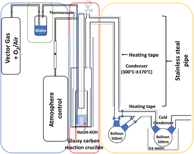
A specific setup, described in Fig. 1, has been developed to carry out the experiments in molten hydroxide media. It is divided into three main parts: (i) the incoming gas to control the reactor atmosphere and in-bath bubbling (blue zone in Fig. 1); (ii) the main reaction apparatus is made of a heated stainless steel reactor where a protective graphite crucible contains the glassy carbon crucible where the molten salt bath will react (red zone); and (iii) the exhaust gas circuit (yellow zone) connected to a mass spectrometer (MS). The sample insertion is performed once the bath is molten and thermally stabilized via an opening hatch on the top of the reactor.2.2 General reaction protocol
100 g of salt mixture (75% mol NaOH/25% mol KOH, Tmelting = 250 °C) are introduced into the glassy carbon crucible and heated at 400 °C. The controlled atmosphere on the bath surface is argon (flow rate 30 L h−1) and the bubbling gas is a mixture of 80% Ar and 20% O2, humidified by passing through water heated at 80 °C, allowing control of the humidity and acidity of the bath. The experiment starts when the sample is introduced in the molten salt through the hatch at the top of the reactor. In order to obtain a perfect immersion of the sample in the molten salt and avoid its reaction on the surface of the bath (i.e. a simple thermal degradation due to heat without interaction with the bath), it is placed into a gold cage (1.5 cm high, 1 cm wide and 1 cm thick), see ESI (Fig. S1†). The same sample mass is used for both organic acids and polymers, i.e. approximately 1 g. The carboxylic acids are frozen in liquid nitrogen before being placed into the gold cage for a rapid immersion into the molten salt. Butanoic acid (4 C), hexanoic acid (6 C) and decanoic acid (10 C) are successively introduced into the same bath. After each reaction, the gold cage is removed using an attached gold wire. It is then cleaned and filled with the subsequent carboxylic acid. After 5 hours of reaction, the furnace is switched off and left to cool down to room temperature. The solidified bath is then recovered; a part is collected for bath analysis after the reaction, the other part is dissolved in 500 ml of distilled water and filtrated to recover the solid residues for analysis. The three different kinds of sample (carboxylic acids, neoprene and polyethylene) are treated in three different baths. For specific experiments on exhaust gas and electrochemical in situ analysis, the bubbling gas is dried to avoid saturation of the mass spectrometer with water and to allow the evolution of the water content in the bath to be monitored electrochemically.2.3 Analysis
Linear sweep voltammetry (LSV) was used to follow the evolution of the acidity of the NaOH–KOH bath before and after the reaction. The bath was dried for 72 h at 400 °C under an atmosphere of dry Ar prior to adding the polymer.
3 Results and discussion
3.1 Solid residue analysis
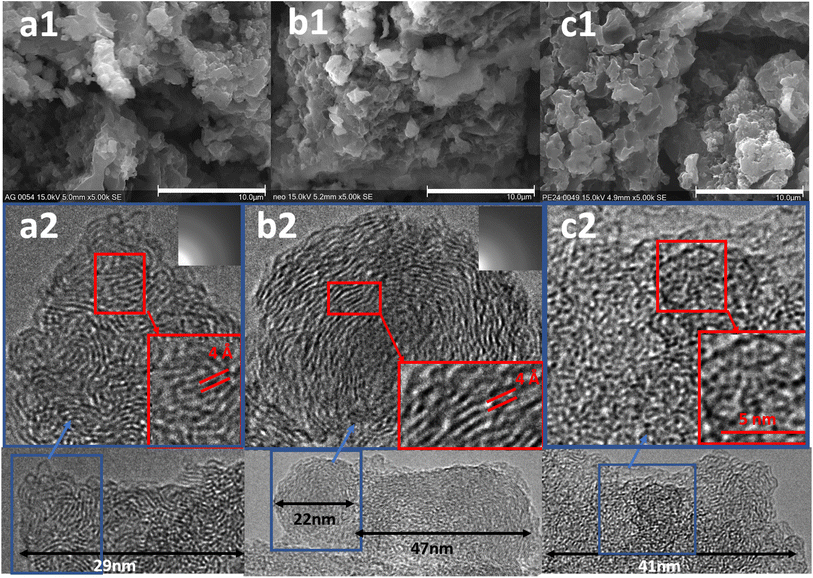
To give insight into the mechanisms of the organic solids decomposition reaction in the hydroxide baths, different kinds of organic compounds were used. First, two polymers were selected: polyethylene that contains only C–H chains and neoprene that also contains chlorine. Second, a series of short linear-chain organic acids was used (butanoic acid 4 C, hexanoic 6 C and decanoic 10 C) in order to determine if the decomposition products are similar between these two families of organic solids.SEM and TEM images of the solid residues obtained after treatment of (a) carboxylic acids, (b) neoprene, and (c) polyethylene are shown in Fig. 2. As the three carboxylic acids were treated consecutively in the same experiment, the sample contains a mixture of the three residues. In all cases, sheets of similar size and shape are observed (Fig. 2(a1)–(c1)). Furthermore, they resemble those observed by Lu et al.10 for boiled coffee beans treated in molten Na2CO3–K2CO3 at 800 °C, as well as by Gu et al.17 in the treatment of semi-coke at 500–700 °C in ZnCl2–KCl. The resulting sheets were identified as carbon graphite particles. As shown in the TEM images in Fig. 2(a2) and (b2) of carboxylic acid and neoprene residues, respectively, organised crystal planes are clearly observable in nanodomains indicating the area of the crystallised graphite sheets. The distance between the sheets is around 4 Å larger than what is expected in well-crystallized graphite (3.3–3.5 Å (ref. 18 and 19)). According to the literature, this difference can be explained by significant disruption to the ordered graphite structure, leading to warping, delamination, dislocations, and defects, as described in the article of Welham et al.20 In the polyethylene residue Fig. 2(c2), a disorder is observed with some areas of organised planes at the edge, indicating a more amorphous sample than the others.
To investigate further, IR analysis has been performed on the solid residues. Very similar spectra for carboxylic acids and neoprene are obtained after the reactions (Fig. 3b and d). None of the characteristic bands of the carboxylic acids (broad O–H stretching band at 3300–2500 cm−1, C![[double bond, length as m-dash]](https://www.rsc.org/images/entities/char_e001.gif) O stretching at 1700 cm−1, or O–H bending at 1430 cm−1) can be observed, nor the C–Cl stretching bands (800 cm−1) for the neoprene residue. In all cases, the characteristic C–H bands have disappeared and only vibrations associated with carbon bonds (stretching modes for C
O stretching at 1700 cm−1, or O–H bending at 1430 cm−1) can be observed, nor the C–Cl stretching bands (800 cm−1) for the neoprene residue. In all cases, the characteristic C–H bands have disappeared and only vibrations associated with carbon bonds (stretching modes for C![[double bond, length as m-dash]](https://www.rsc.org/images/entities/char_e001.gif) C at 1645 cm−1 and for C–C at 1200 and 1375 cm−1) can be slightly observed. Furthermore, the spectrum is similar to that of graphite residues obtained after the calcination of coconut shells at 1023 K.21
C at 1645 cm−1 and for C–C at 1200 and 1375 cm−1) can be slightly observed. Furthermore, the spectrum is similar to that of graphite residues obtained after the calcination of coconut shells at 1023 K.21
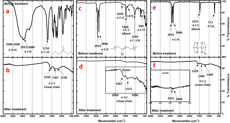 | ||
| Fig. 3 IR spectra of residues before (top) and after (bottom) treatment of carboxylic acids (a and b), neoprene (c and d), and polyethylene (e and f). | ||
For polyethylene (Fig. 3f), the C–H stretching and bending bands are strongly attenuated after treatment, revealing a profile very close to the neoprene spectrum after the reaction. However, even with weak intensity, the presence of these residual C–H stretching and bending bands observed after treatment indicates incomplete degradation. This explains the higher disorder observed using TEM on the corresponding residue sheets.
To better characterize the graphite particles, Raman analysis was carried out on the residue of neoprene after the reaction. The bands observed in the spectra are deconvoluted following the Kawakami method22 allowing us to attribute the different bands observed to different hybridizations of the carbons. The G band (corresponding to graphite) observed around 1580 cm−1 is attributed to the sp2 carbon bonded to the other carbons. The others bands appearing around 1360 cm−1 and 1680 cm−1, known as the D and D′ bands, respectively, correspond to a “defect structure” attributed to sp2 hybridized carbon at the edges of the graphite sheets. All the discussions below will use this nomenclature. The deconvolution of the Raman spectrum (Fig. 4) shows the presence of G, D and D′ bands at 1586, 1357 and 1693 cm−1 respectively. In addition, three bands corresponding to random contributions (R) according to Kawakami nomenclature were also extracted.22 These R bands would correspond to a random structure that is intermediate between graphite and an amorphous structure. The spectrum shape is much like the one of graphite produced by heat treatment (773 K) under CO2 of bamboo charcoal.22 It is worth noting that, in agreement with the IR results, no C–H bands were observed.
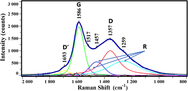 | ||
| Fig. 4 Raman spectrum of neoprene residue after treatment (thick blue line) and the deconvolution into D′ (yellow), G (green), R (magenta, blue, cyan) and D (red) bands. | ||
Moreover, part of the solidified salt was analyzed by X-ray diffraction after each treatment to check the salt stability. No carbonate phase was observed (Fig. 5), thus confirming the absence of CO2 dissolved in the bath. The large non-indexed peak at 26° corresponds to the polyethylene terephthalate (Mylar®) used as moisture protection of the XRD samples. Finally, the salts that mark the chloride absorption by the bath (KCl and NaCl) were not observed, probably due to the too small quantities formed. In our experimental conditions 1 g of treated neoprene contains approximately 0.34 g of chlorine which will be disolved in 100 g of bath, this ratio is below the limits of phases detection by powder XRD.
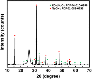 | ||
| Fig. 5 X-ray diffraction pattern of salt after treatment. KOH peaks denoted by green stars and NaOH peaks denoted by red stars. | ||
The diffraction pattern of the carboxylic acid residue presented in Fig. 6 shows two broad and weak peaks indicating low crystallinity or the presence of nanoparticles. This diffraction pattern is similar to the residue obtained by Lu et al.10 The peak located around 22° corresponds to the (002) reflection of a graphitic network and the one at 43° corresponds to a disordered stacking of the micrographite sheets.
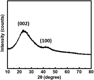 | ||
| Fig. 6 Powder X-ray diffraction pattern of carboxylic acid residue after treatment in molten hydroxide. The indexed peaks correspond to characteristic peaks of low-crystallinity graphite. | ||
In all cases, without considering the size of the initial organic chain, the degradation in molten hydroxides yields the formation of solid carbon residues. The composition of the latter is close to that of graphite obtained after the calcination of organic fibers like bamboo or coconuts shells.
Finally, complete mass balance cannot be performed due to observed losses during the recovery of the solid graphite fraction on the filter and in the filtrate, as detailed in the ESI.† However, an estimation is provided by comparing the experimental results of the CHONS elemental analysis (ESI†) of neoprene with the mass of residue obtained.
3.2 Gas and fumes analysis
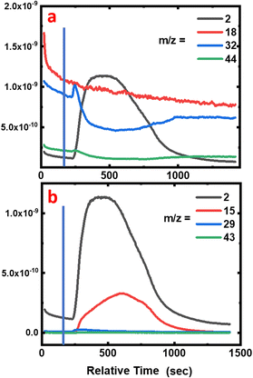
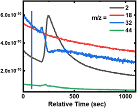
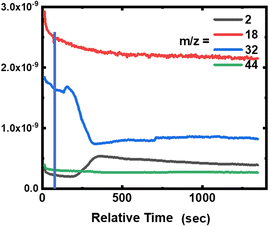
During the degradation experiment, the gas and fumes were analysed for each sample using mass spectrometry (Fig. 7a, 8 and 9, and Fig. S2 and S3 in the ESI†). It should be remembered that in this particular case, reactions are carried out in a dry atmosphere to avoid saturating the mass spectrometer with water. The striking points are the production of dihydrogen (m/z = 2), along with the decrease of O2 concentration (m/z = 32), but without any CO2 and gaseous H2O production (m/z = 44 and 18, respectively). Flandinet et al.12 had already observed the release of H2 during printed circuit board degradation and already proposed a possible recovery.No other species were observed after the polymers’ treatment. In the specific case of the neoprene, the chlorine present in the polymer is not visible in the gases emitted, which is in agreement with the study by C. Lin et al.7 that shows that chlorides produced during the reaction in molten salts are absorbed up to 99.99%. On the contrary, for carboxylic acids, the mass spectra reveal the presence of light alkanes in addition to dihydrogen (Fig. 7b and in the ESI, Fig. S2 and S3†). Due to their low vaporization temperature, a small fraction of acid is likely to be evaporated when introduced into the reaction chamber. In consequence, this small amount of acid undergoes partial thermal degradation in the reactor atmosphere, leading to the formation of these alkanes. This hypothesis is corroborated by the fact that the highest content of alkanes is observed for the degradation of butanoic acid, whose vaporization temperature is the lowest (Fig. 7b compared with the figures for hexanoic and decanoic acids given in the ESI, Fig. S2 and S3,† respectively). In addition, one must note from the mass spectra that the end of the reaction corresponds to the decrease of the H2 production associated with an increase of O2 in the atmosphere.
Furthermore, the absence of CO2 production during the reaction can be related to the solid graphite residue formation in the bath. Concerning the absence of H2O in the emitted gas, this points to possible water formation linked with the diminution of O2 content in the atmosphere during the reaction, and its dissolution in the dry hydroxide bath.
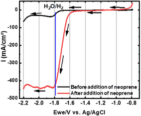
To confirm this hypothesis, in situ electrochemical analyses have been performed in the molten bath during a treatment of neoprene. The LSV voltammograms (Fig. 10) show a peak at −1.8 V corresponding to the reduction of H2O to H2. A significant increase in current, from −40 mA cm−2 to −450 mA cm−2, is observed after adding neoprene. This supports the theory of released water being dissolved in the bath and generating an increment of Lux-Flood acidity.23,24
3.3 Proposed reaction mechanisms in molten hydroxides
| ½O2 + 2OH− → O22− + H2O |
As a reminder, in molten hydroxide there are different species of oxygen ions (oxide, peroxide and superoxide) based on the following redox equations:23
| O22−(−I) + 2e− ⇌ 2O2−(−II) |
| O2−(−0,5) + e− ⇌ O22−(−I) |
The increase in the oxygen potential relative to oxygen activity, pO2−, leads to dismutation of peroxide ions:
| 3O22−(−I) + 2H2O(−II) → 2O2−(−0,5) + 4OH−(−II) |
| 2OH− ⇌ H2O + O2− |
The equilibrium of oxygen ions can be simplified by:
| 3O22−(−I) ⇌ 2O2−(−0,5) + 2O2−(−II) |
This shows that ion oxide is formed by the dissolution of oxygen (O2) to peroxide (O22−) and the dismutation of peroxide to oxide and superoxide (O2−).
| O2 + H2O → 4OH˙ |
| O22− + H2O → O2− + H2O2 |
| H2O2 → 2OH˙ |
Simplified by (with H2O2 intermediate species):
| O22− + H2O → 2OH˙ + O2− | (1) |
There are therefore various oxidising and radical species present in the hydroxide bath that can lead to various reactions (redox, acid–base and radical) depending on the material in the bath.23
The reaction products obtained here are similar to a non-oxidative cracking reaction as occurs in petrochemistry,28 where the mechanisms involved are radical in nature. The presence of hydroxyl radicals OH˙ in molten hydroxides makes such a mechanism possible.26,27 In accordance with the various analyses carried out during the experiments, as well as the end products obtained, an analogous mechanism can be proposed for the organic molecule degradation leading to H2 and carbon graphite formation:
| CxHy + OH˙ ⇌ CxHy−1˙ + H2O | (2) |
| CxHy−1˙ ⇌ CxHy−2 + H˙ |
| CxHy−(y+1)˙ ⇌ Cx + H˙ | (3) |
| H˙ + H˙ → H2 | (4) |
The consumption of oxygen can be explained by the formation of oxygen ion compounds in molten hydroxide; the reaction of oxygen and the peroxide ion with water forms hydroxyl radicals, as seen in eqn (1). Graphite is formed during the release of radical hydrogens from the carbon chains, as shown in eqn (3). Moreover, the chain radicals involved in eqn (2) allow longer chain recombination, as shown by Choudhary et al.28 following eqn (5).
| 2CxHy−1˙ ⇌ C2xH2y−2 | (5) |
Hence, graphite sheets can be formed, composed of many more carbons than the organic species they are derived from. The graphite, identified in the SEM image after the carboxylic acid degradation typifies this phenomenon.
To corroborate this mechanism, the identification of radicals species has been done using Electron Magnetic Resonance (EMR) analysis, and has thus been performed on a neoprene residue after treatment (Fig. 11). A very intense and extremely narrow line that can be well simulated with a single Lorentzian component is observed. The measured g-factor of 2.0036(4) is very close to the electron free value and indicates it is due to the carbon-based states, thus confirming the existence of carbon radicals in the sample. The half-width full-maximum ΔH½ of this resonance is only 0.74 mT, in agreement with reported graphite-like samples.29 At 10 K, further broadening is observed, suggesting the presence of more than one carbon-based species, i.e., at least two carbon radicals with different environments.
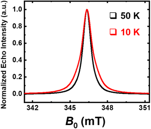 | ||
| Fig. 11 Echo-detected field-swept (ED-FS) spectra recorded at an X-band frequency (9.7 GHz) on neoprene residue after treatment; T = 50 K (black line) and T = 10 K (red line). | ||
In order to identify the nuclei coupled to the radical species, Hyperfine Sublevel Correlation (HYSCORE) spectroscopy has been used (Fig. 12).30 Indeed, 1H and 13C nuclear Larmor frequencies can be observed on the HYSCORE spectrum, both at 50 K and 10 K, on the (+,+) quadrant, for weakly coupled nuclei.
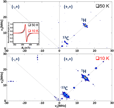 | ||
| Fig. 12 HYSCORE spectra recorded at an X-band frequency (9.7 GHz); T = 50 K (top) and T = 10 K (bottom). Inset: pseudo-modulation of the ED-FS as for Fig. 11. | ||
4 Conclusions
This study showed the degradation at 400 °C of low molar mass organics, carboxylic acids, and complex polymers in molten hydroxides. We were able to analyse and characterise the different reaction products (solid and gaseous) obtained during the degradation. These products, essentially graphite and dihydrogen, are the same for the reactions involving carboxylic acids, polyethylene and neoprene. The formation of graphite without the production of CO2 indicates that the reaction cannot correspond to an oxidation reaction as usually described in MSO processes. The analysis of the solid residues and previous studies show the presence of radical species in the molten hydroxide salts. We therefore propose a radical mechanism associated with this treatment to explain more accurately the reactions involved in molten hydroxide salts. It is important to work on the optimisation of the process, in particular the working temperature and the oxygen injection rate, as well as the salt/waste mass ratio depending on the nature of the waste. Overall this process, which makes it possible to treat microplastics, is a promising sustainable method for hydrogen and graphite recovery without greenhouse gas emissions.Author contributions
Conceptualization: F. Lecomte, A.-L. Rollet, S. Daviero-Minaud. Formal analysis: F. Lecomte, A. Moissette, A.-G. Porras-Guitérrez, G. Sicoli, M. Huve. Funding acquisition: A.-G. Porras-Guitérrez, A.-L. Rollet, S. Daviero-Minaud. Investigation: F. Lecomte, A.-G. Porras-Guitérrez, G. Sicoli, M. Huve. Methodology: F. Lecomte, A.-L. Rollet, S. Daviero-Minaud. Project administration: F. Lecomte, A.-L. Rollet, S. Daviero-Minaud. Supervision: A.-L. Rollet, S. Daviero-Minaud. Writing – original draft: F. Lecomte, S. Daviero-Minaud. Writing – review & editing: F. Lecomte, A.-L. Rollet, S. Daviero-Minaud, A. Moissette, A.-G. Porras-Guitérrez.Conflicts of interest
There are no conflicts to declare.Acknowledgements
This study was made possible by the CNRS in the context of F. Lecomte’s PhD thesis. The authors also thank the Chevreul Institute for XRD and microscopy platforms, LASIRE for the Raman spectroscopy experiments and EPR, PHENIX for the electrochemistry experiments, and UCCS for providing the various analysis platforms and laboratories.Notes and references
- Association of Plastic Manufacturers, Plastics – the Facts 2020, PlasticEurope, 2020, p. 16 Search PubMed.
- P. Kovařík, J. D. Navratil and J. John, Scientific and engineering literature mini review of molten salt oxidation for radioactive waste treatment and organic compound gasification as well as spent salt treatment, Sci. Technol. Nucl. Install., 2015, 2015, 407842 CrossRef.
- H.-C. Yang, Y.-J. Cho, J.-S. Yun and J.-H. Kim, Destruction of Halogenated Plastics in a Molten Salt Oxidation Reactor, Can. J. Chem. Eng., 2003, 81, 713–718 CrossRef CAS.
- A. Fedorov, Y. Chekryshkin and A. Gorbunov, Studies of Recycling of Poly(vinyl chloride) in Molten Na, Ca∥NO3, OH Systems, ISRN Chem. Eng., 2012, 768134 Search PubMed.
- H. C. Yang, Y. J. Cho, H. C. Eun and E. H. Kim, Destruction of chlorinated organic solvents in a two-stage molten salt oxidation reactor system, Chem. Eng. Sci., 2007, 62, 5137–5143 CrossRef CAS.
- Z. Ismagilov, M. Kerzhentsev and M. Adamson, Scientific Advances in Alternative Demilitarization Technologies, 2015, vol. 6, pp. 29–48 Search PubMed.
- C. Lin, Y. Chi, Y. Jin, X. Jiang, A. Buekens, Q. Zhang and J. Chen, Molten salt oxidation of organic hazardous waste with high salt content, Waste Manage. Res., 2018, 36, 140–148 CrossRef CAS PubMed.
- M. G. Adamson, P. C. Hsu, D. L. Hippie, K. G. Foster, R. W. Hopper and T. D. Ford, Organic waste processing using molten salt oxidation, High Temp. Mater. Process., 1998, 2, 559–580 CrossRef CAS.
- P. C. Hsu, K. G. Foster, T. D. Ford, P. H. Wallman, B. E. Watkins, C. O. Pruneda and M. G. Adamson, Treatment of solid wastes with molten salt oxidation, Waste Manage., 2000, 20, 363–368 CrossRef CAS.
- B. Lu, J. Zhou, Y. Song, H. Wang, W. Xiao and D. Wang, Molten-salt treatment of waste biomass for preparation of carbon with enhanced capacitive properties and electrocatalytic activity towards oxygen reduction, Faraday Discuss., 2016, 190, 147–159 RSC.
- K. Zeng, J. Li, Y. Xie, H. Yang, X. Yang, D. Zhong, W. Zhen, G. Flamant and H. Chen, Molten salt pyrolysis of biomass: The mechanism of volatile reforming and pyrolysis, Energy, 2020, 213, 118801 CrossRef CAS.
- L. Flandinet, F. Tedjar, V. Ghetta and J. Fouletier, Metals recovering from waste printed circuit boards (WPCBs) using molten salts, J. Hazard. Mater., 2012, 213–214, 485–490 CrossRef CAS PubMed.
- B. Trémillon, Chemistry in Non-Aqueous Solvents, 1967 Search PubMed.
- L. Chen, J. Yang, Y. Yang, J. Yu, X. Hu, W. Tao and Z. Wang, Solubility and dissolution behavior of ZrO2 in KF–AlF3 molten salts, J. Mol. Liq., 2022, 347, 118037 CrossRef CAS.
- L. C. Yu, C. Clark, X. Liu, A. Ronne, B. Layne, P. Halstenberg, F. Camino, D. Nykypanchuk, H. Zhong, M. Ge, W. K. Lee, S. Ghose, S. Dai, X. Xiao, J. F. Wishart and Y. C. K. Chen-Wiegart, Evolution of micro-pores in Ni-Cr alloys via molten salt dealloying, Sci. Rep., 2022, 12, 20785 CrossRef CAS PubMed.
- S. Dai, Y. Zheng, Y. Zhao, Y. Chen and D. Niu, Molten hydroxide for detoxification of chlorine-containing waste: Unraveling chlorine retention efficiency and chlorine salt enrichment, J. Environ. Sci., 2019, 82, 192–202 CrossRef CAS PubMed.
- Y. Gu, Y. Tang, L. Liu, Y. Zhang, Y. Gao, Y. Zhang, C. Yang and T. Liu, Semi-coke-based amorphous porous carbon synthesized by a molten salt assisted method for superior lithium storage, New J. Chem., 2023, 47, 2907–2913 RSC.
- J. Li, Y. Qin, Y. Chen, Y. Song and Z. Wang, HRTEM observation of morphological and structural evolution of aromatic fringes during the transition from coal to graphite, Carbon, 2022, 187, 133–144 CrossRef CAS.
- A. R. Kamali and J. Yang, Effect of molten salts on the structure, morphology and electrical conductivity of PET-derived carbon nanostructures, Polym. Degrad. Stab., 2020, 177, 109184 CrossRef CAS.
- N. J. Welham, V. Berbenni and P. G. Chapman, Effect of extended ball milling on graphite, J. Alloys Compd., 2003, 349, 255–263 CrossRef CAS.
- M. J. Rampe, B. Setiaji, W. Trisunaryanti and T. Triyono, Fabrication and Characterization of Carbon Composite From Coconut Shell Carbon, Indones. J. Chem., 2011, 11, 124–130 CrossRef.
- M. Kawakami, T. Karato, T. Takenaka and S. Yokoyama, Structure analysis of coke, wood charcoal and bamboo charcoal by Raman spectroscopy and their reaction rate with CO2, ISIJ Int., 2005, 45, 1027–1034 CrossRef CAS.
- B. Trémillon, Diagrammes d’équilibre potentiel-acidité (E-p02-) dans les sels et hydroxydes alcalins fondus, Pure Appl. Chem., 1971, 25, 395–428 CrossRef.
- H. Hayashi, S. Yoshizawa and Y. Ito, Studies on oxygen reduction in molten NaOH, Electrochim. Acta, 1983, 28, 149–153 CrossRef CAS.
- V. A. Volkovich, T. R. Griffiths, D. J. Fray and M. Fields, Increased oxidation of UO2 in molten alkali-metal carbonate based mixtures by increasing oxygen solubility and by controlled generation of superoxide ions, and evidence for a new sodium uranate, J. Chem. Soc., Faraday Trans., 1997, 93, 3819–3826 RSC.
- K. Takanabe, A. M. Khan, Y. Tang, L. Nguyen, A. Ziani, B. W. Jacobs, A. M. Elbaz, S. M. Sarathy and F. F. Tao, Integrated In Situ Characterization of a Molten Salt Catalyst Surface: Evidence of Sodium Peroxide and Hydroxyl Radical Formation, Angew. Chem., Int. Ed., 2017, 56, 10403–10407 CrossRef CAS PubMed.
- Z. Yao, X. Zhao and J. Li, Study on 1,2,3-Trichlorobenzene Destruction in a Binary (Na,K)2CO3 Molten Salt Oxidation System, Environ. Prog. Sustainable Energy, 2014, 33, 65–69 CrossRef CAS.
- T. V. Choudhary, E. Aksoylu and D. W. Goodman, Nonoxidative activation of methane, Catal. Rev.: Sci. Eng., 2003, 45, 151–203 CrossRef CAS.
- C. I. Smith, H. Miyaoka, T. Ichikawa, M. O. Jones, J. Harmer, W. Ishida, P. P. Edwards, Y. Kojima and H. Fuji, Electron spin resonance investigation of hydrogen absorption in ball-milled graphite, J. Phys. Chem. C, 2009, 113, 5409–5416 CrossRef CAS.
- J. Kausteklis, P. Cevc, D. Arčon, L. Nasi, D. Pontiroli, M. Mazzani and M. Riccò, Electron paramagnetic resonance study of nanostructured graphite, Phys. Rev. B: Condens. Matter Mater. Phys., 2011, 84, 125406 CrossRef.
Footnote |
| † Electronic supplementary information (ESI) available. See DOI: https://doi.org/10.1039/d3ra02537c |
| This journal is © The Royal Society of Chemistry 2023 |

