DOI:
10.1039/D3RA03117A
(Paper)
RSC Adv., 2023,
13, 19046-19057
Large-scale sonochemical fabrication of a Co3O4–CoFe2O4@MWCNT bifunctional electrocatalyst for enhanced OER/HER performances†
Received
10th May 2023
, Accepted 10th June 2023
First published on 22nd June 2023
Abstract
Herein, we have prepared a mixed-phase Co3O4–CoFe2O4@MWCNT nanocomposite through a cheap, large-scale, and facile ultrasonication route followed by annealing. The structural, morphological, and functional group analyses of the synthesized catalysts were performed by employing various characterization approaches such as X-ray diffraction (XRD), Fourier transform infrared spectroscopy (FTIR), and scanning electron microscopy (SEM). The resultant samples were tested for bifunctional electrocatalytic activity through various electrochemical techniques: cyclic voltammetry (CV), linear sweep voltammetry (LSV), and electrochemical impedance spectroscopy (EIS). The prepared Co3O4–CoFe2O4@MWCNT nanocomposite achieved a very high current density of 100 mA cm−2 at a lower (290 mV and 342 mV) overpotential (vs. RHE) and a smaller (166 mV dec−1 and 138 mV dec−1) Tafel slope in the oxygen evolution reaction (OER) and hydrogen evolution reaction (HER), respectively, compared to Co3O4–CoFe2O4. The excellent electrochemical activity of the as-prepared electrocatalyst was attributed to the uniform incorporation of Co3O4–CoFe2O4 over MWCNTs which provides high redox active sites, a greater surface area, better conductivity, and faster charge mobility. Furthermore, the enhanced electrochemical active surface, low charge-transfer resistance (Rct), and higher exchange current density (J0) of the Co3O4–CoFe2O4@MWCNT ternary composite are attributed to its superior behavior as a bifunctional electrocatalyst. Conclusively, this study demonstrates a novel and large-scale synthesis approach for bifunctional electrocatalysts with a high aspect ratio and abundance of active sites for high-potential energy applications.
1. Introduction
The world is trying its best to address both environmental issues and the energy crisis.1–8 Among the concerns, electrocatalytic water-splitting has received a lot of attention because of its low power threshold, greater efficiency, and low cost. The oxygen evolution reaction (OER) and the hydrogen evolution reaction (HER) take place at the anode and cathode of the electrochemical cell, respectively, to complete the electrochemical water-splitting process.9–11 Since the OER has slow rate kinetics and requires a high energy barrier to generate the reaction, it needs a very large overpotential and is inefficient.10 The HER process has been observed to have a faster rate of kinetics and require very low overpotential.12 Materials based on noble metals, such as ruthenium and iridium oxides for the oxygen evolution reaction and platinum for the hydrogen evolution reaction, exhibit impressive water-splitting efficiency, but they are not practical for widespread use due to their scarcity, high cost, and short longevity.13–15 Therefore, in the last few decades, there has been a lot of focus on developing and manufacturing electrocatalysts that are highly efficient, extremely accessible, and very cheap for high-efficiency water splitting. In particular, oxides, chalcogenides, phosphides, and metal–organic frameworks (MOFs) based on transition metals have gained popularity due to their superior performances and extended durability.16–19 Since the above-discussed state-of-the-art electrocatalysts only show performance in one of these areas, it is both difficult and exciting to design a dual functional catalyst that can concurrently catalyze both hydrogen evolution and oxygen evolution reaction.20
Iron (Fe), cobalt (Co), and nickel (Ni)-based electrocatalysts have been the subject of extensive research in electrocatalysis processes because of their affordability, widespread accessibility, ease of fabrication, and high efficiency during electrocatalytic processes.21,22 Particularly, bi- and trimetallic derivatives were found to be significantly superior to their monometallic analogs, possibly owing to improved permeability, strong interaction, and surface electrical state. Also, many cobalt and iron-based oxides have high water oxidation potentials, but surprisingly, only a small percentage of these materials are also bifunctional.23 Transition metal oxides (TMOs) have poor conductance and structural stability, which prevents them from performing their dual roles. Despite this, several research teams have found solutions to these problems by constructing TMO nanostructures with a massive proportion of exposed specific surface area, a high concentration of oxygen vacancies, and the exposure of particular crystal faces. This has allowed them to add strong HER activity to the impressive OER activity they already had.21,24,25
When looking at electrocatalysts for water splitting, cobalt ferrite (CoFe2O4) stands out as a possible option due to its low price and high catalytic activity.26 Catalysts based on cobalt are particularly attractive choices because the addition of other metals to their lattice structure has the potential to greatly increase their efficiency.26 Spinels based on cobalt are highly stable and can transport a charge, making them a promising substrate for low-cost, readily available electrocatalysts. In particular, CoFe2O4 with a partially inverted spinel structure has been studied for its potential as an OER catalyst, and its function can be modified via hybridization, morphology engineering, and size modification.27–29
Carbon-based water-splitting catalysts have gained a lot of popularity recently due to their cost effectiveness, easy accessibility, and little influence on the environment. One prominent factor is a multi-walled carbon nanotube (MWCNT)-based composite for bifunctional electrocatalytic activity as it enhances the material conductivity, increases mass and charge transfer, and provides an abundance of active sites for superior electrocatalytic activity.30 Owing to their superior aspect ratio, electrical conductivity, superior mechanical strength, and persistence, MWCNTs are an appealing carbonaceous material as a solid support for heterogeneous catalysts.31 Several methods have been suggested for fabricating mixed-phase binary and ternary nanocomposite (solid-state, sol–gel, hydrothermal, co-precipitation, etc.).32–35 The benefits of ultrasonic irradiation synthesis include large-scale synthesis, reduced reaction times, smaller product sizes, more precise control over synthesis conditions, less manufacturing costs, higher grade standards, less environmental effect, and so on.36 Acoustic cavitation, the process by which bubbles form, expand, and then combust as a result of ultrasound irradiation, is responsible for most of the chemical effects of this type of irradiation. The high energy density created by the bubble contents being heated by the liquid kinetic energy during the collapse can supply the necessary energy for chemical reactions. So, it is possible to consider it as an alternative to the more typical ways of synthesis.37,38
In this work, we have presented a simplified ultrasonication route for the fabrication of dual-phased Co3O4–CoFe2O4 and multi-walled carbon nanotubes loaded Co3O4–CoFe2O4 electrocatalyst. Multifunctional properties toward HER/OER reactions have been demonstrated by the optimized Co3O4–CoFe2O4@MWCNT composite by requiring very low overpotential to reach high current density. The synergistic effect between dual-phased Co3O4–CoFe2O4 and MWCNTs, beyond their primacy in structural and physical features, effectively boosts the electrocatalytic activity.
2. Experimental section
2.1. Required reagents
All chemical compounds; cobalt nitrate hexahydrate (Co(NO3)2·6H2O), polyethylene glycol (PEG), sodium carboxymethyl cellulose (CMC), ethanol (C2H5OH), multi-walled carbon nanotubes (MWCNTs), deionized water, and iron nitrate nonahydrate (Fe(NO3)3·9H2O) were procured from Sigma-Aldrich. There was only analytical-grade chemistry available and of the highest purity.
2.2. Preparation of Co3O4–CoFe2O4 binary nanocomposite
The dual-phased Co3O4–CoFe2O4 nanoparticles were synthesized via a simple sonochemical activation technique. Ultra-sonication was performed for 2 hours on a crucible containing iron nitrate nonahydrate (5.56 g), cobalt nitrate (2 g), and polyethylene glycol (20 g/24 mL of DI water). The crucible was then annealed for 2 hours at 700 °C. The resultant Co3O4–CoFe2O4 nanoparticles were obtained after annealing.
2.3. Preparation of Co3O4–CoFe2O4@MWCNT ternary nanocomposite
The ternary nanocomposite of multi-walled carbon nanotubes and mixed-phase Co3O4–CoFe2O4 was made using an easy-to-implement ultrasonication method. Firstly, 20 mg of MWCNTs were well-dispersed into deionized water by employing a sonication of one an hour. After that, 180 mg of the as-prepared Co3O4–CoFe2O4 sample was added slowly into the above MWCNTs suspension solution. Then the co-dissolved mixture was again treated with ultra-sonication for 120 minutes to obtain a homogenous mixture and excellent dispersion among the materials. The obtained sample was then dried at 80 °C and used for electrochemical performances.
2.4. Preparation of electrodes
The measured small pieces of carbon fiber cloth (CFC) were taken and then washed with ethanol and acetone, followed by distilled water. Afterward, electrocatalyst ink was made by dispersing 15 mg of as-synthesized materials in a 100 μL mixture of sodium carboxymethyl cellulose (CMC) binder and distilled water. The mixture was well-sonicated for 2 h. Electrodes for electrochemical assessments have been prepared by loading a CFC selective area (1 cm2) with 10 μL of electrocatalyst ink using the drop-casting method.
2.5. Characterization
The structural analysis and crystalline nature of as-fabricated materials were performed by using Lab XRD-6100 powder X-ray diffraction (XRD) using Cu-Kα as a source of radiation having λ = 1.54 Å and equipped with a position-sensitive detector. The morphological analysis of prepared samples was carried out using a scanning electron microscope (FEI Inspect S50; SEM). Fourier transform spectroscopy (FTIR) was deployed to examine the vibrational modes of prepared materials using a Shimadzu IR Affinity-1S spectrometer with KBr pellets approach.
2.6. Electrochemical water splitting assessment
The as-prepared electrocatalysts were tested in a conventional three-electrode setup in an alkaline solution of 1.0 M potassium hydroxide by using Gamry (INTERFACE 5000 E Potentiostat) electrochemical workstation to evaluate their electrocatalytic activity for bifunctional electrocatalytic activity. A mercury/mercury oxide (Hg/HgO) reference electrode, an electrocatalyst-modified carbon fiber cloth (CFC) working electrode, and a platinum (Pt) foil as a counter electrode completed the three-electrode system. First 200 cycles of cyclic voltammetry (CV) test were performed at 100 mV s−1 sweep rate to activate the material then these modified CFC electrodes undergo LSV tests to gain some insight into the overpotentials at varying current densities. The LSV for OER activity of as-prepared material was observed at varying potential ranges of 0.9 to 1.7 V (vs. RHE) at a scan rate of 5 mV s−1. To observe the HER performance of samples, a potential of range 0 to −0.65 V (vs. RHE) was applied at 5 mV s−1. The obtained potential values by using standard Hg/HgO electrodes were converted into reversible hydrogen electrode potentials (ERHE).39 The estimated pH for the alkaline solution used was 13.5. Furthermore, we have derived the Tafel slopes (log![[thin space (1/6-em)]](https://www.rsc.org/images/entities/char_2009.gif) j vs. OP) of nano-catalysts from their correlating LSV curves to better comprehend the reaction's viability. The cyclic voltammetry investigations were performed at five diverse scan rates in a non-faradic capacitive current range to estimate the double layer-capacitance (Cdl) values of as-fabricated Co3O4–CoFe2O4 and Co3O4–CoFe2O4@MWCNT catalysts. By further exploitation of the Cdl value, we have calculated the average Cdl values and electrochemically active surface area of materials by employing the formula; Average Cdl/Cs, where Cs is the specific capacitance of semiconducting materials (0.040 cm−2).40,41 Moreover, the EIS spectroscopic technique was used to assess the mass and charge transfer capabilities of CFC-modified electrocatalyst electrodes between solid and liquid interface resistance over a frequency range of 100
j vs. OP) of nano-catalysts from their correlating LSV curves to better comprehend the reaction's viability. The cyclic voltammetry investigations were performed at five diverse scan rates in a non-faradic capacitive current range to estimate the double layer-capacitance (Cdl) values of as-fabricated Co3O4–CoFe2O4 and Co3O4–CoFe2O4@MWCNT catalysts. By further exploitation of the Cdl value, we have calculated the average Cdl values and electrochemically active surface area of materials by employing the formula; Average Cdl/Cs, where Cs is the specific capacitance of semiconducting materials (0.040 cm−2).40,41 Moreover, the EIS spectroscopic technique was used to assess the mass and charge transfer capabilities of CFC-modified electrocatalyst electrodes between solid and liquid interface resistance over a frequency range of 100![[thin space (1/6-em)]](https://www.rsc.org/images/entities/char_2009.gif) 000 to 0.1 Hz. A Co3O4–CoFe2O4@MWCNT-loaded CFC substrate was then subjected to extensive chronopotentiometry testing (720 minutes) to determine the long-term performance and stability of the as-fabricated bifunctional electrocatalyst.
000 to 0.1 Hz. A Co3O4–CoFe2O4@MWCNT-loaded CFC substrate was then subjected to extensive chronopotentiometry testing (720 minutes) to determine the long-term performance and stability of the as-fabricated bifunctional electrocatalyst.
3. Results and discussion
3.1. Structural analysis
The synthesis of as-prepared samples was confirmed by using the powder-X-ray diffraction technique. The crystal structure, phase, and crystallite size analyses were also investigated by interpretation of XRD data from the obtained nanostructures. The XRD diffraction patterns of as-obtained Co3O4–CoFe2O4 and Co3O4–CoFe2O4@MWCNTs are presented in Fig. 1. The diffraction patterns present at 2θ values = 35.5°, 43.2°, 53.8°, and 56.5° correspond to (311), (400), (422), and (511) crystal planes of characteristic cobalt ferrite (JCPDS card no. 01-077-0426; space group Fd![[3 with combining macron]](https://www.rsc.org/images/entities/char_0033_0304.gif) m) with cubic crystal phase.42 The cobalt oxide (Co3O4) diffraction patterns were observed at 2θ values of 23.4°, 31.6°, and 45.5° can be assigned to (200), (220), and (400) crystal planes,43 well-matched with standard JCPDS card no. 01-071-0816. This confirms the presence of cubic phase Co3O4 nanoparticles in the produced sample and the formation of a mixed-phase CoFe2O4–Co3O4 nanostructure. The combination of two phases leads to enhanced electrocatalytic activity due to the combined synergistic effect of these nanostructures. The Co3O4–CoFe2O4@MWCNTs XRD plot shows a prominent hump at 2θ = 25.4°, which confirms the existence of MWCNTs44 in the Co3O4–CoFe2O4 sample. The crystallite size (D) of as-synthesized samples was estimated by using the Debye–Scherrer formula.45
m) with cubic crystal phase.42 The cobalt oxide (Co3O4) diffraction patterns were observed at 2θ values of 23.4°, 31.6°, and 45.5° can be assigned to (200), (220), and (400) crystal planes,43 well-matched with standard JCPDS card no. 01-071-0816. This confirms the presence of cubic phase Co3O4 nanoparticles in the produced sample and the formation of a mixed-phase CoFe2O4–Co3O4 nanostructure. The combination of two phases leads to enhanced electrocatalytic activity due to the combined synergistic effect of these nanostructures. The Co3O4–CoFe2O4@MWCNTs XRD plot shows a prominent hump at 2θ = 25.4°, which confirms the existence of MWCNTs44 in the Co3O4–CoFe2O4 sample. The crystallite size (D) of as-synthesized samples was estimated by using the Debye–Scherrer formula.45| |
 | (1) |
where β refers to full-width at half maximum (FWHM), λ is the used X-rays wavelength and θ is abbreviated as corresponding diffraction angles. Co3O4 and CoFe2O4 nanoparticles have an estimated crystallite size of 36.18 nm and 30.8 nm, respectively. In a Co3O4–CoFe2O4 binary composite, the presence of Co3O4 particles inhibited the growth of CoFe2O4 nanoparticles by impeding the propagation of particles with different alignment and dimensions and by blocking the movement of Co and Fe ions during the growth of CoFe2O4.
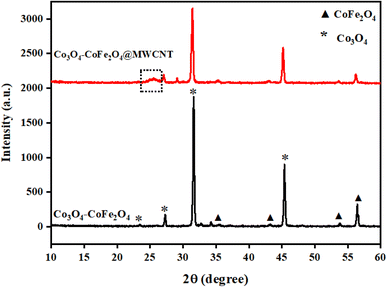 |
| | Fig. 1 XRD profiles of prepared samples: Co3O4–CoFe2O4 binary and Co3O4–CoFe2O4@MWCNT ternary nanocomposite. | |
After analyzing the XRD data, we used the following formula to determine the specific surface area (SSA) of the Co3O4–CoFe2O4 sample in its as-fabricated state.46
| |
 | (2) |
whereas,
Asp refers to the surface area of the particle and
Vparticle shows the volume of the particle. The specific surface area of the mixed-phase composition was calculated and presented in
Table 1. Results exhibit that in dual-phase composition CoFe
2O
4 provides a higher specific surface area as compared to Co
3O
4 particles. The increased specific area of CoFe
2O
4 may be attributable to the fact that it has a lesser crystallite size than Co
3O
4. An increase in surface area per unit mass may result from a smaller crystallite size because of the presence of additional grain boundaries and defects. This is because as crystallite size reduces, the surface area of each crystalline domain increases.
Table 1 XRD lattice parameters of mixed-phase Co3O4–CoFe2O4 particles
| S. no. |
Sample |
Crystal phase |
Lattice constant, a (Å) |
Lattice volume, V (Å3) |
Crystallite size, D (nm) |
Specific surface area (m2 g−1) |
| 1 |
Co3O4 |
Cubic |
8.06 |
523.6 |
36.18 |
610.17 |
| 2 |
CoFe2O4 |
Cubic |
8.3 |
571.78 |
30.8 |
687.16 |
3.2. FTIR study
Fourier transform infrared spectroscopic (FTIR) examination was executed for the determination of the bonding nature and identification of functional groups present in as-prepared materials. FTIR analysis was performed in the range of 4000–400 cm−1. The FTIR spectra of Co3O4–CoFe2O4 and Co3O4–CoFe2O4@MWCNT nanomaterials are presented in Fig. 2. The peaks located around 690 cm−1 in FTIR spectrum are corresponded to stretching vibration mode of metal–oxygen absorption band.47,48 The band around 1114 cm−1 is assigned to the cobalt–iron alloy system.49 These absorption bands confirm the preparation of dual-phase Co3O4–CoFe2O4 nanomaterial. The peaks around 873 cm−1 and 1427 cm−1 were referred to as vibrational modes of the C–O group which may be present due to the adsorption of atmospheric CO2.48,50 The broad bands located at 2926 cm−1 and 3665 cm−1 was assigned to the stretching vibrations of the O–H bond.49,50 The peak shifting was observed in the FTIR spectrum of Co3O4–CoFe2O4@MWCNT nanostructures, which confirms the synthesis of a ternary nanocomposite.
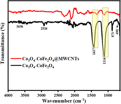 |
| | Fig. 2 Illustrates the FTIR spectra of fabricated materials in the 4000–400 cm−1 range. | |
3.3. Morphology studies
SEM analysis was performed to observe the morphologies of as-prepared Co3O4–CoFe2O4 and Co3O4–CoFe2O4@MWCNT electrocatalysts. Fig. 3(a) and (b) display the SEM profiles of Co3O4–CoFe2O4 and Co3O4–CoFe2O4@MWCNT, respectively, after fabrication. The SEM patterns in Fig. 3(a) show that the as-fabricated Co3O4–CoFe2O4 nanostructures have a rock-like amorphous morphology with defined lateral boundaries. The rock-like morphology is composed of basic disc-shaped units that combine together, giving rise to the observed structure. The average diameter of the rock-like amorphous structures was calculated and is approximately 3.5 μm. Furthermore, we have also calculated the average diameter of the voids within the composite material, which was found to be approximately 0.87 μm. Possibly as a result of the ultra-sonochemical fabrication of Co3O4–CoFe2O4@MWCNT, the nano-rocks of Co3O4–CoFe2O4 are evenly dispersed over the MWCNT in Fig. 3(b). With the help of ultra-sonication, nano-rock structures on nanotubes can interact and dissipate in a more homogeneous approach. And as seen in Fig. 3(a) and (b), there are several voids that may promote electrocatalytic activity.
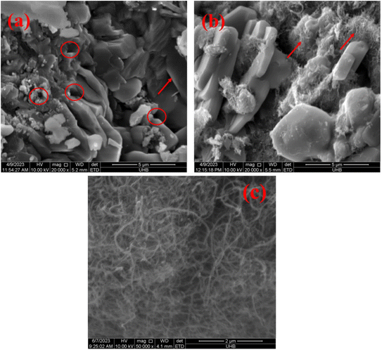 |
| | Fig. 3 SEM profiles of as-prepared samples: (a) Co3O4–CoFe2O4, (b) Co3O4–CoFe2O4@MWCNT nanostructures and (c) pure MWCNTs. | |
3.4. Preliminary electrochemical tests
The electrochemical stability of as-fabricated electrocatalysts was tested before their bifunctional electrocatalytic performance in terms of electrochemical active surface area, stability, and availability of active sites using the electrochemical method. The cyclic voltammetry tests were performed to analyze the redox peaks in as-produced electrocatalyst-loaded CFC substrate and unmodified CFC.51 The obtained cyclic voltammogram results of as-prepared Co3O4–CoFe2O4 and Co3O4–CoFe2O4@MWCNT nanostructures demonstrate clear broad redox peaks, while no redox peaks were observed in the case of bare CFC. Furthermore, 200 consecutive cycles of CV (Fig. S1†) at a sweep rate of 100 mV s−1 on the fabricated materials were carried out to evaluate the activity, stability, and aging of the fabricated materials. The area under the CV loop was directly related to charge (q*). The CV plots suggest no change in current density with a very small change in their shape. The charge (q*) associated with these successive cycles was determined and found to be constant with the increase in the number of cycles as shown in Fig. 4. The constant charge (q*) suggests that there was no potential loss of active sites, and all-fabricated samples are stable, effective, and have successive electrochemical activity for overall water splitting. The charge fraction  was estimated for all materials. The obtained fraction results were uniform for all prepared materials during successive 200 CV cycles. The charge fraction
  plots were presented in Fig. 3. The electrocatalytic sites were considered to be in direct relation with charge,52 therefore, the charge fraction analysis was carried out to check the overall water splitting performance of prepared electrocatalysts. Lastly, the above preliminary results demonstrate that materials have acquired the required stability and can be used for further electrochemical investigations.
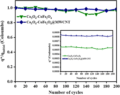 |
| | Fig. 4 Electrochemical measurements of the as-prepared sample,  fraction for concurrent 200 CV cycles at 100 mV s−1. The inlays in the figure demonstrate the charge (q*) evaluation of consecutive cycles. fraction for concurrent 200 CV cycles at 100 mV s−1. The inlays in the figure demonstrate the charge (q*) evaluation of consecutive cycles. | |
Moreover, to further investigate the performance of electrocatalysts, the surface concentration of atoms was calculated using cyclic voltammograms taken at a sweep rate of 20 mV s−1. The area under the reduction peak of the CV plot was considered and presented in Fig. S2.† The charge enclosed by the ternary composite reduction peak at 20 mV s−1 was found to be greater than the bare Co3O4–CoFe2O4 sample. The Co2+/Co3+ redox couple was linked by the charge enclosed in the reduction peak. And it was assumed that one cobalt atom could only chemically adsorb one oxygen atom. The Co3O4–CoFe2O4@MWCNT ternary composite has a higher reduction peak area than the other tested sample. The Co3O4–CoFe2O4@MWCNT electrocatalyst has a higher calculated surface concentration of atoms due to a greater reduction peak area as compared to Co3O4–CoFe2O4 and displayed in Table 2.
Table 2 Preliminary electrochemical parameters of as-prepared materials
| S. no. |
Parameters |
Co3O4–CoFe2O4 |
Co3O4–CoFe2O4@MWCNT |
| 1 |
Average Cdl (cm−2) |
0.13 |
0.26 |
| 2 |
ECSA (cm2) |
3.25 |
6.56 |
| 3 |
The surface concentration of atoms (×1015) |
1.31 |
6.24 |
The electrochemical active surface area (ECSA) of electrocatalysts was also considered in terms of electrocatalytic active sites by using the CV approach. The fabricated Co3O4–CoFe2O4 and Co3O4–CoFe2O4@MWCNT materials cyclic voltammograms were recorded for the non-faradaic region at varying scan rates (mV s−1) which are shown in Fig. S3.† The graphs between scan rate vs. current (A) were used for the estimation of ECSA of resultant samples and are presented in Fig. 5. The slope of these linear plots was considered to be Cdl. The average Cdl of fabricated materials was calculated and presented in Table 2. The higher average Cdl value of Co3O4–CoFe2O4@MWCNT shows that it provides a higher electroactive surface area for electrochemical performances. Furthermore, the ternary nanocomposite has greater available ECSA (6.56 cm2) as compared to its counterpart (3.25 cm2), which means it provides a highly porous shape and more exposed electroactive sites, which are responsible for excellent OER and HER performances.
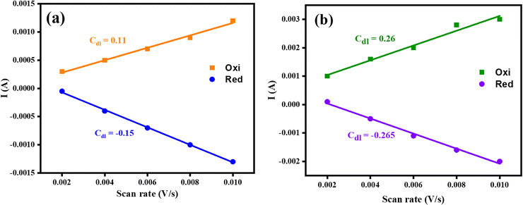 |
| | Fig. 5 Graphs of fabricated materials for the determination of ECSA; (a) mixed-phase Co3O4–CoFe2O4 (b) Co3O4–CoFe2O4@MWCNT electrocatalysts. | |
3.4.1. Electrocatalytic OER and HER performances. The OER activity of RuO2, Co3O4–CoFe2O4, and Co3O4–CoFe2O4@MWCNT samples was assessed by LSV tests at a sweeping rate of 5 mV s−1 with automatic iR compensation. For comparison, measurements of pure CFC and CFC-loaded sodium carboxymethyl cellulose (CMC) binder were also taken. The LSV curves of RuO2, Co3O4–CoFe2O4, and Co3O4–CoFe2O4@MWCNT obtained from the OER run are displayed in Fig. 6(a). In addition, a thorough analysis of the electrocatalyst performance was conducted to pinpoint the catalyst responsible for the observed current density of 100 mA cm−2. The observed overpotential for RuO2, Co3O4–CoFe2O4, and Co3O4–CoFe2O4@MWCNT 320 mV, 333 mV, and 290 mV, respectively, at 100 mV s−1 current density. The lower overpotential value of Co3O4–CoFe2O4@MWCNT reflects improved OER performance than the rest of the samples. Extensive data about the sample's electrocatalytic behavior and mechanism was obtained by calculating their Tafel slopes using the LSV polarization curves.
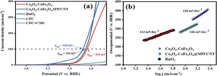 |
| | Fig. 6 (a) LSV polarization curves of CFC, CFC with the binder, RuO2, Co3O4–CoFe2O4, and Co3O4–CoFe2O4@MWCNT electrocatalysts at scan rate 5 mV s−1 for catalytic oxygen evolution reactions activity and (b) respective Tafel slopes. | |
Tafel slopes for RuO2, Co3O4–CoFe2O4, and Co3O4–CoFe2O4@MWCNT samples are 123, 220, and 166 mV dec−1, respectively (Fig. 6(b)). The smallest Tafel slope value of the Co3O4–CoFe2O4@MWCNT electrocatalyst reflects the improved electrocatalytic behavior and excellent kinetics toward OER. Tafel plots were also used to determine the OER mechanism taking place at the electrode surface.53 The OER mechanism involves the adsorption of hydroxyl groups on Co3O4–CoFe2O4@MWCNT active sites. Mainly 4 steps are involved which are depicted in eqn (3)–(6) during the whole mechanism. In the very first step, hydroxyl radicals are formed from hydroxyl anions on the active sites (M*) of the electrocatalyst. In the second step, the hydroxyl radicals were converted into reactive oxygen radicals (M–O*) with the removal of electrons and water molecules. Another nucleophilic hydroxyl radical attacks on M–O* and converts it into M–OOH* with the release of electrons during the third step. In the last step, the formed M–OOH* radical then again reacts with OH− anion to generate an oxygen molecule, metal active site, water molecule, and electron. In summary, the oxygen generation mechanism of Co3O4–CoFe2O4@MWCNT involves four hydroxyl anions with the release of two water molecules and electrons.54,55
| | |
OH− + M* ↔ M–OH* + e−
| (3) |
| | |
M–OH* + OH− ↔ M–O* + H2O + e−
| (4) |
| | |
M–O* + OH− ↔ M–OOH* + e−
| (5) |
| | |
M–OOH* + OH− ↔ oxygen↑ + M* + H2O + e−
| (6) |
Overall mechanism:
| | |
4(OH)− → O2↑ + 2H2O + e−
| (7) |
To evaluate the HER activity of samples, the HER polarization curves of Co3O4–CoFe2O4 and Co3O4–CoFe2O4@MWCNT were compared with those of a state-of-the-art Pt foil, bare CFC, and CFC deposited with the binder. The HER profiles of Pt, Co3O4–CoFe2O4, and Co3O4–CoFe2O4@MWCNT are exhibited in Fig. 7(a). It was found that pure CFC and CFC + CMC electrodes had negligible HER activity. Therefore, modified electrocatalysts performed normally during electrocatalytic reactions, regardless of the presence of CFC. The electrochemical performance of the prepared material was demonstrated by measuring the overpotential. The observed OP for Co3O4–CoFe2O4@MWCNT (342 mV) in hydrogen evolution experiments at current density 100 mA cm−2 is lower than pristine Co3O4–CoFe2O4 (419 mV) which demonstrates its high intrinsic HER activity. Tafel slopes were also calculated by using LSV data and shown in Fig. 7(b) which represents the stage in the electrocatalytic hydrogen generation process that establishes the rate and the likely mechanism. Tafel slope values were measured to be 69 mV dec−1 for Pt foil, 151 mV dec−1 for Co3O4–CoFe2O4, and 138 mV dec−1 for Co3O4–CoFe2O4@MWCNT. The smallest Tafel slope of CoFe2O4@MWCNT electrocatalyst then pristine Co3O4–CoFe2O4 exhibit that it has excellent reaction kinetics and electron transfer efficiency for hydrogen evolution reaction.
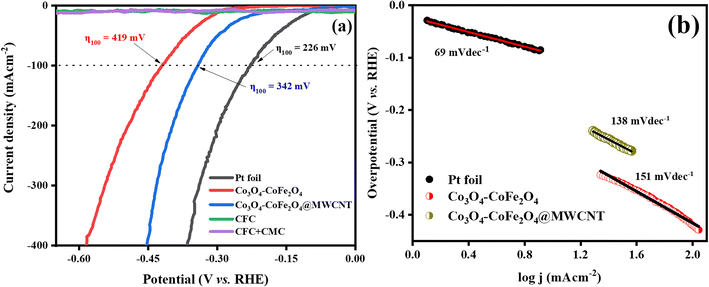 |
| | Fig. 7 (a) LSV polarization curve for HER activity of Pt, CFC, CFC with CMC binder, Co3O4–CoFe2O4, and Co3O4–CoFe2O4@MWCNT and their overpotential (η) values at j = 100 mA cm−2 and, (b) their corresponding Tafel slopes. | |
Mechanism analysis using Tafel slope data requires a discussion of the fundamental processes involved in H2 production. It is important to elaborate on the different basic processes that contribute to H2 evolution. Tafel slope values reveal the underlying mechanism occurring at the solid–liquid interface.56 The three simple steps from eqn (8)–(10) that makeup hydrogen production in alkaline media are as follows:
| | |
* + water mol. + e− → hydrogen radical + OH−
| (8) |
| | |
Hydrogen radical + water mol. + e− → hydrogen gas↑ + OH−
| (9) |
| | |
2H* → hydrogen gas↑ + 2(*)
| (10) |
whereas, H
2 adsorbed to metal sites is denoted by H*, where * stands for active sites. The adsorption of water molecules on the surface of materials to form hydrogen radicals is the first and most widely accepted step in the HER mechanism and is widely considered to be the rate-determining step. Following this, the activated H* will either adsorb another unit of water molecule during the Heyrovsky reaction. A total of two water molecules are used in the HER process to generate one hydrogen molecule [2H
2O + M* + 2e → H
2 + 2OH].
57 According to the slope value of the Tafel plot for Co
3O
4–CoFe
2O
4@MWCNT, the Heyrovsky reaction is the rate-determining step during the HER electrocatalysis process.
58 In this study, Co
3O
4–CoFe
2O
4@MWCNT demonstrated impressive catalytic activity toward HER. Insufficient adsorption of H
+ ions onto the surface of Co
3O
4–CoFe
2O
4 may contribute to the material's poor performance toward HER. In summary, the synthesis of MWCNTs incorporated dual-phased Co
3O
4–CoFe
2O
4 is a promising approach to enhance the electrocatalytic HER activity in an aqueous alkaline solution. OER and HER activity parameters of as-fabricated materials are presented in
Table 3.
Table 3 OER and HER activity parameters of as-fabricated materials
| S. no. |
Catalysts |
Tafel slope (mV dec−1) |
Overpotential (mV) η100 |
Onset potential (V) |
| OER |
HER |
OER |
HER |
OER |
HER |
| 1 |
Co3O4–CoFe2O4 |
220 |
151 |
333 |
419 |
1.50 |
0.376 |
| 2 |
Co3O4–CoFe2O4@MWCNT |
166 |
138 |
290 |
342 |
1.49 |
0.331 |
Mott–Schottky examination of the as-prepared materials was carried out as depicted in Fig. 8. Analysis was used to know more about the electronic properties of Co3O4–CoFe2O4 and Co3O4–CoFe2O4@MWCNT. And also, this analysis was very useful for the calculation of their flat band potentials values and carrier densities of as-fabricated materials.59 The potential for the flat band can be determined by plotting the linear portion of the curve against the X-axis of the Mott–Schottky plot.60
| |
 | (11) |
Flat-band potential (
Efb), specific capacitance (
C), electron charge (
e), dielectric constant (
ε), vacuum permittivity (
ε0), carrier density (
ND), applied potential (
E), Boltzmann constant (
k), and absolute temperature (
T) are all variables in this equation. The flat band potential of a material is the potential at which there is no net charge transfer between the material and the surrounding electrolyte.
61 The obtained
Efb for Co
3O
4–CoFe
2O
4 and Co
3O
4–CoFe
2O
4@MWCNT was 0.84 V and 0.73 V, respectively. A decrease in the flat band potential of Co
3O
4–CoFe
2O
4@MWCNT can result in a change in the electrochemical potential of the material, which can drive the creation of oxygen vacancies (OVs) through an electrochemical reaction. These vacancies can act as active sites for water oxidation, thereby improving the bifunctional electrocatalytic performance of the material. Obtained results show that the as-synthesized electrocatalyst is an efficient material as it has a higher value of charge carrier density which suggested the formation of oxygen vacancies in the material. The calculated carrier densities of both samples are given in
Table 4. The lower flat band potential and improvement in charge carrier density in Co
3O
4–CoFe
2O
4@MWCNT material was attributed to the formation of OVs in the as-prepared material which then act as electron donors.
62,63
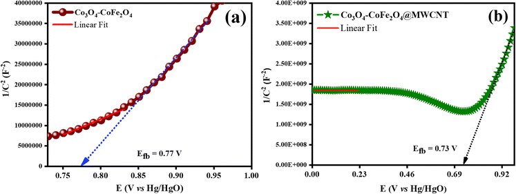 |
| | Fig. 8 Mott–Schottky profiles of as-synthesized catalysts for determination of flat band potential values: (a) Co3O4–CoFe2O4, and (b) Co3O4–CoFe2O4@MWCNT. | |
Table 4 EIS and Mott–Schottky results of different electrocatalysts synthesized in current study
| S. no. |
Catalysts |
Rct (Ω) |
Exchange current density (mA cm−2) |
Flat band potential (V) |
Carrier density (×1023 cm−3) |
| 1 |
Co3O4–CoFe2O4 |
2.87 |
2.24 |
0.77 |
8.63 |
| 2 |
Co3O4–CoFe2O4@MWCNT |
1.72 |
3.73 |
0.73 |
74.0 |
EIS analysis was performed on both samples to assume the kinetics of charge transfer between electrodes and electrolytes.64 Nyquist plots obtained from EIS measurements are displayed in Fig. 9. The Nyquist plot was taken over the frequency span of 10![[thin space (1/6-em)]](https://www.rsc.org/images/entities/char_2009.gif) 000 to 0.01 Hz. The experimental EIS data was depicted using a modified Randles circuit. The finalized circuit diagram appears in the inlays of Fig. 10.
000 to 0.01 Hz. The experimental EIS data was depicted using a modified Randles circuit. The finalized circuit diagram appears in the inlays of Fig. 10.
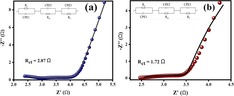 |
| | Fig. 9 EIS plots of as-prepared catalysts with fitted Randles circuit: (a) Co3O4–CoFe2O4, and (b) Co3O4–CoFe2O4@MWCNT electrocatalysts. | |
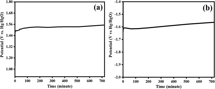 |
| | Fig. 10 Stability test for bifunctional Co3O4–CoFe2O4@MWCNT electrocatalyst at 100 mA cm−2 for an extended period 720 minutes; (a) OER and, (b) HER electrocatalysis. | |
This circuit displays the solution resistance Rs, the Rct refers to charge transfer resistance, and the film resistance Rf of the layer formed on the CFC. The performance of the HER and OER between the liquid phase and electrode is greatly influenced by the charge-transfer resistance (Rct), which is present in the high-end frequency region of the first semicircle. For Co3O4–CoFe2O4 and CoFe2O4@MWCNT, the calculated Rct values were 2.87 Ω and 1.72 Ω, respectively. The faster electron-transfer process at the surfaces of the Co3O4–CoFe2O4@MWCNT electrocatalysts was inferred from their lower Rct.65 The charge-trapping effect of MWCNTs, the decrease in flat-band potential, and the increase in charge-carrier density governed this decrease in charge-transfer resistance. The charge was able to flow more freely across the Co3O4–CoFe2O4@MWCNT/electrolyte interfaces as a result of this effect. The exchange current density (J0) was further analyzed to reveal the vital behavior of the entire water-splitting reaction and the consequences of charge-transfer resistance.66 The J0 was determined by using this formula: J0 = (R × T)/(A × n × F × q), where R stands for universal gas constant, T is abbreviated as the absolute temperature, the geometric area of the electrode is represented by A, F refers to Faraday's constant, q represents charge-transfer resistance and n denotes number of electrons in the charge being transferred. The Co3O4–CoFe2O4 binary and Co3O4–CoFe2O4@MWCNT ternary composite produced exchange current densities of 2.24 mA cm−2 and 3.73 mA cm−2, respectively. Co3O4–CoFe2O4@MWCNT electrocatalyst's high intrinsic activity was demonstrated by the greater value of exchange current density with faster charge transfer across the electrode interphase.
3.4.2. Stability tests. One more factor to consider when assessing the practical application of prepared materials as electrocatalyst is their long-term stability. Applying a steady current density of 100 mA cm−2 for 720 minutes was used to observe the long-term stability of the Co3O4–CoFe2O4@MWCNT electrocatalyst during OER and HER electrocatalysis. The tested electrocatalyst potential was not significantly impacted by the extended chronopotentiometry testing (Fig. 10), demonstrating the composite steadiness and outstanding stability for water splitting. The extended interconnected network of Co3O4–CoFe2O4 and MWCNT contributes to the material's outstanding long-term stability. Superior OER and HER bifunctional catalytic activity of the Co3O4–CoFe2O4/MWCNT catalyst may result from the MWCNT's high number of redox sites and enhanced electronic conduction. The comparison of current studies with previously reported literature is given in Table 5.
Table 5 Comparative studies of the bifunctional Co3O4–CoFe2O4@MWCNT electrocatalyst with previously reported literature
| Electrocatalysts |
Electrolyte |
Method of synthesis |
Overpotential (mV) |
Tafel slope (mV dec−1) |
Ref. |
| OER |
HER |
OER |
HER |
| Co3O4–CoFe2O4@MWCNT |
1 M KOH |
Ultrasonication |
η100 = 290 |
η100 = 342 |
166 |
138 |
This work |
| NF/Co3O4–CoFe2O4 |
0.1 M K3BO3 |
Solvothermal |
η10 = 215 |
— |
90 |
— |
67 |
| CoFe2O4/SWCNTs |
1 M KOH |
Hydrothermal |
η10 = 310 |
η10 = 263 |
85 |
46 |
68 |
| Co3O4/SWCNTs |
1 mol L−1 KOH |
Self-assembly |
η10 = 430 |
— |
104 |
— |
69 |
| Co3O4@CoWP |
1.0 M KOH |
Hydrothermal |
η10 = 269 |
η10 = 118 mV |
69 |
58 |
70 |
| Co3O4-ZIF8 |
1 M KOH |
Hydrothermal |
η1 = 270 |
— |
82 |
— |
71 |
| CoFe2O4 |
0.5 M H2SO4 |
Hydrothermal |
— |
η10 = 45 |
— |
35 |
72 |
| Cu2O–Co3O4/CN |
1 M KOH |
Hydrothermal |
η10 = 396 |
— |
281 |
— |
73 |
| SC-CoOx NPs |
0.1 M KOH |
Spray-coating |
300 |
350 |
54 |
133 |
74 |
4. Conclusion
In summary, the pristine Co3O4–CoFe2O4 and Co3O4–CoFe2O4@MWCNT electrocatalysts with nano-rocks-like amorphous structures were prepared by using sonochemical activation route for bifunctional OER/HER performances, employing three electrode setups. Co3O4–CoFe2O4@MWCNT/CFC electrodes exhibit outstanding OER and HER dual-functional electrocatalytic efficiency and stability which may be attributed to the presence of MWCNT which facilitates higher conductivity, superior charge transfer kinetics, and provides greater number of active sites for the water splitting reactions. The Co3O4–CoFe2O4@MWCNT catalyst shows superior electrocatalytic activity towards OER and HER with minimum overpotential required for attaining a high current density of 100 mA cm−2 as compared to its counterpart samples. The as-prepared Co3O4–CoFe2O4@MWCNT electrocatalyst has an improved electrochemical active surface area of 6.5625 cm2, minimum charge transfer resistance of 1.72 Ω, and a higher exchange current density of 3.73 mA cm−2 due to which it shows exceptional properties in water splitting with a higher rate kinetics. In this work, the catalyst with high stability and electrocatalytic activity has been designed for enhanced water splitting in an alkaline medium which is prepared through easy, large-scale, and cheap methods.
Conflicts of interest
All authors of this manuscript declare no conflict of interest being published in this journal.
Acknowledgements
The researchers would like to acknowledge Deanship of Scientific Research, Taif University for funding this work. Authors are also thankful to the Institute of Chemistry, BJ Campus, The Islamia University of Bahawalpur-Pakistan and HEC-Islamabad (Pakistan).
References
- H.-M. Yang and Z.-Y. Yuan, in Transition Metal-Based Electrocatalysts: Applications in Green Hydrogen Production and Storage, American Chemical Society, 2023, vol. 1435, ch. 1, pp. 1–20 Search PubMed
 .
. - B. Mohanty, P. Bhanja and B. K. Jena, Mater. Today Energy, 2022, 23, 100902 CrossRef CAS
 .
. - M. Kaleemullah, S. Yousaf, I. A. Alsafari, H. H. Somaily, J. Rahman, M. Shahid, M. Ashraf and M. F. Warsi, Int. J. Environ. Anal. Chem., 2022, 1–14, DOI:10.1080/03067319.2022.2141117
 .
. - A. Mustafa, I. A. Alsafari, H. H. Somaily, S. Yousaf, M. I. Din, J. Rahman, M. Shahid, M. Ashraf and M. F. Warsi, Phys. B, 2023, 648, 414404 CrossRef CAS
 .
. - S. Rafiq, M. Aadil, M. F. Warsi, S. Yousaf, M. T. Alotaibi, S. M. El-Bahy and M. Shahid, Ceram. Int., 2022, 48, 14596–14605 CrossRef CAS
 .
. - S. Rafiq, A. K. Alanazi, S. Bashir, A. Y. Elnaggar, G. A. M. Mersal, M. M. Ibrahim, S. Yousaf and K. Chaudhary, Phys. B, 2022, 638, 413931 CrossRef CAS
 .
. - S. Yousaf, M. Aadil, S. Zulfiqar, M. F. Warsi, P. O. Agboola, M. F. Aly Aboud and I. Shakir, J. Mater. Res. Technol., 2020, 9, 14158–14167 CrossRef CAS
 .
. - S. Yousaf, S. Zulfiqar, M. Shahid, A. Jamil, I. Shakir, P. O. Agboola and M. F. Warsi, Ceram. Int., 2020, 46, 14304–14310 CrossRef CAS
 .
. - S. Wang, A. Lu and C. J. Zhong, Nano Convergence, 2021, 8(1), 1–4 CrossRef CAS PubMed
 .
. - S. Wang, A. Lu and C.-J. Zhong, Nano Convergence, 2021, 8, 4 CrossRef CAS PubMed
 .
. - K. M. Katubi, A.-Z. Warsi, F. Aziz, Z. A. K. Khattak, M. F. Warsi, M. S. Al-Buriahi, Z. A. Alrowaili and S. Yousaf, Curr. Appl. Phys., 2023, 51, 80–90 CrossRef
 .
. - B. M. Stühmeier, M. R. Pietsch, J. N. Schwämmlein and H. A. Gasteiger, J. Electrochem. Soc., 2021, 168, 064516 CrossRef
 .
. - C. Li and J.-B. Baek, ACS Omega, 2020, 5, 31–40 CrossRef CAS PubMed
 .
. - M. Tahir, L. Pan, F. Idrees, X. Zhang, L. Wang, J.-J. Zou and Z. L. Wang, Nano Energy, 2017, 37, 136–157 CrossRef CAS
 .
. - J. Liu, J. Ma, Z. Zhang, Y. Qin, Y.-J. Wang, Y. Wang, R. Tan, X. Duan, T. Z. Tian and C. H. Zhang, J. Phys.: Mater., 2021, 4, 022004 CAS
 .
. - S. Sanati, A. Morsali and H. García, Energy Environ. Sci., 2022, 15, 3119–3151 RSC
 .
. - Y. Liu, Y. Guo, Y. Liu, Z. Wei, K. Wang and Z. Shi, Energy Fuels, 2023, 37, 2608–2630 CrossRef CAS
 .
. - Y. Wang, C. Yang, Z. Li, Z. Liang and G. Cao, Small, 2020, 16(25), 2001973 CrossRef CAS PubMed
 .
. - J. Li, J. Li, X. Zhou, Z. Xia, W. Gao, Y. Ma and Y. Qu, ACS Appl. Mater. Interfaces, 2016, 8, 10826–10834 CrossRef CAS PubMed
 .
. - Y. Lv, M. Chen, N. Suo, X. He and L. Cui, J. Electroanal. Chem., 2022, 927, 116979 CrossRef CAS
 .
. - F. Shahbazi Farahani, M. S. Rahmanifar, A. Noori, M. F. El-Kady, N. Hassani, M. Neek-Amal, R. B. Kaner and M. F. Mousavi, J. Am. Chem. Soc., 2022, 144, 3411–3428 CrossRef CAS PubMed
 .
. - X. Chen, J. Liu, T. Yuan, Z. Zhang, C. Song, S. Yang, X. Gao, N. Wang and L. Cui, Energy Mater., 2022, 2, 200028 Search PubMed
 .
. - D. H. Taffa, D. Balkenhohl, M. Amiri and M. Wark, Small Struct., 2023, 4(6), 2200263 CrossRef CAS
 .
. - J. Wang, X. Yue, Y. Yang, S. Sirisomboonchai, P. Wang, X. Ma, A. Abudula and G. Guan, J. Alloys Compd., 2020, 819, 153346 CrossRef CAS
 .
. - K. B. Ibrahim, M.-C. Tsai, S. A. Chala, M. K. Berihun, A. W. Kahsay, T. A. Berhe, W.-N. Su and B.-J. Hwang, J. Chin. Chem. Soc., 2019, 66, 829–865 CrossRef CAS
 .
. - J. Kubisztal and M. Kubisztal, Catalysts, 2022, 12, 21 CrossRef CAS
 .
. - X.-M. Liu, X. Cui, K. Dastafkan, H.-F. Wang, C. Tang, C. Zhao, A. Chen, C. He, M. Han and Q. Zhang, J. Energy Chem., 2021, 53, 290–302 CrossRef CAS
 .
. - S. Zhu, J. Lei, Y. Qin, L. Zhang and L. Lu, RSC Adv., 2019, 9, 13269–13274 RSC
 .
. - G. Ou, F. Wu, K. Huang, N. Hussain, D. Zu, H. Wei, B. Ge, H. Yao, L. Liu, H. Li, Y. Shi and H. Wu, ACS Appl. Mater. Interfaces, 2019, 11, 3978–3983 CrossRef PubMed
 .
. - A. Wang, X. Chen, L. Cheng, X. Shen, W. Zhu, L. Li and J. Pang, J. Mater. Chem. A, 2020, 8, 17621–17633 RSC
 .
. - Y. Meng, X. Huang, H. Lin, P. Zhang, Q. Gao and W. Li, Front. Chem., 2019, 7, 759 CrossRef CAS PubMed
 .
. - P. Ravi, V. Navakoteswara Rao, M. V. Shankar and M. Sathish, Mater. Today Energy, 2021, 21, 100779 CrossRef CAS
 .
. - R. Koutavarapu, S. G. Peera, T. G. Lee, C. R. Myla, D.-Y. Lee, J. Shim and S. K. Balasingam, Processes, 2021, 9, 1959 CrossRef CAS
 .
. - S. Chamani, M. Khatamian, N. S. Peighambardoust and U. Aydemir, ACS Omega, 2021, 6, 33024–33032 CrossRef CAS PubMed
 .
. - E. Sadeghi, N. S. Peighambardoust, S. Chamani and U. Aydemir, ACS Mater. Au, 2023, 3, 143–163 CrossRef CAS
 .
. - H. H. Al-Rasheed, M. Al Alshaikh, J. M. Khaled, N. S. Alharbi and A. El-Faham, J. Chem., 2016, 2016, 3464758 Search PubMed
 .
. - S. V. Sancheti and P. R. Gogate, Ultrason. Sonochem., 2017, 36, 527–543 CrossRef CAS PubMed
 .
. - N. F. Andrade Neto, A. B. Lima, R. R. Y. O. V. Wilson, T. C. N. Nicacio, M. R. D. Bomio and F. V. Motta, Mater. Sci. Semicond. Process., 2022, 139, 106311 CrossRef CAS
 .
. - K. Kawashima, R. A. Márquez, Y. J. Son, C. Guo, R. R. Vaidyula, L. A. Smith, C. E. Chukwuneke and C. B. Mullins, ACS Catal., 2023, 13, 1893–1898 CrossRef CAS
 .
. - A. Moysiadou, S. Lee, C.-S. Hsu, H. M. Chen and X. Hu, J. Am. Chem. Soc., 2020, 142, 11901–11914 CrossRef CAS PubMed
 .
. - T. A. Centeno and F. Stoeckli, J. Power Sources, 2006, 154, 314–320 CrossRef CAS
 .
. - L. Kafi-Ahmadi, S. Khademinia, M. Najafzadeh Nansa, A. A. Alemi, M. Mahdavi and A. Poursattar Marjani, J. Chil. Chem. Soc., 2020, 65, 4845–4848 CrossRef CAS
 .
. - H. Ebrahimzade, G. R. Khayati and M. Schaffie, Adv. Powder Technol., 2017, 28, 2779–2786 CrossRef CAS
 .
. - J. Li, y. Senbin, T. Li, X. Li, X. Yang and S. Ding, Procedia Eng., 2015, 102, 492–498 CrossRef CAS
 .
. - X. Sun, C. Zheng, F. Zhang, Y. Yang, G. Wu, A. Yu and N. Guan, J. Phys. Chem. C, 2009, 113, 16002–16008 CrossRef CAS
 .
. - M. Aghazadeh and F. Aghazadeh, Int. J. Bio-Inorg. Hybrid Nanomater., 2018, 7, 97–108 Search PubMed
 .
. - R. A. Bohara, N. D. Thorat, H. M. Yadav and S. H. Pawar, New J. Chem., 2014, 38, 2979–2986 RSC
 .
. - R. Bhargava, S. Khan, N. Ahmad and M. M. N. Ansari, AIP Conf. Proc., 2018, 1953 Search PubMed
 .
. - D. Karthickraja, S. Karthi, G. A. Kumar, D. K. Sardar, G. C. Dannangoda, K. S. Martirosyan and E. K. Girija, New J. Chem., 2019, 43, 13584–13593 RSC
 .
. - Y. Mao, B. Zhou and S. Peng, J. Mater. Sci.: Mater. Electron., 2020, 31, 9457–9467 CrossRef CAS
 .
. - S. Yousaf, S. Zulfiqar, H. H. Somaily, M. F. Warsi, A. Rasheed, M. Shahid and I. Ahmad, RSC Adv., 2022, 12, 23454–23465 RSC
 .
. - N.-U.-A. Babar, F. Hussain, M. N. Ashiq and K. S. Joya, ACS Appl. Energy Mater., 2021, 4, 8953–8968 CrossRef CAS
 .
. - A. Kapałka, G. Fóti and C. Comninellis, Electrochem. Commun., 2008, 10, 607–610 CrossRef
 .
. - N. Alwadai, S. Manzoor, S. R. Ejaz, R. Y. Khosa, S. Aman, M. Al-Buriahi, S. Alomairy, Z. Alrowaili, H. Somaily and M. Hayat, J. Mater. Sci.: Mater. Electron., 2022, 33, 13244–13254 CrossRef CAS
 .
. - P. V. Shinde, R. Samal and C. S. Rout, Trans. Tianjin Univ., 2022, 28, 80–88 CrossRef CAS
 .
. - Y. Jiang, J. Huang, B. Mao, T. An, J. Wang and M. Cao, Appl. Catal., B, 2021, 293, 120220 CrossRef CAS
 .
. - K. Srinivas, Y. Chen, Z. Su, B. Yu, M. Karpuraranjith, F. Ma, X. Wang, W. Zhang and D. Yang, Electrochim. Acta, 2022, 404, 139745 CrossRef CAS
 .
. - H. Zhong, C. A. Campos-Roldán, Y. Zhao, S. Zhang, Y. Feng and N. Alonso-Vante, Catalysts, 2018, 8, 559 CrossRef
 .
. - N. Lele, M. F. Bambo, E. M. Mmutlane and L. N. Dlamini, Emergent Mater., 2023, 6, 605–626 CrossRef CAS
 .
. - P. F. Ndione, E. L. Ratcliff, S. R. Dey, E. L. Warren, H. Peng, A. M. Holder, S. Lany, B. P. Gorman, M. M. Al-Jassim, T. G. Deutsch, A. Zakutayev and D. S. Ginley, ACS Omega, 2019, 4, 7436–7447 CrossRef CAS PubMed
 .
. - S. Al-Hilli and M. Willander, Sensors, 2009, 9, 7445–7480 CrossRef CAS PubMed
 .
. - S. Wang, T. He, P. Chen, A. Du, K. Ostrikov, W. Huang and L. Wang, Adv. Mater., 2020, 32, 2001385 CrossRef CAS PubMed
 .
. - X. Wu, F. E. Oropeza, D. den Boer, P. Kleinschmidt, T. Hannappel, D. G. H. Hetterscheid, E. J. M. Hensen and J. P. Hofmann, ChemPhotoChem, 2023, 7, e202200192 CrossRef CAS
 .
. - N. O. Laschuk, E. B. Easton and O. V. Zenkina, RSC Adv., 2021, 11, 27925–27936 RSC
 .
. - W. Zhang, B. Jia, X. Liu and T. Ma, SmartMat, 2022, 3, 5–34 CrossRef CAS
 .
. - Z. Zhang, Y. Wang, X. Leng, V. H. Crespi, F. Kang and R. Lv, ACS Appl. Energy Mater., 2018, 1, 1268–1275 CrossRef CAS
 .
. - M. Nozari-Asbemarz, M. Amiri, A. Khodayari, A. Bezaatpour, S. Nouhi, P. Hosseini, M. Wark, R. Boukherroub and S. Szunerits, ACS Appl. Energy Mater., 2021, 4, 2951–2959 CrossRef CAS
 .
. - Y. Ding, J. Zhao, W. Zhang, J. Zhang, X. Chen, F. Yang and X. Zhang, ACS Appl. Energy Mater., 2018, 2, 1026–1032 CrossRef
 .
. - J. Wu, Y. Xue, X. Yan, W. Yan, Q. Cheng and Y. Xie, Nano Res., 2012, 5, 521–530 CrossRef CAS
 .
. - L. Zhang, T. Zhang, K. Dai, L. Zhao, Q. Wei, B. Zhang and X. Xiang, RSC Adv., 2020, 10, 29326–29335 RSC
 .
. - G. Wei, Z. Zhou, X. Zhao and C. An, ACS Appl. Mater. Interfaces, 2019, 10(28), 23721 CrossRef PubMed
 .
. - J. Yin, L. Shen, Y. Li, M. Lu, K. Sun and P. Xi, J. Mater. Res., 2018, 33, 590–600 CrossRef CAS
 .
. - Z. A. Shaikh, N. Moiseev, A. Mikhaylov and S. Yüksel, Appl. Sci., 2021, 11, 9974 CrossRef CAS
 .
. - N.-U.-A. Babar, M. Asghar, F. Hussain and K. Joya, Mater. Today Energy, 2020, 17, 100434 CrossRef
 .
.
|
| This journal is © The Royal Society of Chemistry 2023 |
Click here to see how this site uses Cookies. View our privacy policy here.  Open Access Article
 a,
Muhammad Shahidb,
Iqbal Ahmad
 *c,
Sheraz Yousafa,
Amira Alazmid,
M. H. H. Mahmoude,
Islam H. El Azabf and
Muhammad Farooq Warsi
 *a
*a
![[thin space (1/6-em)]](https://www.rsc.org/images/entities/char_2009.gif) j vs. OP) of nano-catalysts from their correlating LSV curves to better comprehend the reaction's viability. The cyclic voltammetry investigations were performed at five diverse scan rates in a non-faradic capacitive current range to estimate the double layer-capacitance (Cdl) values of as-fabricated Co3O4–CoFe2O4 and Co3O4–CoFe2O4@MWCNT catalysts. By further exploitation of the Cdl value, we have calculated the average Cdl values and electrochemically active surface area of materials by employing the formula; Average Cdl/Cs, where Cs is the specific capacitance of semiconducting materials (0.040 cm−2).40,41 Moreover, the EIS spectroscopic technique was used to assess the mass and charge transfer capabilities of CFC-modified electrocatalyst electrodes between solid and liquid interface resistance over a frequency range of 100
j vs. OP) of nano-catalysts from their correlating LSV curves to better comprehend the reaction's viability. The cyclic voltammetry investigations were performed at five diverse scan rates in a non-faradic capacitive current range to estimate the double layer-capacitance (Cdl) values of as-fabricated Co3O4–CoFe2O4 and Co3O4–CoFe2O4@MWCNT catalysts. By further exploitation of the Cdl value, we have calculated the average Cdl values and electrochemically active surface area of materials by employing the formula; Average Cdl/Cs, where Cs is the specific capacitance of semiconducting materials (0.040 cm−2).40,41 Moreover, the EIS spectroscopic technique was used to assess the mass and charge transfer capabilities of CFC-modified electrocatalyst electrodes between solid and liquid interface resistance over a frequency range of 100![[thin space (1/6-em)]](https://www.rsc.org/images/entities/char_2009.gif) 000 to 0.1 Hz. A Co3O4–CoFe2O4@MWCNT-loaded CFC substrate was then subjected to extensive chronopotentiometry testing (720 minutes) to determine the long-term performance and stability of the as-fabricated bifunctional electrocatalyst.
000 to 0.1 Hz. A Co3O4–CoFe2O4@MWCNT-loaded CFC substrate was then subjected to extensive chronopotentiometry testing (720 minutes) to determine the long-term performance and stability of the as-fabricated bifunctional electrocatalyst.
![[3 with combining macron]](https://www.rsc.org/images/entities/char_0033_0304.gif) m) with cubic crystal phase.42 The cobalt oxide (Co3O4) diffraction patterns were observed at 2θ values of 23.4°, 31.6°, and 45.5° can be assigned to (200), (220), and (400) crystal planes,43 well-matched with standard JCPDS card no. 01-071-0816. This confirms the presence of cubic phase Co3O4 nanoparticles in the produced sample and the formation of a mixed-phase CoFe2O4–Co3O4 nanostructure. The combination of two phases leads to enhanced electrocatalytic activity due to the combined synergistic effect of these nanostructures. The Co3O4–CoFe2O4@MWCNTs XRD plot shows a prominent hump at 2θ = 25.4°, which confirms the existence of MWCNTs44 in the Co3O4–CoFe2O4 sample. The crystallite size (D) of as-synthesized samples was estimated by using the Debye–Scherrer formula.45
m) with cubic crystal phase.42 The cobalt oxide (Co3O4) diffraction patterns were observed at 2θ values of 23.4°, 31.6°, and 45.5° can be assigned to (200), (220), and (400) crystal planes,43 well-matched with standard JCPDS card no. 01-071-0816. This confirms the presence of cubic phase Co3O4 nanoparticles in the produced sample and the formation of a mixed-phase CoFe2O4–Co3O4 nanostructure. The combination of two phases leads to enhanced electrocatalytic activity due to the combined synergistic effect of these nanostructures. The Co3O4–CoFe2O4@MWCNTs XRD plot shows a prominent hump at 2θ = 25.4°, which confirms the existence of MWCNTs44 in the Co3O4–CoFe2O4 sample. The crystallite size (D) of as-synthesized samples was estimated by using the Debye–Scherrer formula.45


 was estimated for all materials. The obtained fraction results were uniform for all prepared materials during successive 200 CV cycles. The charge fraction
  plots were presented in Fig. 3. The electrocatalytic sites were considered to be in direct relation with charge,52 therefore, the charge fraction analysis was carried out to check the overall water splitting performance of prepared electrocatalysts. Lastly, the above preliminary results demonstrate that materials have acquired the required stability and can be used for further electrochemical investigations.


![[thin space (1/6-em)]](https://www.rsc.org/images/entities/char_2009.gif) 000 to 0.01 Hz. The experimental EIS data was depicted using a modified Randles circuit. The finalized circuit diagram appears in the inlays of Fig. 10.
000 to 0.01 Hz. The experimental EIS data was depicted using a modified Randles circuit. The finalized circuit diagram appears in the inlays of Fig. 10.

.
.
.
.
.
.
.
.
.
.
.
.
.
.
.
.
.
.
.
.
.
.
.
.
.
.
.
.
.
.
.
.
.
.
.
.
.
.
.
.
.
.
.
.
.
.
.
.
.
.
.
.
.
.
.
.
.
.
.
.
.
.
.
.
.
.
.
.
.
.
.
.
.
.


