DOI:
10.1039/D3RA03997H
(Paper)
RSC Adv., 2023,
13, 25920-25929
A compressible porous superhydrophobic material constructed by a multi-template high internal phase emulsion method for oil–water separation†
Received
14th June 2023
, Accepted 21st August 2023
First published on 30th August 2023
Abstract
Superhydrophobic porous materials exhibit remarkable stability and exceptional efficacy in combating marine oil spills and containing oily water discharges. This work employed the multi-template high internal phase emulsion method to fabricate a multi-template porous superhydrophobic foam (MTPSF). The materials were characterized through SEM, IR spectroscopy, contact angle measurement, and an electronic universal testing machine. Moreover, the materials' oil–water separation capability, reusability, and compressibility were thoroughly evaluated. The obtained results demonstrate that the material displays a water contact angle of 143° and an oil contact angle of approximately 0°, thus exhibiting superhydrophobic and superoleophilic properties. Consequently, it effectively facilitates the separation of oil slicks and heavy oil underwater. Furthermore, the MTPSF conforms to the second kinetic and Webber–Morris models concerning the oil absorption process. MTPSF exhibits an outstanding oil absorption capacity, ranging from 39.40 to 102.32 g g−1, while showcasing reliable reusability, high recovery efficiency, and excellent compressibility of up to 55%. The above exceptional attributes render the MTPSF highly suitable for oil–water separation applications.
1. Introduction
With the rapid development of human civilization and the economy, the demand for petroleum resources has been increasing. The ocean, which covers approximately 71% of the global area, contains abundant oil and gas resources and has gradually become a vital source of petroleum reserves. However, oil spills often occur during the exploration, extraction, transportation, processing, and storage of oil. Two oil spills1 occurred on June 4th and 17th, 2011, at the B and C platforms of the Penglai 19-3 oil field, resulting in a total discharge of 3300 barrels of crude oil into Bohai Bay. The oil spills not only have fatal impacts on the plankton,2–5 benthic invertebrates,6 and fish7,8 in the ocean, but they also pose a significant risk to nearby birds,9 mammals,10 and reptiles.11 The adverse effects of oil spills on marine ecosystems are severe and long-lasting. Plankton, which forms the base of the marine food chain, is especially vulnerable to oil spills. Oil spills can cause the death of planktonic organisms, which, in turn, affects the entire food chain, leading to the death of larger fish and marine mammals. Benthic invertebrates, which live on or under the ocean floor, are also highly susceptible to the toxic effects of oil spills. These organisms play a crucial role in the marine ecosystem, as they help recycle nutrients and maintain the marine environment's balance. The death of benthic invertebrates and plankton may lead to the collapse of the entire ecosystem. Oil spills also have a significant impact on the health and survival of birds, mammals, and reptiles that inhabit the coastlines and nearby islands. These animals are exposed to the toxic effects of oil spills when they come into contact with contaminated water or when they ingest contaminated prey. The ingestion of oil can cause damage to the internal organs and can lead to death.
Several commonly12 used methods for removing oil spills include physical absorption, chemical methods, thermal combustion, and biodegradation. Physical absorption13 involves using oil-absorbing materials to absorb, recover, and reuse the spilled oil. This method effectively removes oily wastewater from the marine environment, eliminating secondary pollution risks during subsequent treatment.14 Environmental experts consider physical absorption a highly efficient and feasible method for treating marine oil spills, owing to the high absorption efficiency and ease of oil recovery of absorbent materials. Hethnawi15 et al. have proposed a novel approach for synthesizing titanomagnetite (NTM) nanoparticles through a green method that involves varying the initial concentration and temperature of iron precursors. The resulting NTM nanoparticles have shown promising properties for oil spill remediation. The water contact angle of the nanoparticles was observed to be 141.86°, indicating their excellent hydrophobicity, while the maximum adsorption capacity for crude oil was determined to be 38 ± 2 g g−1. Guo16 et al. developed a novel method to synthesize graphene/hydroxypropyl methylcellulose composite aerogels (RGA/HPMCs) using a two-step hydrothermal reduction technique combined with ice templates. The resulting RGA/HPMCs possess high photothermal conversion efficiency, allowing them to rapidly increase their surface temperature by utilizing solar energy and significantly reducing the viscosity of crude oil for efficient adsorption. The saturation absorption capacity of RGA/HPMCs for crude oil was as high as 124.43 g g−1 and could be achieved within 22 minutes. The mechanical properties of the RGA/HPMCs were evaluated through 300 cycles of compression experiments under 70% strain, and no significant damage was observed. Moreover, the aerogels exhibited good reusability, with more than 90% of the initial adsorption capacity maintained after 5 cycles of absorption–extrusion desorption. The results suggest that RGA/HPMCs have great potential as a highly efficient and reusable adsorbent for the remediation of crude oil spills. Ouyang17 et al. have reported on the successful modification of sponge surfaces using poly(cyclotriphosphazene nitrile-co-bisphenol AF) (PZAF), resulting in a modified sponge (Sponge@PZAF) with a high water contact angle (WCA) of 153° and a high absorption capacity of 71.04 to 135.19 g g−1 for various greases and organic solvents within 30 s. The fine three-dimensional mesh structure of the sponge aids in the efficient and rapid adsorption of oil and grease, facilitating full saturation of the chamber. After 10 cycles of oil absorption–desorption recovery, Sponge@PZAF exhibited an absorption capacity as high as 69.76–132.44 g g−1, indicating excellent recoverability.
In previous work,18 our research group successfully developed superhydrophobic foam materials (OSPs@Foam) with a porous structure based on a high internal phase emulsion of Span 80 and oyster shell powders (OSPs) synergistic stabilizers. This compound showed excellent lipophilic hydrophobicity and absorption–desorption, enabling selective absorption and oil recovery from oil-containing water for effective oil–water separation. However, the material's mechanical properties were suboptimal, with a tendency towards rupture. In order to address this limitation, compressible superhydrophobic foams will be constructed using a multi-template high-internal-phase emulsion method in this study. Unlike the conventional single-template high-internal-phase emulsion method, which applies only a single substance as the pore-making template (usually pure water19,20 or organic solvents21), this study utilizes pure water, ethyl acetate (EAC), and OSPs as multiple templates. During the material fabrication, the water and EAC will be removed from the emulsion system through the drying procedure, and the OSPs will be eliminated through a reaction with hydrochloric acid. The application of multi-template high-internal phase emulsion method could construct more pores within the material and enhance its compressibility. The resulting material will be characterized for density, porosity, microstructure, chemical composition, wettability, and mechanical properties and tested for oil–water separation ability and reusability. This study aims to improve the existing foam material and enable its use in more demanding applications.
2. Experimental
2.1 Reagents and materials
Styrene (St), divinylbenzene (DVB), azobisisobutyronitrile (AIBN), span 80, and ethyl acetate (EAC) were purchased from Shanghai Macklin Biochemical Co., Ltd. Carbon tetrachloride (CTC), dichloromethane (DCM) and trichloromethane were obtained from Chengdu Kelong Chemical Co., Ltd. Hydrochloric acid and toluene were procured from Sinopharm Chemical Reagent Co., Ltd. Petroleum ether and methanol were sourced from Xilong Chemical Co., Ltd. Diesel and corn oil were bought locally in Zhanjiang, and oyster shell powders (OSPs18) were obtained by self-production. Distilled water was provided by the chemistry laboratory center of the esteemed institution.
2.2 Preparation of multi-template porous superhydrophobic foam (MTPSF)
A predetermined amount of 0.1 g DVB, St, and EAC were sequentially added to a glass sample vial, followed by the addition of 0.1 g Span 80, 0.02 g AIBN, and 0.05 g OSPs. The resulting mixture was sonicated for 5 minutes to ensure uniform mixing. Distilled water was then added in batches to the glass sample vial, with the vial vigorously shaken by hand after adding 1 mL to emulsify the emulsion in the system thoroughly. The resulting high internal phase emulsion was subjected to thermal treatment at 70 °C for 8 hours. The glass vial was carefully cracked open, and the material was extracted and dried in an oven at 60 °C. The sample was then subjected to Soxhlet extraction using anhydrous ethanol as the extractant to remove unreacted material and impurities. Finally, after drying, the desired material was obtained. Given that the obtained material was generated from a novel multi-template emulsion, we shall designate the resulting material as a multi-template porous superhydrophobic foam, specifically referred to as MTPSF (Table 1).
Table 1 The recipe of samples
| Samples |
St/g |
EAC/g |
Water/mL |
Acidifying |
| OSPs@Foam18 |
0.40 |
0 |
30 |
No |
| MTPSF-10 |
0.35 |
0.1 |
10 |
Yes |
| MTPSF-20 |
0.35 |
0.1 |
20 |
Yes |
| MTPSF-30 |
0.35 |
0.1 |
30 |
Yes |
2.3 Principles of MTPSF preparation
The preparation of the MTPSF involves the emulsification of organic phases (St, DVB, AIBN, EAC) in the presence of surfactant span 80 with ultra-pure water to form high internal phase emulsions, facilitated by the support provided by the OSPs at the oil–water interface. The free radical polymerization reaction of St and DVB is initiated by AIBN at 75 °C to construct the basic skeleton of MTPSF. Subsequently, the internal water and EAC escape from the material by heat during the drying step, leading to the construction of porous structures inside and on the surface of the material. The acid-soaking process causes the particles of OSPs embedded into the skeleton to react with hydrochloric acid, which in turn generates a large number of pores, as shown in Fig. 1.
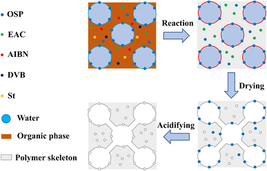 |
| | Fig. 1 The schematic diagram of preparing principle for multi-template porous material. | |
2.4 Characterization
The microstructure of MTPSF was observed with a high-resolution field-emission scanning electron microscope (FESEM, JEOL JEM-7500F). At the same time, the chemical composition of the samples was ascertained using Fourier transform infrared (FTIR) spectroscopy with a Thermo Fisher Nicolet 460 spectrometer. The compressive mechanical properties of MTPSF were assessed by employing an electronic universal testing machine (ELF 3220). The surface wettability of MTPSF was evaluated by utilizing a contact angle meter (CA, XG-CAMB3), with approximately 10 μL of distilled water or oil placed on the surface of each sample for testing.
2.5 Density and porosity
The drainage technique was employed to measure the MTPSF's volume (V). To ensure accuracy in the testing results, the surface of the material was carefully carved to facilitate the discharge of air bubbles. By submerging the material in a beaker filled with pure water through a glass rod and collecting the overflowing pure water, the volume of the material is calculated by the following equation.| |
 | (1) |
where, mw is the mass of overflowing water, ρw (997.8 g mL−1) is the density of pure water at room temperature.
An extremely sensitive one-millionth balance was applied to determine the mass (m) of the MTPSF, and the following formula calculated the density (ρ):
| |
 | (2) |
The porosity of MTPSF was determined through the replacement method,22 where methanol was implemented as the substitution liquid. The density (ρm) of methanol at 30 °C was approximately 0.7841 g mL−1, and the temperature was precisely controlled with a water bath. The smoothly cut samples (with initial mass M0 and initial volume V) were fully submerged in methanol, soaked for 10 minutes, and subsequently extracted. After eliminating excess liquid from the surface with paper towels, the MTPSF was weighed, and the resulting mass was recorded as M. The following formula evaluated the porosity (P):
| |
 | (3) |
2.6 Oil absorption capacity and recovery efficiency
To guarantee total absorption, an entire sample (with mass M0) was immersed in a range of test oils for 10 minutes, including ethanol, petroleum ether, DCM, trichloromethane, CTC, and EAC. After removal, the excess solution was removed from the surface with a tissue, and the sample was then weighed and documented as M2. The formula for computing oil absorption capacity (OAC) was shown below.| |
 | (4) |
We prepared a complete rectangular portion of sample (with mass M0) and exposed it to various oils for testing, including ethanol, petroleum ether, CTC, diesel, methanol, corn oil, and lubricant, left for 5 minutes, blotted the solution from the surface with dry papers, weighed, and recorded as M3. Subsequently, the oil-absorbed sample was centrifuged at 3000 rpm for 5 minutes, removed, weighted, and documented as M4. The formula for assessing recovery efficiency (RE) was shown below.
| |
 | (5) |
2.7 Adsorption kinetic curve
To obtain the adsorption kinetic curves of the materials, we employed the intermittent adsorption method. As demonstrated in Fig. 2, a simple device was utilized to regulate the contact time between the material and the oil. This apparatus consisted of a lifting table, a beaker containing the oil to be measured, and a platform held in place by an iron frame table that suspended a piece of iron screen in the air by cotton threads on which the material was placed.
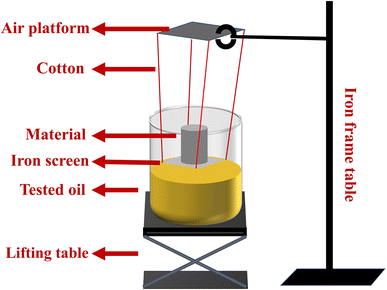 |
| | Fig. 2 The testing device for adsorption kinetic curves. | |
3. Results and discussion
3.1 Microstructure and pore size distribution
The microstructures of MTPSF-10, MTPSF-20, MTPSF-30, and OSPs@Foam are depicted in Fig. 3. All materials possess three-dimensional porous structures. The pore size statistics for MTPSF-10, MTPSF-20, MTPSF-30, and OSPs@Foam are presented in Table 2. As the amount of internal phase water increases, MTPSF's median and average values of pore diameters decrease, along with an increase in the cumulative frequency of pores with a diameter less than 3 μm. Compared to OSPs@Foam, MTPSF-30 exhibits even smaller median and average values, as well as larger cumulative frequency values for pores smaller than 3 μm. That can be attributed to the utilization of the multi-template high internal phase method in the production of MTPSF-30.
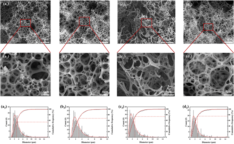 |
| | Fig. 3 (a1–d1) SEM images of MTPSF-10, MTPSF-20, OSPs@Foam and MTPSF-30; (a2–d2) expanded SEM images of MTPSF-10, MTPSF-20, OSPs@Foam and MTPSF-30; (a3–d3) pore size distribution and cumulative frequency of MTPSF-10, MTPSF-20, OSPs@Foam and MTPSF-30. | |
Table 2 The pore size distribution for samples
| Samples |
The diameter of pores |
| Mean (CI 95%a)/μm |
Median/μm |
<3 μm/% |
| Confidence interval (CI 95%) was calculated based on multiple experiments using the same sample aliquot. |
| MTPSF-10 |
3.29(0.228) |
2.77 |
54.3 |
| MTPSF-20 |
2.72(0.177) |
2.23 |
67.3 |
| OSPs@Foam |
2.53(0.176) |
2.06 |
74.0 |
| MTPSF-30 |
2.46(0.236) |
1.95 |
75.3 |
The pores in MTPSF originate from various mechanisms. Firstly, at high temperatures, the water inside the material can break through the material's skeleton, resulting in pore formation.23 The increased proportion of water in the internal phase leads to thinning the emulsion's organic phase film. This thinning makes the skeleton formed by the material thinner and more susceptible to breakage by the internal water. Additionally, a higher proportion of water means increased impact energy, favouring pore formation. Secondly, during the polymerization reaction of DVB and St, the organic phase undergoes a volume shrinkage from liquid to solid, resulting in the formation of numerous pores.24,25 As the proportion of water in the internal phase increases, the spherical shape of the aqueous droplets in the emulsion transitions into various polyhedral forms, and even rhombic dodecahedra,26 and the area of each facet of the droplet will be reduced accordingly. During monomer polymerization, each facet of the polyhedron has an equal probability of forming pores. Therefore, droplets with more facets generate more pores and smaller pore diameters. Thirdly, EAC in the organic phase can break through the material's skeleton at high temperatures, creating pores. Fourthly, OSPs embedded within the material's skeleton react with hydrochloric acid and migrate out of the material during subsequent acidification treatment. This migration leaves behind pores in the previously occupied OSP locations. In summary, the multi-template high internal phase method employed in MTPSF facilitates the construction of a larger number of pores with smaller diameters.
3.2 Chemical characteristics
Fig. 4 displays the infrared spectra of MTPSF-30, DVB and St. In the IR spectra of MTPSF-30, several notable peaks can be observed. The peaks at 3063 cm−1 and 3025 cm−1 correspond to the C–H stretching vibrations on the benzene ring. Peaks at 1605 cm−1, 1495 cm−1 and 1450 cm−1 are attributed to the backbone vibrations on the benzene ring. Furthermore, peaks at 880 cm−1, 755 cm−1 and 703 cm−1 indicate C–H out-of-plane bending vibrations. The appearance of the 880 cm−1 and 755 cm−1 peaks suggests that interposition substitution predominates in the benzene ring substitution of MTPSF-30. Additionally, DVB exhibits an 845 cm−1 peak, indicating the presence of para-substitution on DVB.
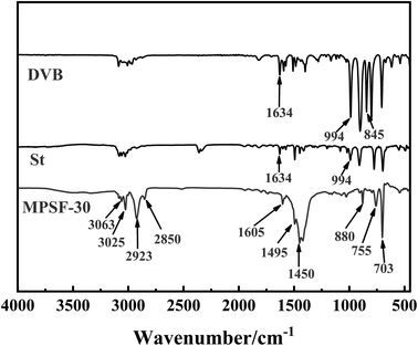 |
| | Fig. 4 FTIR spectra of MTPSF-30, DVB and St. | |
MTPSF-30 possesses two characteristic peaks, namely, 2923 cm−1 and 2850 cm−1, which arise from the stretching vibrations of hydrocarbon-saturated bonds. These peaks are absent in DVB and St. On the other hand, DVB and St exhibit distinctive peaks at 1634 cm−1 and 994 cm−1, which are not present in MTPSF-30. The peak at 1634 cm−1 corresponds to the stretching vibration of the carbon–carbon double bond, while the peak at 994 cm−1 is attributed to the C–H out-of-plane bending vibration. The presence of the 994 cm−1 peak suggests that DVB and St are monosubstituted. Based on the above information, it can be inferred that DVB and St produce MTPSF-30 via a polymerization reaction.
3.3 Physical characteristics
The densities, porosities, and internal phase proportions of MTPSF-10, MTPSF-20, MTPSF-30 and OSPs@Foam are listed in Table 3. As the internal phase proportion increases, the density of the material drops while the porosity goes up. Notably, MTPSF-30, produced through multi-template high internal phase method, exhibits a lower density and higher porosity compared with OSPs@Foam. An ideal superhydrophobic porous material should possess lower density and higher porosity in the field of oil–water separation. These characteristics facilitate the material's transport and enhance the oily wastewater's adsorption.
Table 3 The physical characteristics of materials
| Samples |
Density (CI 95%a)/g cm−3 |
Porosity (CI 95%a)/% |
Internal phase proportion/% |
| Confidence interval (CI 95%) was calculated based on multiple experiments on different samples. |
| MTPSF-10 |
0.0406(3.17 × 10⁻⁴) |
93.4(0.431) |
94.8 |
| MTPSF-20 |
0.0210(4.55 × 10⁻⁴) |
95.4(0.679) |
97.3 |
| MTPSF-30 |
0.0144(4.91 × 10⁻⁴) |
97.4(0.652) |
98.2 |
| OSPs@Foam |
0.0159(5.56 × 10⁻⁴) |
96.3(0.445) |
98.2 |
3.4 Wettability
Fig. 5 presents the water contact angles of MTPSF-30, MTPSF-20, MTPSF-10 and OSPs@Foam as 143°, 142°, 138° and 151°, respectively, showcasing their superhydrophobic–superoleophilic properties with water sliding angle of 6° and an oil contact angle of approximately 0°. Notably, MTPSF derived from improvements of OSPs@Foam exhibit a minor decline in water contact angle, likely due to the incorporation of OSPs, which produce the rough surface structure of foams. Subsequently, the surface roughness is compromised by acidizing, which reduces the water contact angle.
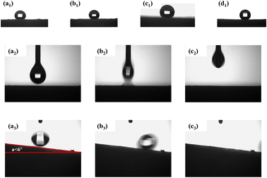 |
| | Fig. 5 (a1–d1) Water contact angle of MTPSF-10, MTPSF-20, MTPSF-30 and OSPs@Foam; (a2–c2) ethanol contact angle of MTPSF-30; (a3–c3) water sliding angle of MTPSF-30. | |
3.5 Oil–water separation
In Fig. 6(a) and (b), we conducted a test wherein ethanol treated with methyl yellow was dropped onto the surface of the material, resulting in the rapid orange-yellow dyeing of the surface, indicating the material's lipophilic properties. Conversely, when distilled water was dropped onto the material's surface, the formation of water droplets was observed. Only slight tilting of the material led to the rapid rolling off of the water droplets, demonstrating the material's hydrophobic characteristics.
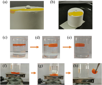 |
| | Fig. 6 (a and b) Schematic diagram of water and ethanol drops on the surface of MTPSF-30; (c–e) MTPSF-30 absorbed toluene on the water surface; (f–h) MTPSF-30 absorbed CTC under the water. | |
The oil–water separation capability of MTPSF was assessed using two distinct models: the floating light oil model and the submerged heavy oil model. As demonstrated in Fig. 6(c)–(e), MTPSF absorbs toluene stained with Sudan II on the water surface, clarifying the oily water body within two minutes. Similarly, Fig. 6(f)–(h) depicts the material's buoyancy overcoming by tweezers to make contact with the CTC stained with Sudan II under the water surface for adsorption. Upon contact with CTC, the absorbed CTC squeezes out the air, forming bubbles in the water body and completely removing the CTC in under a minute, leaving behind clear water. These oil–water separation experiments confirm that MTPSF possesses exceptional oil–water separation abilities, highlighting their potential for widespread applications.
3.6 Oil absorption capacity
The oil absorption capacity (OAC) is a crucial characteristic to assess the ability of materials to absorb oil, and the OAC of different samples (MTPSF-10, MTPSF-20, MTPSF-30 and OSPs@Foam) for various oils is shown in Fig. 7. The OAC of the samples ranged from 39.40 to 102.32 g g−1, with MTPSF-30 exhibiting excellent oil absorption ability. MTPSF-30's OAC for CTC reached an impressive 102.32 g g−1, which was on account of the large density of CTC. A comparison of MTPSF-10, MTPSF-20 and MTPSF-30 showed that the OAC of the material rose with higher water content in the internal phase, which provides more space for the oil to be absorbed.27 On the other hand, a comparison of MTPSF-30 and OSPs@Foam revealed that constructing more pores led to a more powerful oil-absorbing capacity. Table 4 compares the OAC of MTPSF with other materials, and it is evident that MTPSF has superior oil-absorbing capability.
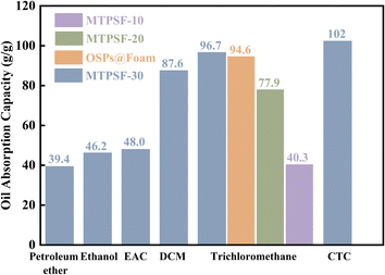 |
| | Fig. 7 The oil absorption capacity of samples for various oils. | |
Table 4 Comparison among oil absorption capacities of other materials
| Reference |
Materials |
Oils |
OAC (g g−1) |
| Zhu28 |
Modified wood aerogel |
DCM |
25.1 |
| Satria29 |
PFU-Fe-SA |
DCM |
38.0 |
| Bi30 |
Spongy graphene |
DCM |
86.0 |
| Yang31 |
PU sponge |
Petroleum ether |
25.0 |
| Wang32 |
PDMS-SiO2@PU-Econea sponge |
Ethanol |
42.0 |
| Gharehasanloo33 |
CS@PLA foam |
Trichloromethane |
48.0 |
| This work |
MTPSF |
DCM |
87.6 |
| Petroleum ether |
39.4 |
| Ethanol |
46.2 |
| Trichloromethane |
96.7 |
3.7 Recovery efficiency
The recovery efficiency of MTPSF was evaluated for different types and viscosities of oils, which is a crucial parameter for measuring the material's ability to recover oil. The results are illustrated in Fig. 8, and the recovery efficiency ranges from 85.67% to 99.12%. Notably, the recovery efficiency of MTPSF for petroleum ether was an outstanding 99.12%, whereas for lubricating oil and corn oil, the values were only 85.67% and 86.76%, respectively. This discrepancy can be attributed to the oil's viscosity, as oils with higher viscosity are more challenging to desorb through centrifugation, leading to higher recovery costs. High recovery efficiency is an important factor in reducing recovery costs and increasing the practical application value of the material.
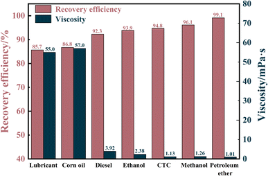 |
| | Fig. 8 Recovery efficiency of MTPSF-30 for different viscosity oils. | |
3.8 Reusability
The absorbed oil inside the MTPSF can be recovered by simple centrifugation and squeezing. The results of repeated adsorption–desorption cycles of MTPSF for ethanol and diesel by centrifugation are presented in Fig. 9(e) and (f). In Fig. 9(e), the initial oil absorption capacity of MTPSF-30 for ethanol is measured at 36.1 g g−1. This value significantly differs from the OAC shown in Fig. 7 (46.2 g g−1). Such discrepancies can be attributed to two key factors. One is that the materials used in the two experiments were cut differently. The material used in Fig. 7 was cut into cylinders, while the material used in Fig. 9(e) was cut into rectangles. The second is that even though these materials were prepared by the same recipe and preparation method, there were still large fluctuations in the multiplicity of their absorption of ethanol. The material underwent ten cycles of the adsorption–desorption process, exhibiting its durability and resistance to structural damage. After ten cycles, the OAC of the material dropped by 13.0% and 13.6% for ethanol and diesel, respectively, resulting in residual rates of 2.36 g g−1 and 2.71 g g−1 for ethanol and diesel inside the material. The decrease in OAC can be attributed to the shrinkage of pores inside the material during centrifugal desorption. Additionally, diesel has a larger viscosity than ethanol, allowing its retention inside the material during centrifugal desorption, which accumulates gradually during cycling. However, the MTPSF-30's oil absorption capacity does not decrease dramatically and can desorb most oil absorbed inside the material. Compared to other studies,34,35 MTPSF demonstrates excellent reusability and practicality in the field of oil–water separation, mainly due to their high number of cycles.
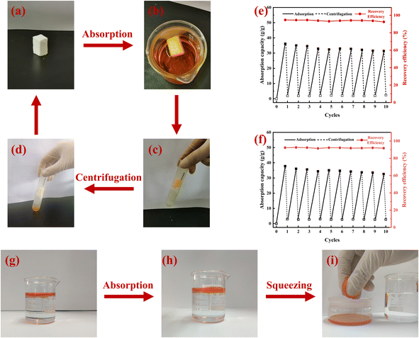 |
| | Fig. 9 (a–d) Absorption–desorption cycles of MTPSF-30 by centrifugation; (e and f) reusability of MTPSF-30 for the absorption of ethanol and diesel within 10 cycles by centrifugation; (g–i) absorption–desorption of MTPSF-30 by squeezing. | |
3.9 Adsorption kinetics
To eliminate the influence of oil density on the adsorption of MTPSF-30, we introduce the parameter K, which represents the progress of adsorption. Its expression is shown in eqn (6),| |
 | (6) |
where, Qe represents the saturation absorption capacity of MTPSF-30, and Qt represents the absorption capacity of MTPSF-30 at time t. We conducted adsorption experiments using the intermittent adsorption method and measured the adsorption kinetic curves of MTPSF-30 for various oils, as depicted in Fig. 10. Over time, the adsorption curve of MTPSF-30 became flat, and the adsorption rate decreased sharply. The saturation adsorption time of MTPSF-30 for the oil under test ranged between 195 and 7775 seconds. This saturation adsorption time was observed to increase with the oil's viscosity. A comparison of the adsorption kinetic curves for MTPSF-30 and OSPs@Foam showed that MTPSF-30's shorter saturation time for ethanol adsorption could be attributed to its higher pore quantity, which would offer a stronger capillary force for oil adsorption.
 |
| | Fig. 10 (a and b) Adsorption kinetic curves of MTPSF-30 for various oils; (c) ethanol adsorption kinetic curve of MTPSF-30 and OSPs@Foam. | |
When the material comes into contact with the oil, the initial oil molecules in contact with the material are adsorbed first. These molecules enter the interior of the material through capillary forces. However, oil molecules with higher viscosity, experiencing stronger intermolecular forces, cannot quickly penetrate the material's interior and tend to remain on the surface, reducing the effective contact area and significantly decreasing the adsorption rate. Additionally, as the oil molecules on the material's surface are adsorbed, molecules from other areas migrate to the surface, enabling subsequent adsorption. Higher oil viscosity leads to stronger intermolecular forces between the oil molecules, resulting in a slower migration rate and lower adsorption rate of the material for the oil. Moreover, oil with higher viscosity that enters the material demonstrates a relatively slower diffusion rate within the pores, which consequently results in a lower adsorption rate by the material for oils of higher viscosity.
To simulate the adsorption process of MTPSF-30, we employed the pseudo-first-order kinetics, pseudo-second-order kinetics, Elovich, and Webber–Morris models. The simulation results, presented in Fig. 11 and ESI,† indicated that the adsorption process of MTPSF-30 aligns more closely with the second-order sorption kinetics and Webber–Morris models, with R2 values exceeding 0.9477 for all oils. Webber–Morris model36 presented in this study describes a process in which the adsorption rate is influenced by intraparticle or film diffusion. The model equation is as follows:
where,
Qt represents the absorption capacity of the material at time
t,
ki is the intraparticle diffusion rate constant, and
C is the intercept on the vertical axis.
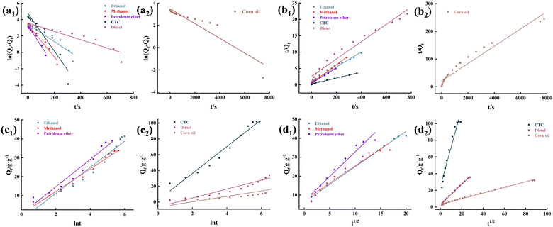 |
| | Fig. 11 (a1 and a2) The pseudo-first-order kinetics model of oil sorption on MTPSF-30; (b1 and b2) the pseudo-second-order kinetics model of oil sorption on MTPSF-30; (c1 and c2) the Elovich model of oil sorption on MTPSF-30; (d1 and d2) the Webber–Morris model of oil sorption on MTPSF-30. | |
The fitted data demonstrated that the plotted straight line for the MTPSF does not pass through the origin, indicating that C is not 0. This observation implies that the absorption of MPTSF for oil is restricted by both the diffusion rate through the film and the internal diffusion rate. Since MTPSF has an impressive porosity and can be considered as an internally empty material. Oil molecules that penetrate the interior of the MPTSF-30 undergo lateral or longitudinal diffusion driven by capillary forces and intermolecular forces, eventually reaching the centre and top of the material. Furthermore, as MTPSF absorbs more viscous oil, the ki value decreases, thereby reducing the absorption rate of MPTSF.
3.10 Compressibility
The compressibility of different samples (MTPSF-10, MTPSF-20, MTPSF-30 and OSPs@Foam) was evaluated through stress–strain curves, as shown in Fig. 12. MTPSF-30 showed the best compressibility among all samples, with an ultimate strain of 55% of initial height. The ultimate strain of MTPSF-10, MTPSF-20, and OSPs@Foam was below that of MTPSF-30, at 7%, 15%, and 41%, respectively. In Fig. 13, compression experiments on OSPs@Foam and MTPSF-30 were conducted using a weight, and the results revealed that OSPs@Foam were completely crushed. At the same time, MTPSF-30 not only did not get destroyed but also achieved a slight rebound after withstanding compression. The increase in the proportion of internal phase water and the application of the multiple-perforated method can improve the compressibility of the material. Increasing the proportion of internal phase water creates more spaces inside the material that can be compressed under external stress, delaying crushing. On the other hand, MTPSF-30 employs the multi-template high internal phase method to construct an extensive number of pores within the material. This feature enables it to absorb a significant amount of external stress, thereby effectively improving the material's compressibility.
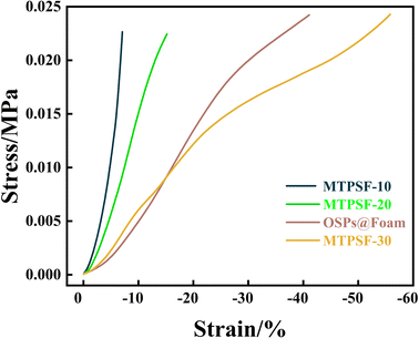 |
| | Fig. 12 The stress–strain curves of all samples. | |
 |
| | Fig. 13 The compression experiment of OSPs@Foam (a) and MTPSF-30 (b). | |
4. Conclusions
In this study, porous superhydrophobic foam (MTPSF) was fabricated by applying the multi-template high-internal-phase emulsion method. The material with a high water contact angle of 143°, a water sliding angle of 6°, an oil contact angle of about 0°, and a porosity of 97.39% is a superhydrophobic–superoleophilic three-dimensional porous material. The OSPs and EAC added to the emulsion system could construct smaller-diameter pores, and the former also stabilised the emulsion precursors. MPTF-30 demonstrated excellent oil absorption capacity, with a saturation absorption multiplicity ranging from 39.40 g g−1 to 102.32 g g−1 for the tested oils. The sorption process of material aligned well with the pseudo-second kinetics model and the Webber–Morris model. Furthermore, material exhibited remarkable reusability and toughness. It could undergo 10 absorption–desorption cycles without significant damage and endure up to 55% ultimate compression. In conclusion, MTPSF is an ideal material for future oil–water separation applications due to its outstanding performance.
Author contributions
Zhipeng Wen: investigation, data analysis, writing – original draft, writing – review and editing. Huilin Yang: investigation and data analysis. Mingzhe Lv: partial funding support. Chuanming Yu: experimental protocol formulation. Yong Li: major financial support.
Conflicts of interest
There are no conflicts to declare.
Acknowledgements
This paper was sponsored by the Scientific Research Start-up Funds of Guangdong Ocean University (R18018), Guangdong Postgraduate Joint Training Base, Postgraduate Education Innovation Project of Guangdong Ocean University (202329), and the Science and Technology Program of Zhanjiang City (2022A01064).
References
- Y. Wang, K. Lee, D. Liu, J. Guo, Q. Han, X. Liu and J. Zhang, Environ. Pollut., 2020, 263, 114343 CrossRef CAS PubMed.
- J. H. Cohen, L. R. McCormick and S. M. Burkhardt, Bull. Environ. Contam. Toxicol., 2014, 92, 381–387 CrossRef CAS PubMed.
- R. Almeda, C. Hyatt and E. J. Buskey, Ecotoxicol. Environ. Saf., 2014, 106, 76–85 CrossRef CAS PubMed.
- Z. Jiang, Y. Huang, X. Xu, Y. Liao, L. Shou, J. Liu, Q. Chen and J. Zeng, Acta Ecol. Sin., 2010, 30, 8–15 CrossRef.
- H. Singh, N. Bhardwaj, S. K. Arya and M. Khatri, Environ. Nanotechnol., Monit. Manage., 2020, 14, 100305 Search PubMed.
- R. de la Huz, M. Lastra, J. Junoy, C. Castellanos and J. M. Viéitez, Estuarine, Coastal Shelf Sci., 2005, 65, 19–29 CrossRef CAS.
- J. P. Incardona, T. K. Collier and N. L. Scholz, Toxicol. Appl. Pharmacol., 2004, 196, 191–205 CrossRef CAS PubMed.
- C. E. Hicken, T. L. Linbo, D. H. Baldwin, M. L. Willis, M. S. Myers, L. Holland, M. Larsen, M. S. Stekoll, S. D. Rice, T. K. Collier, N. L. Scholz and J. P. Incardona, Proc. Natl. Acad. Sci. U.S.A., 2011, 108, 7086–7090 CrossRef CAS PubMed.
- G. Troisi, S. Barton and S. Bexton, Int. J. Hydrogen Energy, 2016, 41, 16549–16555 CrossRef CAS.
- L. H. Schwacke, C. R. Smith, F. I. Townsend, R. S. Wells, L. B. Hart, B. C. Balmer, T. K. Collier, S. De Guise, M. M. Fry, L. J. Guillette, S. V. Lamb, S. M. Lane, W. E. McFee, N. J. Place, M. C. Tumlin, G. M. Ylitalo, E. S. Zolman and T. K. Rowles, Environ. Sci. Technol., 2014, 48, 93–103 CrossRef CAS PubMed.
- N. F. Putman, F. A. Abreu-Grobois, I. Iturbe-Darkistade, E. M. Putman, P. M. Richards and P. Verley, Biol. Lett., 2015, 11, 20150596 CrossRef PubMed.
- A. C. S. V. de Negreiros, I. D. Lins, C. B. S. Maior and M. J. d. C. Moura, J. Loss Prev. Process Ind., 2022, 80, 104912 CrossRef.
- A. T. Hoang, V. V. Pham and D. N. Nguyen, Int. J. Appl. Eng. Res., 2018, 13, 4915–4928 Search PubMed.
- J. Ge, H.-Y. Zhao, H.-W. Zhu, J. Huang, L.-A. Shi and S.-H. Yu, Adv. Mater., 2016, 28, 10459–10490 CrossRef CAS PubMed.
- A. Hethnawi, O. Kashif, R. Jeong, F. Sagala, K. Hashlamoun, A. D. Manasrah and N. N. Nassar, Colloids Surf., A, 2023, 664, 131191 CrossRef CAS.
- Q. Guo, J. Environ. Chem. Eng., 2022, 10, 108312 CrossRef CAS.
- Y. Ouyang, L. Song, X. Zhao, Z. Li, S. Liu and Z. Yan, Sep. Purif. Technol., 2023, 306, 122600 CrossRef CAS.
- C. Yu, X. Zhuang, S. Zeng, Q. Dong, Z. Jing, P. Hong and Y. Li, RSC Adv., 2019, 9, 17543–17550 RSC.
- K. M. Althubeiti and T. S. Horozov, React. Funct. Polym., 2019, 142, 207–212 CrossRef CAS.
- J. Wang, J. Yang, H. Zhu, B.-G. Li and S. Zhu, Chem. Eng. J., 2023, 456, 141026 CrossRef CAS.
- Y. Zhao, A. Wang, L. Shen, L. Xiao and L. Hou, Microporous Mesoporous Mater., 2022, 341, 112039 CrossRef CAS.
- I. W. Almanassra, L. Jaber, A. Chatla, A. Abushawish, A. Shanableh and M. Ali Atieh, Chem. Eng. J., 2023, 144616 CrossRef CAS.
- A. Menner and A. Bismarck, Macromol. Symp., 2006, 242, 19–24 CrossRef CAS.
- N. R. Cameron, D. C. Sherrington, L. Albiston and D. P. Gregory, Colloid Polym. Sci., 1996, 274, 592–595 CrossRef CAS.
- A. Carranza, M. G. Pérez-García, K. Song, G. M. Jeha, Z. Diao, R. Jin, N. Bogdanchikova, A. F. Soltero, M. Terrones, Q. Wu, J. A. Pojman and J. D. Mota-Morales, ACS Appl. Mater. Interfaces, 2016, 8, 31295–31303 CrossRef CAS PubMed.
- N. R. Cameron and D. C. Sherrington, in Biopolymers Liquid Crystalline Polymers Phase Emulsion, Springer Berlin Heidelberg Berlin, Heidelberg, 1996, vol. 126, pp. 163–214 Search PubMed.
- C. Yu, W. Lin, J. Jiang, Z. Jing, P. Hong and Y. Li, RSC Adv., 2019, 9, 37759–37767 RSC.
- Y. Zhu, H. Li, W. Huang, X. Lai and X. Zeng, Surf. Interfaces, 2023, 37, 102746 CrossRef CAS.
- M. Satria and T. A. Saleh, J. Environ. Chem. Eng., 2022, 10, 108577 CrossRef CAS.
- H. Bi, X. Xie, K. Yin, Y. Zhou, S. Wan, L. He, F. Xu, F. Banhart, L. Sun and R. S. Ruoff, Adv. Funct. Mater., 2012, 22, 4421–4425 CrossRef CAS.
- X. Yang, N. Yang, Z. Gong, F. Peng, B. Jiang, Y. Sun and L. Zhang, Chin. J. Chem. Eng., 2023, 54, 296–305 CrossRef.
- H. Wang, J. Wang, M. Cui, R. Su and R. Huang, Sep. Purif. Technol., 2023, 316, 123826 CrossRef CAS.
- M. Gharehasanloo, M. Anbia and F. Yazdi, Int. J. Biol. Macromol., 2023, 240, 124159 CrossRef CAS PubMed.
- Y. Wang, H. Lu, X. Wang, L. Han, X. Liu, D. Cheng, F. Yang, F. Guo and W. Wang, Sep. Purif. Technol., 2023, 311, 123278 CrossRef CAS.
- C. Bai, H. Hu and C. Ni, Surf. Interfaces, 2023, 37, 102679 CrossRef CAS.
- S. Svilović, D. Rušić and A. Bašić, Desalination, 2010, 259, 71–75 CrossRef.
|
| This journal is © The Royal Society of Chemistry 2023 |
Click here to see how this site uses Cookies. View our privacy policy here.  Open Access Article
 a,
Huilin Yanga,
Mingzhe Lvb,
Chuanming Yu
 *a and
Yong Li*a


